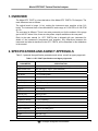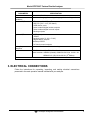
1
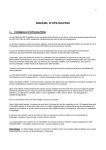
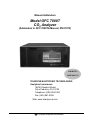
Manual Addendum Model GFC 7000T CO2 Analyzer (Addendum to GFC 7000TA Manual, PN 07272) P/N M07273 DATE 06/11/13 TELEDYNE ELECTRONIC TECHNOLOGIES Analytical Instruments 16830 Chestnut Street City of Industry, CA 91748 Telephone: (626) 934-1500 Fax: (626) 961-2538 Web: www.teledyne-ai.com Teledyne Analytical Instruments Model GFC7000T Carbon Dioxide Analyzer Copyright © 2013 Teledyne Analytical Instruments All Rights Reserved. No part of this manual may be reproduced, transmitted, transcribed, stored in a retrieval system, or translated into any other language or computer language in whole or in part, in any form or by any means, whether it be electronic, mechanical, magnetic, optical, manual, or otherwise, without the prior written consent of Teledyne Analytical Instruments, 16830 Chestnut Street, City of Industry, CA 91748. Warranty This equipment is sold subject to the mutual agreement that it is warranted by us free from defects of material and of construction, and that our liability shall be limited to replacing or repairing at our factory (without charge, except for transportation), or at customer plant at our option, any material or construction in which defects become apparent within one year from the date of shipment, except in cases where quotations or acknowledgements provide for a shorter period. Components manufactured by others bear the warranty of their manufacturer. This warranty does not cover defects caused by wear, accident, misuse, neglect or repairs other than those performed by Teledyne or an authorized service center. We assume no liability for direct or indirect damages of any kind and the purchaser by the acceptance of the equipment will assume all liability for any damage which may result from its use or misuse. We reserve the right to employ any suitable material in the manufacture of our apparatus, and to make any alterations in the dimensions, shape or weight of any parts, in so far as such alterations do not adversely affect our warranty. Important Notice This instrument provides measurement readings to its user, and serves as a tool by which valuable data can be gathered. The information provided by the instrument may assist the user in eliminating potential hazards caused by his process; however, it is essential that all personnel involved in the use of the instrument or its interface be properly trained in the process being measured, as well as all instrumentation related to it. The safety of personnel is ultimately the responsibility of those who control process conditions. While this instrument may be able to provide early warning of imminent danger, it has no control over process conditions, and it can be misused. In particular, any alarm or control systems installed must be tested and understood, both as to how they operate and as to how they can be defeated. Any safeguards required such as locks, labels, or redundancy, must be provided by the user or specifically requested of Teledyne at the time the order is placed. Therefore, the purchaser must be aware of the hazardous process conditions. The purchaser is responsible for the training of personnel, for providing hazard warning methods and instrumentation per the appropriate standards, and for ensuring that hazard warning devices and instrumentation are maintained and operated properly. Teledyne Analytical Instruments, the manufacturer of this instrument, cannot accept responsibility for conditions beyond its knowledge and control. No statement expressed or implied by this document or any information disseminated by the manufacturer or its agents, is to be construed as a warranty of adequate safety control under the user’s process conditions. Trademarks All trademarks, registered trademarks, brand names or product names appearing in this document are the property of their respective owners and are used herein for identification purposes only. Teledyne Analytical Instruments ii Model GFC7000T Carbon Dioxide Analyzer ABOUT THIS ADDENDUM This addendum, part number 07273, is to be used in conjunction with the Model GFC 7000TA operation manual, part number 07272. Where operation of the Model GFC 7000T diverges from that of the Model GFC 7000TA, this addendum takes precedence. Please note that the GFC 7000TA operation manual contains important SAFETY messages for this instrument. It is strongly recommended that you read that operation manual in its entirety as well as this addendum, before operating the instrument. Teledyne Analytical Instruments iii Model GFC7000T Carbon Dioxide Analyzer This page intentionally left blank Teledyne Analytical Instruments iv Model GFC7000T Carbon Dioxide Analyzer TABLE OF CONTENTS About This Addendum ...............................................................................................................iii Table of Contents ...................................................................................................................... v 1. Overview ............................................................................................................................ 1 2. Specifications and Agency Approvals ................................................................................ 1 3. Electrical Connections ........................................................................................................ 2 4. Pneumatic Connections ..................................................................................................... 3 4.1. Basic and Zero/Span Valve Option Configurations ........................................................ 3 4.2. Making the Pneumatic Connections ............................................................................... 5 5. Relay alarm outputs (Standard configuration) .................................................................... 6 6. Relay alarm outputs (Air Products Configuration) .............................................................. 7 7. Control inputs (Air Products Configuration only) ................................................................ 7 Teledyne Analytical Instruments v Model GFC7000T Carbon Dioxide Analyzer This page intentionally left blank. Teledyne Analytical Instruments vi Model GFC7000T Carbon Dioxide Analyzer 1. OVERVIEW The Model GFC 7000T is a close derivative of the Model GFC 7000TA CO2 Analyzer. The main differences are as follows. The optical bench is longer (14 m), making the instrument more sensitive at low CO2 levels. The instrument has a user-selectable full scale range of 0-100 PPB to 0-100 PPM of CO2. The rear panel is different. There is an extra pneumatic port for the exhaust of the purge gas to the GFC wheel. Also, there are relay alarm outputs available on the rear panel. Refer to the main manual (i.e. GFC 7000TA) that is shipped with your instrument for details of the instrument’s components and operation. Any differences between this instrument and what is described in the GFC 7000TA, will be described in this Addendum to the manual. 2. SPECIFICATIONS AND AGENCY APPROVALS Table 2-1 presents the specification parameters and values, as well as agency approvals. Table 2-1. GFC 7000T Specifications and Agency Approvals PARAMETER Ranges SPECIFICATION User selectable to any full scale range from 0-2 ppm to 0-2,000 ppm Measurement Units ppb, ppm, µg/m3, mg/m3 (user selectable) Zero Noise < 0.1 ppm RMS Span Noise < 1% of reading RMS Lower Detectable Limit < 0.2 ppm Zero Drift (24 hours) < 0.25 ppm Span Drift (24 hours) < 0.5% of reading Linearity 1% of full scale Precision 0.5% reading Lag Time 10 sec Rise/Fall Time <60 sec to 95% Sample Flow Rate 800 cm3/min. ± 10% Temperature Range 5 - 40C operating Humidity Range 0-95% RH, Non-Condensing Temp Coefficient < 0.05 % of reading per C Voltage Coefficient < 0.05 % of reading per V Dimensions (HxWxD) 7" x 17" x 23.5" (178 mm x 432 mm x 597 mm) Weight 40 lb (18.1 kg) AC Power 100 – 120V 50/60 Hz, Teledyne Analytical Instruments 1 Model GFC7000T Carbon Dioxide Analyzer PARAMETER SPECIFICATION 220 – 240 V 50/60 Hz Environmental Conditions Installation Category (Over voltage Category) II Pollution Degree 2 Standard I/O 1 2 2 8 6 4 Optional I/O 1 USB com port 1 RS485 8 analog inputs (0-10V, 12-bit) 4 digital alarm outputs Multidrop RS232 3 4-20mA current outputs Analog Output Resolution 1 part in 4096 of selected full-scale voltage Certifications CE: IEC 61010-1:2001, EN61326 - Class A North American: cNEMKO (Canada): CAN/CSA-C22.2 No. 61010-1-04 NEMKO-CCL (US):UL No.61010-1 (2nd Edition) Ethernet: 10/100Base-T RS-232 (300 – 115,200 baud) USB device ports opto-isolated digital status outputs opto-isolated digital control inputs analog outputs 3. ELECTRICAL CONNECTIONS Follow the instructions for unpacking, inspecting, and making electrical connections presented in the main operation manual included with your analyzer. Teledyne Analytical Instruments 2 Model GFC7000T Carbon Dioxide Analyzer 4. PNEUMATIC CONNECTIONS This section provides information on the basic pneumatic configuration and the zero/span valve option pneumatic configuration. First are diagrams to illustrate the configurations, followed by a description of the pneumatic ports, and then step-by-step instructions for attaching the lines. 4.1. BASIC AND ZERO/SPAN VALVE OPTION CONFIGURATIONS CAUTION Sample and calibration gases should only come into contact with PTFE (Teflon), FEP, glass, stainless steel or brass. NOTE To prevent dust from entering the gas flow channels, your analyzer was shipped with small plugs inserted into each of the pneumatic fittings on the back panel. Remove these dust plugs and store for future use before proceeding. Figure 4-1 illustrates the most common configuration for gas supply and exhaust lines to the Model GFC 7000T Analyzer without an internal pump. Figure 4-2 illustrates the pneumatic connections for optional configuration with optional zero/span valves. Table 4-1 describes the pneumatic ports. Note that the flowmeter could also be configured upstream of the instrument. Since most flowmeters are calibrated at ambient pressure, ensure that the flow going through the flow meter is at ambient pressure, when it is placed upstream. Teledyne Analytical Instruments 3 Model GFC7000T Carbon Dioxide Analyzer Figure 4-1. Pneumatic Connections for Pressurized Sample Delivery (w/o Internal Pump) Figure 4-2. Pneumatic Connections–Configuration with Zero/Span Valve Option Teledyne Analytical Instruments 4 Model GFC7000T Carbon Dioxide Analyzer Table 4-1. Model GFC 7000T Pneumatic Connections Rear Panel Label Function SAMPLE Connect a gas line from the source of sample gas here. Calibration gasses are also inlet here on units without zero/span valve option installed. EXHAUST Connect an exhaust gas line of not more than 10 meters long here. PRESSURE SPAN On units with zero/span valve option installed, connect a gas line to the source of calibrated span gas here. VENT SPAN Not used ZERO On units with zero/span valve option installed, attach a gas line to the source of zero air here. TO PURGE This inlet supplies purge air to the GFC wheel housing Connect a source of dried air that has been scrubbed of CO2. FROM PURGE This exhausts purge air to the GFC wheel housing. Connect an exhaust gas line of not more than 10 meters long here. It is only used on the GFC 7000TU instrument. 4.2. MAKING THE PNEUMATIC CONNECTIONS CAUTION Venting should be outside the shelter or immediate area surrounding the instrument. 1. Attach a sample inlet line to the sample inlet port. The SAMPLE input line should not be more than 2 meters long. 2. Attach sources of zero air and span gas 3. Span Gas is a gas specifically mixed to match the chemical composition of the type of gas being measured at near full scale of the desired measurement range. When CO2 measurements are to be made with the Teledyne Instruments Model GFC 7000T Analyzer it is recommended that you use a gas calibrated to have a CO2 content equaling 80% of the range of compositions being measured. Teledyne Analytical Instruments 5 Model GFC7000T Carbon Dioxide Analyzer EXAMPLE: If the application is to measure between 0 ppm and 50 ppm, an appropriate Span Gas would be 40 ppm. If the application is to measure between 0 ppm and 100 ppm, an appropriate Span Gas would be 80 ppm. Zero Air is similar in chemical composition to the earths atmosphere but scrubbed of all components that might affect the analyzer’s readings. In the case of CO2 measurements this means CO2 less than 0.1 ppm of CO2 and Water Vapor. Zero Air can be purchased in pressurized canisters or created using a Teledyne Instruments Model 701 Zero Air Generator in combination with a canister of indicating soda-lime. 4. Attach an exhaust line to the exhaust outlet port. The exhaust from the analyzer and vent lines should be vented to atmospheric pressure using maximum of 10 meters of 1/4” PTFE tubing. 5. Attach a source of dried air scrubbed of CO2 to the purge inlet port The source of purge gas should be at least 10 psig and capable of maintaining a flow of at least 1 liter/min. Purge source gas pressure should not exceed 30 psig. The purge exhaust is only used on the GFC 7000TU model. 6. Once the appropriate pneumatic connections have been made, check all pneumatic fittings for leaks. 5. RELAY ALARM OUTPUTS (STANDARD CONFIGURATION) There are 4 relay alarm outputs (AL1-AL4) on the rear panel. AL1 is for system okay, AL2 is for concentration limit 1 exceeded and AL3 is for concentration limit 2 exceeded. AL4 is not used The relay alarm output AL1 is enabled all the time, whereas the AL2 and AL3 can be enabled/disabled by going into the diagnostics menu (with 929 password), then factory options, then turning conc. Alarm Relays ON or OFF. When the concentration alarm relays are enabled, concentration alarms status is no longer available through the “Status output” pins. So, either the alarm relays or the status bits could be used to monitor the concentration alarms but not both at the same time. The default factory setting is to enable the concentration alarm relays. The AL1 relay is energized when the system is okay and de-energized when the system has a fault. The AL2 and AL3 relays energize when the corresponding concentration limits are exceeded. Teledyne Analytical Instruments 6 Model GFC7000T Carbon Dioxide Analyzer 6. RELAY ALARM OUTPUTS (AIR PRODUCTS CONFIGURATION) There are 4 relay alarm outputs (AL1-AL4) on the rear panel. AL1 is for “system okay”, AL2 is for “high range status” and AL3 is for “zero calibration status” AL4 is not used The AL1 relay is energized when the system is okay and de-energized when the system has a fault. The AL2 relay is energized when the high auto-range is in use and and AL3 relays energize when the the instrument is in zero calibration mode. 7. CONTROL INPUTS (AIR PRODUCTS CONFIGURATION ONLY) An additional control input is available on this instrument. Control input “C” is used to select the range for remote calibration. When input C is low, the instrument selects high range during contact closure calibration. Teledyne Analytical Instruments 7