1
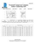
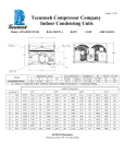
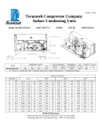
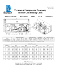
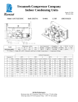
April 16, 2013 Tecumseh Compressor Company Indoor Condensing Units Model: AWA9514ZXNXE BoM: 2B3273-1 R-404A 1.5 HP AIRCOOLED Dimensions, inches Line Connection* Pumpdown Air L W H CH Suction Liquid SCFM 90 F 90% 36.0 23.5 15 14.25 7/8” S 3/8” S 10.53 lbs 1200 AWA9514ZXNXE * F = Flare, S = Solder, RF or RS = Rotolock with Flare or Solder Connections, C = Compression Fitting Model Oil Ch Oz. 38.5 Gr. Wt. Lbs. --- Ambient Temperatures Evaporator T °F PSIG 80F BTUH Watts 90F Cond T BTUH Watts 100F Cond T BTUH Watts 110F Cond T BTUH Watts Cond T -10 23.2 7273 1385 91 6028 1379 101 4765 1337 111 3695 1248 122 -5 28.1 8487 1494 92 7130 1493 102 5811 1458 112 4575 1384 122 0 32.8 9783 1603 94 8323 1610 104 6928 1582 113 5534 1523 123 5 37.9 11162 1713 96 9606 1728 105 8116 1709 114 6571 1663 124 10 43.3 12624 1823 98 10978 1847 107 9375 1837 116 7688 1806 125 15 49.1 14168 1933 100 12441 1968 109 10705 1969 117 8883 1951 127 20 55.5 15795 2044 102 13994 2091 111 12107 2103 119 10157 2097 129 25 62.2 17505 2155 104 15637 2216 113 13579 2239 122 11509 2247 131 30 69.5 19297 2266 107 17371 2343 116 15123 2378 124 12941 2398 133 35 77.2 21171 2377 109 19194 2471 118 16738 2519 127 14451 2551 135 40 85.5 23128 2489 112 21108 2600 121 18425 2663 129 16040 2707 138 45 94.3 25168 2601 114 23111 2732 123 20182 2809 132 17708 2864 140 60 Hz Performance Return gas temp. 40F Evaporator Temp. 20F or less, 5F sub-cooling Return gas temp. 65F for Evaporator Temp. > 20F, 5F sub-cooling April 16, 2013 Specifications/ Parts: Model Unit Bill of Material Nominal Volts-Hz-Ph Refrigeration Range Design Pressure Low Design Pressure High Voltage Range Min. Circuit Ampacity Max. Fuse Size (amps) Compressor Model Comp. Bill of Material Compressor RLA/LRA Overload Relay Run Capacitor Run Capacitor Rating Start Capacitor Start Capacitor Rating Contactor Unit Drawing Wiring Diagram AWA9514ZXNXE 2B3273-1 208-230-60-1 -10° to 45°F 181 450 180 to 254 17.1 25 AWA9512ZXN AW611FT-163-P4 12.4 / 60 INTERNAL 820ARR3J50 85PR370F17 35MFD 370V(M) VDE 85PS330C24 88-108 MFD 330V VDE N/A DGU1918-73 91267-01 Fan Motor Fan Motor RLA Fan Blade Fan Guard Fan Shroud Dual Pressure Control Condenser Receiver Tank with Valve Liquid Filter Sight Glass Suction Valve Rotolock Valve Gasket Discharge Valve Suction Filter * Accumulator * Crankcase Heater Defrost Timer * * = Equipped Units Only Electrical Diagram 810-10012 (2) 0.8 Each 515-10005 (2) 570-10001 (2) 707-10001 14955206 506-10007 510-10004 70081 70084 31529-1 30233 56630-A N/A N/A N/A N/A