1
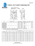
Tecumseh Compressor Company Indoor Condensing Units August 18, 2014 Revision: REL Model: AJA7512ZXDXC BoM: 2B3276-1 R-404A 1.5 HP AIRCOOLED Dimensions, inches Line Connection* Pumpdown Air L W H CH Suction Liquid 90 F 90% SCFM 36.0 23.5 15.1 12.1 5/8” S 3/8” S 10.53 lbs 1200 AJA7512ZXDXC * F = Flare, S = Solder, RF or RS = Rotolock with Flare or Solder Connections, C = Compression Fitting Model Oil Ch Oz. 26.44 Gr. Wt. Lbs. --- Ambient Temperatures Evaporator T 80F 90F 100F 110F °F PSIG BTUH Watts Cond T BTUH Watts Cond T BTUH Watts Cond T BTUH Watts Cond T -10 23.2 6560 1331 91 6066 1327 100 5222 1324 109 4429 1320 118 -5 28.1 7915 1419 92 6956 1428 101 6047 1437 110 5187 1445 119 0 32.8 8920 1507 94 7892 1527 103 6913 1548 112 5982 1569 121 5 37.9 9967 1592 95 8867 1626 104 7813 1659 113 6806 1692 122 10 43.3 11049 1677 97 9872 1722 105 8740 1768 115 7652 1813 123 15 49.1 12158 1760 98 10900 1818 107 9686 1876 116 8513 1933 125 20 55.5 13283 109 10640 1982 118 9378 2052 126 --- 110 --- 11594 --- 2088 --- 119 --- 128 --- 2005 --- 2170 69.5 12985 --- 10239 30 ----- 100 --- 1912 62.2 1842 --- 11941 25 11084 2286 129 60 Hz Performance Return gas temp. 40F Evaporator Temp. 20F or less, 5F sub-cooling Return gas temp. 65F for Evaporator Temp. > 20F, 5F sub-cooling August 18, 2014 Revision: REL Specifications/ Parts: Model Unit Bill of Material Nominal Volts-Hz-Ph Refrigeration Range Design Pressure Low Design Pressure High Voltage Range Min. Circuit Ampacity Max. Fuse Size (amps) Compressor Model Comp. Bill of Material Compressor RLA/LRA Overload Relay Run Capacitor Run Capacitor Rating Start Capacitor Start Capacitor Rating Contactor Unit Drawing Wiring Diagram AJA7512ZXDXC 2B3276-1 208-230-60-1 -10° to 30°F 181 450 180 to 254 13.1 20 AJA7494ZXD AJ202ET-188-P21 8.9 / 54 INTERNAL 8200RVAM25 85PR370F20 25MFD 370V(M) VDE 85PS250B87 216-259 MFD 250V VDE N/A DGU1893-92 91267-01 Fan Motor Fan Motor RLA Fan Blade Fan Guard Fan Shroud Dual Pressure Control Condenser Receiver Tank with Valve Liquid Filter Sight Glass Suction Valve Rotolock Valve Gasket Discharge Valve Suction Filter * Accumulator * Crankcase Heater Defrost Timer * * = Equipped Units Only Electrical Diagram 810-10012 (2) 0.8 Each 515-10005 (2) 570-10001 (2) 707-10001 14955206 506-10007 510-10004 70081 70084 31529-1 30233 56630-A N/A N/A N/A N/A