1
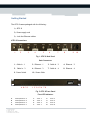
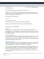
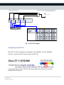
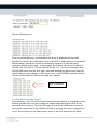
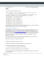
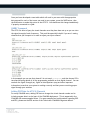
Technicolor ATSC-8
User’s Guide
© 2012 Technicolor. All Rights reserved
Introduction
This document describes the process and procedures for integrating the ATSC-8 product with
the COM1000 digital head-end system. The ATSC-8, available from Technicolor, will allow
for the reception of over-the-air broadcasts of digital broadcasts and output of this content
over an Internet Protocol (IP) output. Used in combination with a COM1000 system
containing a QAM6 EdgeQAM, this IP output can be modulated over a digital QAM network in
combination with DIRECTV premium programming if COM24 or COM24-FLX receivers are used.
Over-the-Air Broadcasts
ATSC replaced NTSC broadcasts in the US in 2009 and is the primary transmission for local
digital broadcasts of major network stations. ATSC signals use the same 6MHz bandwidth as
analog NTSC television channels, but are able to provide many programs within this digital
broadcast contained on sub-channels. For instance, many broadcasters will have a main
channel located in the .1 sub-channel, and provide other secondary channels on .2 and .3
sub-channels. Terrestrial broadcasters use an 8VSB modulation to carry 19.39Mbit/s,
typically containing MPEG2 encoded content.
Why Use ATSC broadcasts?
1) In-the-Clear. ATSC broadcasts don’t require any content protection to be added
when they are re-broadcast in a local cable environment. This allows providers to
deliver HD programming “in-the-clear” to TVs. Combined with the COM24-FLX card
providing DIRECTV SD programming, also “in-the-clear”, an entire channel ring could
be set up with mixed HD and SD programming.
2) Free. ATSC broadcasts are available for free in nearly every US city and only require
a simple UHF antenna to receive. To see if ATSC broadcasts are available in your
area, you can visit http://dtv.gov/stationlist.htm and search on your zip code.
3) Sub-channels. Most major local networks broadcast a second or third local channel
which contains important weather related content, local sports, and secondary
programming of value to that local market. These secondary channels are not
typically available on satellite or cable broadcasts.
Technicolor MCS
101 W. 103rd St
Indianapolis, IN 46290
www.technicolor.com/mcs
Getting Started
The ATSC-8 comes packaged with the following:
1) ATSC-8
2) Power supply cord
3) 4 x 6-foot Ethernet cables
ATSC-8 Connections:
1
2
3
4
5
6
7
8
9
Fig. 1 ATSC-8 Back Panel
Back Connectors
1. Cable In – 1
2. Ethernet – 1
3. Cable In – 2
4. Ethernet – 2
5. Cable In – 3
6. Ethernet – 3
7. Cable In – 4
8. Ethernet – 4
9. Power Switch
10. Power Cable
A B C D
1 2 3 4 5 6 7 8
Fig. 2 ATSC-8 Front Panel
Front LED Indicators
A
B
C
D
Power/Network – 4
Power/Network – 3
Power/Network – 2
Power/Network – 1
Technicolor MCS
101 W. 103rd St
Indianapolis, IN 46290
www.technicolor.com/mcs
1.
3.
5.
7.
Tuner
Tuner
Tuner
Tuner
1
3
5
7
2.
4.
6.
8.
Tuner
Tuner
Tuner
Tuner
2
4
6
8
10
Power/Network LED:
Green: The ATSC-8 is powered on and connected to the network.
Flashing Green: The ATSC-8 is powered on and working to obtain an IP address from the
network. If the PC is connected directly to the ATSC-8, then the light will continue to blink
until the PC makes contact with the ATSC-8.
Red: Powered on, No Network Link.
Tuner LED:
Off: The tuner is not in use.
Green: The tuner is in use, tuned to a channel, and streaming data.
Flashing: The tuner is reserved for use, but is not actively streaming data.
Connection to the COM1000
Mounting:
The ATSC-8 is rack mountable and can be easily mounted in the same location as the
COM1000 system. It is recommended that at least 1RU of space be left between the ATSC-8,
the COM1000, and any other components so that each component will receive good air-flow
in the mounting location.
Connecting an antenna:
The ATSC-8 has 4 RF connectors for inputting antenna signals to the 4 dual tuners. Connect
the antenna input into a 2 GHz 4-way splitter with the outputs of the splitter going to each
of the RF connectors on the ATSC-8. In some locations an amplifier may be required between
the antenna and splitter for best reception.
Connecting the network:
The ATSC-8 has 4 Ethernet connectors for outputting the IP video streams. Connect each of
the 4 Ethernet connectors to an external 5-port Gigabit Switch. Connect the 5th port from
the 5-port gigabit switch to slot-1 GbE-1 card inserted in the COM1000.
NOTE: ATSC channels typically have much higher bitrates than DIRECTV HD channels with
data rates around 14-18 Mbits/s. In order to send 8 channels to the QAM6, the GbE-1 card
must be used to insure that the data is received. If only a couple of ATSC channels are
desired, then the 100Mb management port located on the QAM6 could be used to receive
these data streams.
Technicolor MCS
101 W. 103rd St
Indianapolis, IN 46290
www.technicolor.com/mcs
Off Air Antenna
4-way Splitter
IP OUT
RF IN
IP OUT
RF IN
IP OUT
RF IN
IP OUT
ATSC-8
RF IN
Gigabit Ethernet Switch
GbE1
Fig. 3 Connection Diagram
Configuring the ATSC-8
The ATSC-8 is fully controlled and commanded by the COM1000. From the COM1000
interface, to access the ATSC control, select the ATSC tab.
If your system does not show the ATSC tab, please update your software to the latest
available from Technicolor.
Technicolor MCS
101 W. 103rd St
Indianapolis, IN 46290
www.technicolor.com/mcs
Discover the IP Addresses of the ATSC Tuner Modules
When the ATSC-8 is shipped from Technicolor, it will be in DHCP mode and expect to get
assigned an IP address from a router. Since our connection diagrams and common
installation practices do not include a router or DHCP server, the IP addresses may not be
assigned. The ATSC-8 will also generate an Auto-IP address such that a PC connected
directly to the unit without a router can communicate to the device.
Each ATSC-8 has 4 tuning modules containing 2 tuners each. Each Tuning module can have
two unique IP addresses, so in total, the ATSC-8 will have 8 unique IP addresses (two for
each tuning module). When first connecting to the ATSC-8 or to see what the IP addresses of
the tuners are, you can press the DISCOVER button on the bottom of the ATSC page. The
following is a result from a Discover inquiry. One address for each module is the Auto-IP
address assigned by the module itself, the other can be Auto-IP, static or assigned by DHCP.
This shows that 8 total IP addresses were found, and since each of the 4 tuner modules has 2
possible IP addresses, the 2 addresses are displayed.
Changing the IP Addresses of the Tuners
You may change the IP addresses of the tuners to a range within the same IP configuration of
the COM1000 by using the SET button on the ATSC page. You must first type in the base
number for the assignment, then hit the SET button. For instance, if you’d like the IP
addresses to be in a range starting at 192.168.3.50, then use 192.168.3.50 as the base
address.
Technicolor MCS
101 W. 103rd St
Indianapolis, IN 46290
www.technicolor.com/mcs
With the following result:
From our previous discovery, we showed both the known IP addresses and the AutoIP
addresses for each of the 4 addressable tuners in the ATSC-8. When making the requested IP
address change, each device receives 2 commands to change the IP with the second
command resulting in the change. In this example, the 4 tuners will have an IP address of
192.168.3.54, 192.168.3.55, 192.168.3.56 and 192.168.3.57. You can verify by again using
the DISCOVER button from the ATSC page. *Note that although the above screen shows the
Auto-IP addresses being changed, in fact they are not. A new DISCOVER command will show
only the variable addresses that have actually been changed.
New IP Addresses
Loading Data from the Tuners
From the factory, the ATSC-8 tuners will not be tuned to any channels or streaming any data,
however you may have a unit set up which has already been tuned and you’d like to see
what each tuner is playing. From the ATSC page, you can hit the LOAD button to have the
device send a report back to the COM1000 interface to see what the current configuration is
set to. Once you have run the load function, return to the ATSC page to see the results.
Technicolor MCS
101 W. 103rd St
Indianapolis, IN 46290
www.technicolor.com/mcs
In this example, you’ll see which tuner is tuned to each RF frequency, as well as which QAM
IP address and port number each channel has been assigned.
Changing the Tuning Table
The tuning table can easily be changed by creating or editing the command lines for each of
the 8 available tuners. You can verify frequencies and virtual channel numbers in your
specific area by using the http://dtv.gov/stationlist.htm website. Note that some channels
will be on the same frequency as the virtual channel number, but most channel numbers will
have a different frequency listing. For example, channel 8 in Indianapolis, is actually
broadcast on channel 9.
Each listing in the tune table will need all the required fields entered. Below is an entry
along with a description of what each field contains.
192.168.3.54 0 9 8.1 192.168.6.2 35
192.168.3.54 = IP address of the tuner to be set.
0 = Tuner index. There are 2 tuners per IP address, so this is either 0 or 1.
9 = Digital channel number of the broadcasting station.
8.1 = Virtual channel number and program stream desired.
192.168.6.2 = IP Address of the QAM to output the tuned channel.
35 = Port number of the QAM corresponding to the desired QAM channel which will carry the
tuned ATSC channel.
Technicolor MCS
101 W. 103rd St
Indianapolis, IN 46290
www.technicolor.com/mcs
Once you have developed a tune table which will work in your area with the appropriate
data entered for each of the tuners you need in your system, press the SAVE button, then
the RUN button to make this active on the ATSC-8. You should see this change immediately
if properly connected to a QAM.
QUERY Command
The ATSC-8 is able to Query the tuned channels once they have been set up so you can view
the signal strength of each frequency. This could be especially helpful if you aren’t seeing
channels that you’d expect to or need to adjust your input antenna.
In this example you can see that channel 9 is not tuned (lock=none) and that channel 25 is
tuned and showing details of all the programming available on that digital channel. You can
see both the Signal Strength (ss), Signal to Noise Quotient (snq) and other important
information to see that your system is working correctly and that you are receiving proper
signal through your antenna.
Adding PSIP Data for ATSC-8 Channels
For many COM1000 users, adding PSIP data to change the virtual channel number and to
include program data is a vital part of the COM1000 deployment. This is supported in the
COM1000 with some examples below. For more examples and configurations regarding PSIP
and EPG, please see the EPG section of the Technicolor COM1000 Integrators Manual.
Technicolor MCS
101 W. 103rd St
Indianapolis, IN 46290
www.technicolor.com/mcs
From the EPG page, entering the following data from the examples above will give you the
expected results. Since DIRECTV program data typically only exists for “major” channels
broadcast over ATSC, the PSIP program data can only be applied to these channels. You will
see in the below example that the minor channels are given program names such as
WTHR_Local_Weather. No program data can be provided for these minor channels via the
Technicolor PSIP interface.
Channel 6.1 which was being sent to the QAM on port 17 would only be available on the RF
frequency the QAM is configured to. In our example, this happens to be 30.1 (see QAM
configuration in the Integrator’s Manual). We desire to have channel 6.1 be visible on the TV
on channel 6.1, so the above example will create this virtual channel for port 17, as well as
add the program data from DIRECTV channel 6, which in Indianapolis is the same channel.
Channel 6.2 is unable to be associated with program data, however, the virtual channel data
can be set so rather than on channel 30.2, the ATSC program can be tuned at virtual channel
6.2.
By using the 1.2.3.4 in the DestIP field, only PSIP is being generated and there will be no EPG
created. If EPG is desired as well as PSIP, the QAM IP and port number can be inserted in the
DestIP and DestPort fields respectfully.
Technicolor MCS
101 W. 103rd St
Indianapolis, IN 46290
www.technicolor.com/mcs