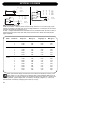
1
P2
LEVEL PILOT
ADMINISTRATOR’S MANUAL
IMPORTANT SAFETY INSTRUCTIONS
The lightning flash with an arrowhead
symbol within an equilateral triangle, is
intended to alert the user to the
presence of uninsulated "dangerous voltage" within the product's enclosure that may be of
sufficient magnitude to constitute a risk of
electric shock to persons.
The exclamation point within an
equilateral triangle is intended to alert
the user to the presence of important
operating and maintenance (servicing)
instructions in the literature accompanying the
product.
1
2
3
4
5
6
7
Warning!
•
To reduce the risk of fire or electrical shock,
do not expose this equipment to dripping or
splashing and ensure that no objects filled
with liquids, such as vases, are placed on the
equipment.
•
This apparatus must be earthed.
•
Use a three wire grounding type line cord
like the one supplied with the product.
•
Be advised that different operating voltages
require the use of different types of line
cord and attachment plugs.
•
Check the voltage in your area and use the
correct type. See table below:
8
9
10
11
12
13
Read these instructions.
Keep these instructions.
Heed all warnings.
Follow all instructions.
Do not use this apparatus near water.
Clean only with dry cloth.
Do not block any ventilation openings. Install
in accordance with the manufacturer's
instructions.
Do not install near any heat sources such
as radiators, heat registers, stoves, or other
apparatus (including amplifiers) that produce
heat.
Do not defeat the safety purpose of the
polarized or grounding-type plug. A
polarized plug has two blades with one
wider than the other. A grounding type plug
has two blades and a third grounding prong.
The wide blade or the third prong are provided
for your safety. If the provided plug does not fit
into your outlet, consult an electrician for
replacement of the obsolete outlet.
Protect the power cord from being walked
on or pinched particularly at plugs,
convenience receptacles, and the point
where they exit from the apparatus.
Only use attachments/accessories specified
by the manufacturer.
Unplug this apparatus during lightning storms
or when unused for long periods of time.
Use only with the cart, stand, tripod,
bracket, or table specified by the
manufacturer, or sold with the apparatus.
When a cart is used, use caution when
moving the cart/apparatus combination to
avoid injury from tip-over.
Refer all servicing to qualified service
personnel. Servicing is required when the
apparatus has been damaged in any way,
such as power-supply cord or plug is
damaged, liquid has been spilled or objects
have fallen into the apparatus, the
apparatus has been exposed to rain or
moisture, does not operate normally, or has
been dropped.
Voltage
Line plug according to standard
110-125V
UL817 and CSA C22.2 no 42.
220-230V CEE 7 page VII, SR section
107-2-D1/IEC 83 page C4.
240V
•
•
•
•
•
BS 1363 of 1984.
Specification for 13A fused
plugs and switched and
unswitched socket outlets.
This equipment should be installed near the
socket outlet and disconnection of the device
should be easily accessible.
To completely disconnect from AC mains,
disconnect the power supply cord from the AC
receptable.
The mains plug of the power supply shall
remain readily operable.
Do not install in a confined space.
Do not open the unit - risk of electric shock
inside.
Caution:
You are cautioned that any change or
modifications not expressly approved in this
manual could void your authority to operate this
equipment.
Service
•
There are no user-serviceable parts inside.
•
All service must be performed by qualified
personnel.
a
IMPORTANT SAFETY INSTRUCTIONS
EMC / EMI.
This equipment has been tested and found to
comply with the limits for a Class B Digital
device, pursuant to part 15 of the FCC rules.
These limits are designed to provide
reasonable protection against harmful
interference in residential installations. This
equipment generates, uses and can radiate
radio frequency energy and, if not installed and
used in accordance with the instructions, may
cause harmful interference to radio
communications. However, there is no
guarantee that interference will not occur in a
particular installation. If this equipment does
cause harmful interference to radio or television
reception, which can be determined by turning
the equipment off and on. The user is
encouraged to try to correct the interference by
one or more of the following measures:
•
•
•
•
Reorient or relocate the receiving antenna.
Increase the separation between the
equipment and receiver.
Connect the equipment into an outlet on a
circuit different from that to which the
receiver is connected.
Consult the dealer or an experienced
radio/TV technician for help.
For the customers in Canada:
This Class B digital apparatus complies with
Canadian ICES-003.
Cet appareil numérique de la classe B est
conforme à la norme NMB-003 du Canada.
b
Certificate Of Conformity
TC Electronic A/S, Sindalsvej 34, 8240
Risskov, Denmark, hereby declares on own
responsibility that following products:
P2 - Level Pilot
- that is covered by this certificate and
marked with CE-label conforms with
following standards:
EN 60065
Safety requirements for mains
(IEC 60065) operated electronic and
related apparatus for household
and similar general use
EN 55103-1 Product family standard for
audio,video, audio-visual and
entertainment lighting control
apparatus for professional
use. Part 1: Emission.
EN 55103-2 Product family standard for
audio, video, audio-visual and
entertainment lighting control
apparatus for professional
use. Part 2: Immunity.
With reference to regulations in following
directives:
73/23/EEC, 89/336/EEC
October 2002
Mads Peter Lübeck
Chief Executive Officer
TABLE OF CONTENTS
INTRODUCTION
ALGORITHM
Important Safety Instructions &
Certificate of conformity . . . . . . . . . .a-b
Table of Contents . . . . . . . . . . . . . . . .3
Introduction . . . . . . . . . . . . . . . . . . . . .4
Quick Start . . . . . . . . . . . . . . . . . . . . .5
Front Panel Overview . . . . . . . . . . . . .6
Rear Panel Overview . . . . . . . . . . . . .8
Signal Flow Diagram . . . . . . . . . . . . . .9
Typical P2 Setups . . . . . . . . . . . . . . .10
Front Panel Operation
- for the Daily User . . . . . . . . . . . . . .11
Installation of the TC Icon PC Editor .13
BASIC OPERATION
Main Page . . .
Loudness Page
EQ Page . . . . .
5-Band Page . .
Limiter . . . . . .
.
.
.
.
.
.
.
.
.
.
.
.
.
.
.
.
.
.
.
.
.
.
.
.
.
.
.
.
.
.
.
.
.
.
.
.
.
.
.
.
.
.
.
.
.
.
.
.
.
.
.
.
.
.
.
.
.
.
.
.
.
.
.
.
.
.
.
.
.
.
.
.
.
.
.
.
.
.
.
.
.24
.26
.28
.31
.32
APPENDIX
Reset menu & Software Load . . . . . .33
Loading Preset Banks . . . . . . . . . . . .34
Notes . . . . . . . . . . . . . . . . . . . . . . . .34
Troubleshooting . . . . . . . . . . . . . . . .34
Technical Specifications . . . . . . . . . .35
Selftest . . . . . . . . . . . . . . . . . . . . . . .36
Presets . . . . . . . . . . . . . . . . . . . . . . .37
The TC Icon PC Editor
Introduction and basic operation of
The TC Icon Editor . . . . . . . . . . . . . .14
Renaming Presets . . . . . . . . . . . . . .15
Preset Structure and handling:
Recall/Store/ Delete . . . . . . . . . . . . .16
Cloning P2’s . . . . . . . . . . . . . . . . . . .18
System I/O Page
Clock Preferences
Analog Levels . . .
Digital Output . . .
GPI . . . . . . . . . . .
.
.
.
.
.
.
.
.
.
.
.
.
.
.
.
.
.
.
.
.
.
.
.
.
.
.
.
.
.
.
.
.
.
.
.
.
.
.
.
.
.
.
.
.
.
.
.
.
.
.
.
.
.
.
.
.
.19
.19
.19
.19
System Front Page/
Front panel Configuration
Wizard Mode . . . . . . . . . . .
Lock Mode . . . . . . . . . . . . .
Lock Activation . . . . . . . . . .
Bypass Mode . . . . . . . . . . .
Lock Code . . . . . . . . . . . . .
Yellow LED Threshold . . . . .
.
.
.
.
.
.
.
.
.
.
.
.
.
.
.
.
.
.
.
.
.
.
.
.
.
.
.
.
.
.
.
.
.
.
.
.
.21
.21
.22
.22
.22
.22
System Net Page
Network Identifier . . . . . . . . . . . . . . .22
ICON Views . . . . . . . . . . . . . . . . . . .22
Engine I/O Page
Input & Clock . . . . . . . . . . . . . . . . . .23
Levels . . . . . . . . . . . . . . . . . . . . . . . .23
TC Electronic, Sindalsvej 34, DK-8240 Risskov – [email protected]
English Version
Prod. No: 606106015
Rev 1.7 – SW – V 1.50
3
INTRODUCTION
Welcome
The P2 is a “set and forget” Loudness pilot and Limiter for Post production and Broadcast. It is
designed especially for fixed installations where a consistent loudness and spectral balance is
required but excels also in peak limiting functions.
Factory loaded with a broad selection of World Standard Presets the P2 can be used right out of the
box. However, via the TC Icon PC Editor, suitable presets can be built by the Administrator and
various lock functions can be applied to ensure no unintended change of settings by the daily User.
Once setup and loaded with presets any person doing video editing, audio production, audio mixing
or tape-copying. Simply pick the predefined optimal preset and avoid having to think about audio
levels again.
Concept
Features
• Audio editing for video
• Audio or tape copying
• Presets can be picked by non
technical personnel with full
confidence in output quality.
• Presets can be created by Audio
Expert via TC Icon Software Editor.
• Easy cloning of multiple P2’s via
standard PCMCIA card.
• Dual mono, Stereo and Wide Stereo
processing
• ALC - Automatic Loudness Control
• Filters and Parameteric EQ
• Live updatable Delay 0-1000 ms
• 5-Band Compression
• Brickwall Limiter
• 24 bit resolution Analog and Digital I/O
• 48 bit internal processing
• Sample Rate Conversion selectable
on/off
• All features mentioned available
simultaneously
About this manual
The latest manual revision can always be downloaded via www.tcelectronic.com
If you have questions unanswered by this manual you may also try looking at our TC Support
Interactive site. This site is also accessed via www.tcelectronic.com
4
QUICK START
Daily User
Requirements
The P2 is correctly connected and loaded with
relevant Front Presets by the Administrator and
powered on.
Lock
The Administrator can decide to activate
different levels of Lock functions. These may
include lock of front panel key operation and/or
lock of the Wizard and Bypass functions.
By the choice of the Administrator the selected
Lock/Unlock function can be
activated/deactivated either by:
- pressing LOCK followed by a four digit code
specified by the Administrator or,
- holding lock for approx 2.5 seconds.
Selecting Presets
Press relevant preset key (1-8) to load preset.
Presets can be loaded only if these keys are
unlocked, (see above).
Presets are “total recall” presets. They set up
all levels, I/O settings and algorithm parameters.
Presets are defined by the experts user to
perfectly match the downstream signal
destination.
Wizard
The Wizard can be activated only if the Wizard
functions are unlocked. (see “Lock” section
above).
Once the Wizard is activated the P2 Level pilot
examines the program material and
automatically suggests optimal compression
settings for highest output. The Wizard can be
set by the Administrator to calculate three
levels of compression; Low, Medium and High.
Administrator
More details on page 18-21 - and setup page
10 for reference.
Requirements
One P2 Level Pilot, a Pentium computer with
Windows 95, 98, NT, 2000, ME or XP installed.
Installation of TC Icon Editor Software
Enter CD, open directory, run Setup and follow
instructions.
Connecting P2
• Connect a PC COM port to the P2 RS232 In.
If possible, notice which computer COM port
you have connected to.
• Programming the P2 does not necessarily
require audio to be connected. However, if
audio connections are needed connect audio
according to Setup illustrations on page 10.
Getting started with the TC Icon Editor
• Power up the P2 and start the TC Icon
software on your computer.
• Go to the Setup/Devices/Port page to select
which COM(1-4) port you you have
connected to. (per default the Editor will look
at COM ports (1-4) automatically.
• Go to the Setup/Devices/Select page. Press
DETECT and assign the detected P2 to one
of the 8 device locations in the right side of
the display. Simply press any of the 8 keys.
• Press the ICON key in the upper left corner
to go the pages from where all local P2
parameters are controlled.
Library Page: handles presets
System Page: handles Clock, Level trims,
Lock functions and the variable yellow LED
Threshold.
Engine: All algorithm parameters.
Cloning P2’s using a PCMCIA card
This is the function used by the Administrator to
clone multiple P2 using a PCMCIA card.
• Load appropriate presets into Front Panel
Bank of the P2 you wish to clone.
• Insert an unprotected PCMCIA card into the
P2 Card slot. (protection key is located on
the edge of the card).
• Go to the System/Card page.
• Decide whether you wish to exclude System
Preset that holds overall Clock settings,
Analog Trim levels, Dither, Status Bit settings
and settings for GPI. To exclude System
Preset activate the “Exclude System Preset”
key.
Then press CREATE CLONE CARD.
• Remove card and go to the target P2 unit.
• Insert the card and power up using the front
panel POWER key while holding the LOCK
key pressed.
• Press the LOCK key again. In this mode the
LOCK key operates as “CONFIRM”.
BYPASS can be used to abort operation.
• The target P2 is now loaded with the
information present on the card.
5
FRONT PANEL OVERVIEW
POWER On/Off
Switches power On/Off.
To completely disconnect from
mains the Rear panel POWER
switch must be used.
PCMCIA slot
For software updates and
preset backups.
ERROR LED
Indicates various error states.
48/44.1/32 kHz LEDs
Indicates current Sample Rate.
ANALOG IN/DIGITAL IN
Indicates currently selected
Input type.
DUAL MONO LED
Indicates that the P2 is
operating in Dual mono mode.
EDITED LED
Indicates that the currently
recalled preset has been
edited but not stored.
This LED will also be lit
when the Wizard has
been activated.
6
GAIN meter
Indicates the max gain applied
on either channels. The
indication is “wideband” type.
OPTIMIZE meters
Indicates the gain optimization
on each of the 5 bands.
LIMIT meter
Indicates the max limitation
performed on either channels.
INPUT/OUTPUT meters
• The Input meters indicate
the level of the Input signal
after the In Gain control.
(set via the TC Icon control
interface).
• The Output meters indicate
the current Output level.
• Threshold value for meter
color change:
For both Input/Output
meters: Below -20dB the
meter LEDs are green.
From -20dB to 0dB LED
color can be green or
yellow.
The value for this color
change is set via the TC
Icon Editor on the System
Front page.
FRONT PANEL OVERVIEW
PRESET keys 1-8
Presets can be recalled from
these keys. Press preset keys
1-8 to instantly recall Front
presets. This type of presets
include settings of all gain and
processing parameters.
Keys can be locked by the
Administrator.
Below each key you can write
preset names. Use the
supplied lithographic crayon or
similar.
WIZARD key
Using the Wizard function the
P2 listens to a section of the
program material; analyzes
and thereafter automatically
adjusts settings using the ALC
to achieve optimal level thus
keeping dynamics intact.
Via the TC Icon Editor three
Wizard compression modes
can be set: Light, Normal or
Heavy. The Wizard mode is
set by the Administrator.
It is NOT possible to change
Wizard mode via the P2
frontpanel.
When the Wizard is activated
the Edited LED will be lit.
To prevent unintended use of
the Wizard the WIZARD key
can also be locked. All lock
functions are set via the TC
Icon PC Editor. When Wizard
is locked it is inoperable from
the front panel controls.
LOCK key
The LOCK key is used to
lock/unlock various functions.
This is set up via the TC Icon
Editor.
Lock Activation
Via the TC Icon Editor two
Lock activation modes can be
selected.
In one mode two separate four
digit codes can be set to
unlock and lock. The code is
set up via the TC Icon PC
Editor.
With the other lock mode
selected lock/unlock can be
performed simply by holding
the LOCK key pressed for 2.5
seconds.
Lock Modes:
Disable:
Wizard is disabled and no front
panel keys are locked.
Lock Wizard:
Wizard is disabled but Preset
recall keys are active.
Lock Recall:
Preset recall is disabled but
Wizard function is active.
Lock Panel:
No front panel controls are
active until LOCK key is
pressed followed by the four
digit code.
BYPASS key
Press to bypass all processing.
Input audio signal will be
passed unprocessed to the P2
Outputs.
7
REAR PANEL
Power Input
100 - 240V
Power Switch
Balanced
Analog
Inputs
XLR
Balanced
Analog
Outputs
XLR
AES/EBU
Input/
Output
S/PDIF
Input/
Output
RS 232
9 pin Sub D
GPI IN
RS232
: For connecting to a PC. Use a standard 9 pin Sub D cable. (Supplied)
GPI In
BNC
: Use standard stereo 1/4” jack. (not supplied)
: Use standard shielded 75 Ohm Coax cable with BNC connectors. (not supplied)
XLR to XLR
8
BNC
Sync In
XLR to Jack
Stereo
SIGNAL FLOW
9
TYPICAL SETUPS
Connecting and Setting up the P2
In use - no TC Icon Editor/PC connection
necessary.
• Connect your audio source material to P2
Inputs. Options are balanced Analog, digital
AES or S/PDIF.
• Connect Outputs to relevant media.
• Select preset via the eight front panel
PRESET keys.
Note that; Input type, Sync settings, and
Sample Rate Conversion settings are set on
preset level via the TC Icon PC Editor on the
Engine I/O page.
Administrators Setup for preset programming
plus Wizard and Lock definition using the
TC Icon PC Editor.
• Connect a free RS232 serial COM port on
the computer to the RS232 connection on
the rear of P2.
• Start the TC Icon PC Editor and select
appropriate COM port.
(Read TC Icon installation procedure section)
Make audio connections if these are necessary
for programming.
Cloning P2’s using a standard PCMCIA card
Once the Administrator have designed and
setup presets for various applications using the
TC Icon PC Editor, other P2’s in the house may
be easily cloned using a standard PCMCIA
card.
In other words; it is NOT necessary to hook up
every single P2 to a computer to set these up.
• Load appropriate presets into U1 Front Panel
Bank of the P2 you wish to clone.
• Insert an unprotected PCMCIA card into the
10
P2 Card slot. (not supplied)*
• Go to the System/Card page.
• Decide whether you wish to exclude System
Preset 1 that holds overall Clock settings,
Analog Trim levels, Dither, Status Bit settings
and settings for GPI. To exclude System
Preset activate the “Exclude System Preset”
key.
Then press CREATE CLONE CARD.
• Remove card and go to the target P2 unit.
• Power off target P2 unit.
• Insert the card and power up using the front
panel POWER key while holding the LOCK
key pressed.
• Press the LOCK key again. In this mode the
LOCK key operates as “CONFIRM”.
BYPASS can be used to abort operation.
The Front bank is now copied to the “target P2”
and the 8 presets can be loaded using preset
keys 1-8 depending on the defined lock mode.
* PCMCIA cards can be acquired through any
TC Electronic dealer
BASICS - FRONT PANEL
Two levels of P2 operation
First of all the “every-day-use” where the less
experienced user basically selects predefined
presets and occasionally the Wizard that
intelligently analyze program material and
suggests compression settings for that
particular material.
Secondly the “Administrators level” accessed
only via the TC Icon Software Editor on PC.
This is where Presets, I/O, Wizard, Lock and
System settings are setup.
Note that; the Wizard can be locked by
the Administrator via the TC Icon Editor.
Lock
Recall
• Press one of the eight keys to recall a preset.
The Administrator can setup various lock
functions/modes for the P2 via the System/
Front page in the TC Icon PC Editor. Setting up
via the TC Icon Editor is explained later in the
manual. This section merely lists the options.
The Administrator sets up both how the Lock
function can be activated/deactivated from the
front panel, but also which functions that are
locked once Lock is activated.
Front Panel Presets:
The 8 Front Panel presets can be instantly
recalled via the front panel preset keys.
Recalling presets via the eight front-panel keys
are total recalls. Both system parameters and
preset settings are recalled.
Lock Activation
Two modes are available for Lock
activation/deactivation. These modes are
defined and setup by the Administrator via the
TC Icon PC Editor.
These presets are created by the Administrator
via the TC Icon Editor and are not edited in
everyday use.
Hold mode: The Lock mode can be activated/
deactivated by pressing and holding the LOCK
key for approx. 2.5 seconds.
Wizard
A function used to optimize level based on an
examination of a section of material.
• Play programming material containing both
high and low-level passages.
• Press WIZARD to start the Wizard.
• Press again after a period of time; 5-10
seconds.
• The Wizard has now suggested optimal
settings for your specific program material.
Code mode:
The Lock mode can be activated by pressing
the LOCK key for two seconds.
To unlock; the LOCK key must be pressed
followed by entering a four digit code (within 5
seconds) using the eight front panel preset
keys (1-8).
Separate codes for lock and unlock can be
defined by the Administrator.
Lock Define
One of four Lock definitions can be selected via
the editor by the Administrator.
Disable:
No lock function is available.
Lock Wizard:
Wizard function is disabled and cannot be
activated via the front panel WIZARD key.
11
FRONT PANEL OPERATION
Lock Recall:
No presets can be recalled via the eight front
panels preset keys and the Wizard function is
also disabled.
Lock Panel:
The entire front panel, recall functions, Bypass
and Card dump functionality is disabled.
Bypass
The function of the front panel BYPASS key is
set via the System Front page on the TC
ICON editor.
Four Bypass modes are available:
• Normal:
No delay in bypass. Dither active.
• Relay:
Bit transparent digital plus analog Bypass
relay.
• Codec:
No delay in bypass.
Bypass is bit transparent.
• Codec Delay:
Delay is active in bypass.
Bypass is bit transparent. The Delay time is
set on the Engine Main page.
Note: If P2 is used with data-reduced signals
such as MPEG, DOLBY E or DTS, use one of
the Codec Bypass modes described above.
It is also possible to lock the front panel
BYPASS key so no unintended bypass can be
performed.
12
INSTALLATION -
OF THE TC ICON SOFTWARE EDITOR
Requirements for running the TC Icon
Software Editor
• A Pentium PC, or compatible, with any of the
following operating systems: Windows 95,
Windows 98, Windows NT, Windows 2000,
Windows ME or Windows XP.
The CD-ROM
The CD delivered with the TC Icon Software
Editor contains:
• A folder called: TC Icon Software Editor update version. Use this if the MS Installer*
is already on your computer.
• A folder called: TC Icon Software Editor + MS
Installer (use this if MS Installer is not on
your computer - see below)
• The P2 Manual in PDF format.
Installing
- the TC Icon Software Editor
Your computer probably holds the required MS
Installer program and you only need to run the
file called: TC Icon x.xx.msi
This file is located on the CD in the folder
called:
TC Icon Software Editor - update version
• Exit all programs on your computer and open
the CD contents.
• Open the folder called: TC Icon Software
Editor - update version.
• Copy the file called TC Icon x.xx.msi to a
location on your computer.
• Double-click on the Icon and follow the
instructions.
A TC Icon shortcut will appear both on the
desktop and in the Start menu.
Problems?
If you during the process described above have
discovered that the required MS Installer
program is NOT already on you computer you
should run the installation file including the MS
installer: TC Icon x.xx.zip
This file is located in the folder called:
TC Icon Software Editor + Microsoft Installer.
This file includes both the Microsoft Installer
Service as well as the TC Icon Software Editor
• Exit all programs on your computer and open
the CD contents.
• Open the folder: “The TC Icon Software
Editor + MS Installer” and double click on:
“TC Icon x.xx.zip”.
• Select a location to unzip to. Windows/Temp
is automatically suggested.
• Press FINISH.
• Restart your computer on request.
• After restart, the installation of the TC Icon
Software Editor will proceed.
• Follow the instructions.
A TC Icon shortcut will appear both on the
desktop and in the Start menu.
* The MS installer is a small installation program by Microsoft
necessary to run a regular .msi-update.
The program is installed in most computers running Windows
98 SE and up.
13
THE TC ICON EDITOR
Introduction
The TC Icon Software Editor is a generic Editor
that currently controls the following products by
TC Electronic: System 6000, DB-8 and P2.
In this section only subjects relevant for usage
with the P2 will be discussed.
Another active application may conflict
with the selected COM Port. If this is the
case you should close that application or
connect the P2 to another COM port.
Also see Trouble-shoot section in this manual
• Then go to the TC Icon Setup/Devices page.
As described the P2 is connected via a serial
COM port. System 6000 and DB-8 are
connected via ethernet.
Navigating the Software Editor or TC Icon
display is easy as soon as a few basic
elements are explained.
Generally :
• Press the top-tabs to do primary selections.
• Press the side-tabs or elements to do
secondary selections.
• Press parameter value fields to instantly
assign parameters to Fader 6.
• Adjust values using Faders 1-6.
(also see LINK explanation on next page)
Unpacked and ready
• Connect according to illustrations on page 10.
Note to which COM port you connect the P2.
• Install software according to explanation on
the previous page of this manual.
• Power up the P2 and start the TC Icon
software on your computer.
• Go to the Select/Port page to select which
COM(1-4) port you you have connected to.
• Select Port.
(Note that the first time you open the Setup
Port page all COM-ports 1-4 are selected).
14
• Press the DETECT key. The TC Icon Editor
will scan the System and find the connected
P2’s.
• When the connected P2 is detected, assign
the unit to one of the eight shortcut keys in
the right side of the display, by pressing one
of the eight keys (see above). Any key will
do. When several units are connected this
page serves as a convenient organizer for
the entire system.
• Go to the Select page (top-tab), and you will
see a screen similar to the one below
depending on number of connected units and
in which locations you have assigned them.
• Press the large P2 key.
• TC Icon now retrieves data from the P2.
• When ready you will see the Main operating
display.
THE TC ICON EDITOR
Basic Operation
The Icon Link key in the upper left corner
allows you to navigate between two main
pages/modes.
Fig 1 - Setup/Select page
Library pages handle operations such as preset
Recall/Store and Delete.
System pages handle overall Clock Settings,
I/O settings and network settings.
Engine pages is where you control all algorithm
specific processing parameters.
Renaming presets
All user presets can easily be renamed.
Click on the CURRENT ENGINE NAME key on
the Store page and a keyboard display will
open.
Via the “overall” Select & Setup pages you
access overall settings and choices like:
• Selection of which connected unit to operate.
• Enable devices to network.
• TC Icon settings such as display and Faderappearance.
On the Select page illustrated above (Fig 1) all
connected units will appear. Press one of the
units indicated on that page.
Auto page
This page is redundant when operating a P2.
Fig 2 - Operating pages
The preset is not stored by entering the
name and pressing ENTER.
To actually store a preset the STORE key
must be pressed on the Store page.
Link
The LINK key allows you to assign any
algorithm parameter to any of the 6 Faders.
Thereby you are not limited to operate only the
parameters visible on the current page. You can
have e.g. In gain parameter from the Main page
on Fader 1 and the Loudness Level trim from
the Loudness page on Fader 2 etc.
To assign a parameter
• Press the LINK key.
• Select the Fader you wish to link a parameter
to, by pressing the field just above the fader.
• Press the parameter you wish to link to the
selected fader.
Press the Icon Link key in the upper left corner
to select these pages.
These pages are relevant to one specific unit.
15
PRESET STRUCTURE - RECALL/STORE/DELETE
Library Pages
Engine Presets
These are the pages from where all preset
handling is controlled when using the TC Icon
Editor.
Engine presets holds all parameters and
settings from the Engine page.
To recall a preset:
• Simply select the desired preset by clicking
on the preset name in the list.
• Then press the RECALL button
Preset List
Recall button
User presets
The User banks U1 to U8 can hold up to 8
presets each. U1 is equivalent to presets that
can be recalled from the eight Front panel
PRESET keys.
System Presets:
There are 3 System User memory locations
plus 1 Factory Default. Neither are affected
by Normal recall operations.
System User memory 1 is always recalled on
machine Power On.
System presets include:
Analog Trim, Meters, Dither, Remote and
Bypass settings.
Please see further description on System
parameters later in this manual.
16
Factory Presets:
P2 comes loaded from the factory with a
collection of general purpose Factory presets
organized in banks of 8.
Store - Delete
To store a preset:
• Select the Store page pressing the STORE
side tab.
• Select a preset location.
• Press STORE.
BASICS - PRESET HANDLING
To delete a preset
• Select the Delete page by pressing the
DELETE side tab.
• Select the preset you wish to delete.
Press DELETE.
When Presets are Stored or Deleted,
parameters from the In/Out page and Engine
Layers are always affected.
System parameters on the other hand are
unaffected by any other commands than a
specific System Store or System Delete.
Bank Handling
Via the Library-Bank page it is possible to:
• Backup and retrieve the System User
bank.
• Backup and retrieve any user bank (U1 to
U8) to any user bank location (U1 to U8) or
to your harddisk.
From Bank
On this page you select which bank on the P2
you wish to copy from.
From File
If you have already stored banks on your
computer this is where the files will appear.
To Bank
Select to which P2 bank you wish to copy the
Selected bank to.
To File
Select “To File” if you wish to Back up the
selected bank to your harddisk.
The TC Icon saves the bank files in a
specific location. The location varies
slightly between the different operation
systems.
As an example Windows 2000 saves backup
files in: Application Data\TC Electronic\TC
Icon\P2 Presets\xxxxx
Do not move the files from this location or the
TC Icon will not display the presets in the
“From File” screen.
17
CLONING P2’S
Cloning P2’s
Creating the Clone Card
To easily clone multiple P2’s a PCMCIA card is
used.
• Load appropriate presets into Front Panel
Bank of the P2 you wish to clone.
• Insert a 512kb or 1Mb PCMCIA card in the
Card slot on the P2 front panel.
• Go to the System Card page.
• Decide whether you wish to exclude System
Preset 1 that holds overall Clock settings,
Analog Trim levels, Dither, Status Bit settings
and settings for GPI.
To exclude System Preset activate the
“Exclude System Preset” key.
• Press the CREATE CLONE CARD key on
the System/Card page.
•
•
Please note following: ALL DATA
previously stored on the card will be
destroyed when formatting the card.
If the card is write-protected no data
can be written on the card. The
protect/un-protect- switch is located
at the edge of the card.
Loading/Cloning P2 using the Clone Card.
Once the clone card has been created on the
P2 hooked up via the TC Icon PC Editor it is
time to transfer the card data to other P2’s in
your facility.
• Insert the PCMCIA card in the “target” P2.
• Press and hold the LOCK key while powering
up the P2.
• Press the LOCK key again. In this mode the
LOCK key operates as “CONFIRM”.
BYPASS can be used to abort operation.
• The target P2 is now loaded with the
information present on the card.
18
SYSTEM - I/O PAGE
Digital Output
Dither
Range: 8, 12, 14, 16, 18, 20, 22, 24, off
P2 processes internally at 48 bit resolution.
Dither must be set to match downstream
devices.
Status Bits
Select whether the P2 should send out
AES/EBU or S/PDIF status bit information.
GPI
Via an external Fader or alternating (latching)
switch various functions can be controlled.
Parameters on the System page can be
stored and recalled via System presets and
are unaffected by normal Recall operations.
Clock Preferences
Analog
Range:
Internal 44.1kHz
Internal 48kHz
Ext. W. Clk. (External Word Clock)
Ext. DI
Sets the processing clock frequency when
analog Inputs are used.
Digital
Range:
Internal 44.1kHz
Internal 48kHz
Ext W Clk (External Word Clock)
Ext. DI
Sets processing clock frequency when
processing signal on the AES or S/PDIF Inputs.
Digital w. SRC
Range: Internal 44.1kHz
Internal 48kHz
Ext Word Clock
Sets the processing clock frequency when
Digital SRC is selected on the Engine I/O page.
Analog Trim
Input Trim L & Input Trim R
Range: 0.05 to 41dB
Level trim for Analog Inputs
Output Trim L & Output Trim R
Range: 0.05 to 41dB
Level trims for Analog Outputs.
GPI Assign
Disabled
Connected device to GPI is disregarded.
Fader
Connect e.g. a TC Master Fader (not included)
to control the Master Out level parameter.
(see calibrate section next page).
Bypass
Connect an alternating (latching) switch to
remote control Bypass function. Note that the
Bypass function is defined on the System Front
page. (see calibrate section next page).
Preset
Range: 2 presets, 4 presets or 8 presets
Selection between up to 8 presets (equivalent
to the Front Panel recall keys) is achieved by
feeding the processor a DC voltage to its 1/4"
jack input. The Input voltage is compared
against voltage windows that correspond to
certain presets.
Between the valid voltage windows, invalid
windows have been inserted to protect against
erratic operation. The processor constantly
monitors the GPI Input, and only if several
consecutive measurements point to the same,
valid voltage window, a recall is performed.
The voltage windows chosen enable easy
"binary relay encoding" as shown on the next
page in fig. 1. If long cable runs are required,
HF decoupling using a ceramic capacitor
across the Tip and Sleeve terminals inside the
jack plug may be indicated.
The ring terminal of the 1/4" jack is not
used.
19
SYSTEM - I/O PAGE
bet ee 8 p esets
RL1
off
on
tip
RL1
ring
nc
preset 1
preset 2
GPI Input
RL3
Select 1 of 2
R3, 47k
sleeve
RL2
R2, 22k
RL2
off
off
on
on
RL2
R2, 22k
RL1
off
on
off
on
preset 1
preset 2
preset 3
preset 4
RL3
off
off
off
off
on
on
on
on
RL2
off
off
on
on
off
off
on
on
tip
RL1
R1, 12k
RL1
off
on
off
on
off
on
off
on
nc
ring
preset 1
preset 2
preset 3
preset 4
preset 5
preset 6
preset 7
preset 8
GPI Input
Select 1 of 8
sleeve
tip
RL1
nc
R1, 12k
GPI Input
ring
Select 1 of 4
sleeve
GPI Technical specifications
Inside the processor, a 10kohm resistor connects the Tip terminal to a +5V power supply. When
nothing is connected to the GPI input, the input voltage therefore is +5V. Resistors can be used to
pull down the voltage as suggested in Fig 1.
In Table 1, voltages outside the limits mentioned are to be considered invalid. No action is taken if
invalid measurements are made. GPI recall action resumes when a stable, valid measurement
again is detected.
Mode
Preset No
Target / Vs
Min typ / V
Target typ / V
Max typ / V
1
2
1.000
0.000
2.67
0.00
5.00
0.00
5.00
0.51
1
2
3
4
1.000
0.687
0.545
0.438
4.16
3.38
2.67
0.00
5.00
3.44
2.73
2.19
5.00
3.50
2.79
2.25
1
2
3
4
5
6
7
8
1.000
0.824
0.687
0.600
0.545
0.489
0.437
0.400
4.50
4.06
3.38
2.94
2.67
2.38
2.13
0.00
5.00
4.12
3.44
3.00
2.73
2.44
2.19
2.00
5.00
4.18
3.50
3.06
2.79
2.50
2.25
2.06
1 of 2
1 of 4
1 of 8
Rather than absolute voltage measurements, the windows are defined as a fraction of the
supply voltage, Vs. This voltage can be measured with a high impedance DMM on the Tip
terminal when no pull down resistors are applied.The table shows values as a fraction of Vs,
and, as a guideline, typical voltages when Vs=5.000V. (If the Supply voltage is e.g. 5.015V, the
table should be corrected by multiplying these values by 5.015/5).
20
SYSTEM - FRONT PAGE
If GPI Preset mode is selected and no
connections are made to the GPI Input
the P2 will always recall preset 1 at
power up.
Front Panel Configuration
On this page various preferences for the
Front panel controls are set.
Delay
Frame compensation Delay. Actual Delay time
can be tapped using a connected momentary
switch.
Calibrate
Wizard Mode
Use this function to calibrate P2 to a connected
GPI controller. E.g. TC Master Fader (not
supplied).
To Calibrate:
• Connect GPI Controller to GPI Input and
press CALIBRATE.
• Set GPI controller to Minimum position and
press “Set Lo Threshold”.
• Set GPI controller to Max position and press
“Set Hi Threshold”.
• Press OK and calibration is done.
GPI Current voltage:
Indicates the current voltage on the GPI Input.
With no GPI controller connected the voltage is
1000 mV. Therefore it is worth noticing the max
indicated value on e.g. Master Fader is a lower
value in voltage compared to the min value.
This parameter sets up the functionality of the
front panel WIZARD key. The Wizard function
examines part of the program material and
automatically finds optimal compression
settings based on the evaluation and the
selected mode.
Via the TC Icon Editor the Administrator can
both enable/disable the WIZARD function and
also select between the three modes that
determines the intensity of the compression.
Modes
Light
Mild compression is applied for preserved yet
controlled dynamics. Only 1 to 2dB.
Normal
Medium compression is applied. 3-4 dB
Heavy
A harder compression for maximal control of
dynamics. The compression is typically up to 68dB. Consider whether the processing material
will suffer from this type of compression.
Lock Mode
This parameter sets up the functionality of the
front panel LOCK key. Thereby the editing
options for the everyday user can be limited to
different degrees.
Press the round LOCK key to activate the Lock
function.
21
SYSTEM - NET PAGE & ICON VIEWS
Disable:
No lock function is active.
Lock Wizard:
Wizard function is disabled and cannot be
activated via the front panel WIZARD key.
Lock Recall:
No presets can be recalled via the eight front
panels preset keys but the Wizard function is
enabled.
Lock Panel:
The entire front panel, recall functions, Bypass
and Card dump functionality is disabled.
Lock Activation
The two Lock activation modes defines how the
Lock function can be activated/deactivated from
the front panel.
Hold
Code
: Lock/unlock can be done by holding
Lock key for 2 seconds
: Four digit code entered via the
eight front panel controls is needed
to unlock front panel controls.
The unlock code must be entered within
5 seconds.
Bypass Mode
Press the round BYPASS key to activate.
: No Delay in bypass and
Normal
Dither is active
Relay
: Bit transparent digital and
analog Bypass Relay
No Codec Delay : No delay in bypass.
Bypass bit transparency.
Codec Delay
: Delay active in Bypass.
Bypass bit transparency.
Lock Code/Unlock Code
Enter the lock/unlock codes that needs to be
entered to lock/unlock front panel controls when
in Lock mode (see above).
Yellow LED Threshold
Analog In, Analog Out & Out Threshold
Range: 0 to - 20dB
Sets the response Threshold for the two yellow
digits in the In/Out meters.
22
The upper part of this page holds information
on the current software versions and the serial
number of the accessed unit.
Network identification
A simple naming function that enables you to
name each connected unit.
UI - Icon Views
On the Icon Setup page two sub-pages are
available for controlling the TC Icon
appearance.
Fader appearance
Three options are available. Changes will take
place next time you open the TC Icon.
Faders at bottom
I/O PAGE
Fader at right side
No faders
Input & Clock
Input Select
Range: Analog, Digital
Select appropriate Input type.
Digital Input Select
Range: AES/EBU, S/PDIF
Select type of digital Input format.
Clock Select
Range: Internal 44.1, Internal 48k,
Word Clock, Ext DI
Select to which clock the P2 should sync.
Digital SRC
Range: On/Off
Sets whether the P2 should perform Sample
Rate conversion on the incoming clock or not.
Color Page
Select a color scheme to your liking or make
your own.
Analog Levels
Analog Scale
Range: -3 to +27dBu @ Full scale
Sets Analog Input sensitivity.
Analog In Offset
Range: -3 to +25dBu @ Full scale
Sets Analog Input level.
Analog Out Offset
Range: -3 to +24 dbu @ Full scale
Adjusts Analog Output gain to match
downstream device.
Digital Level
Digital Out Offset
Range: -12dB to 0dB
The Digital Out Offset parameter controls the
Digital Output level in accordance to the set
Analog Scale Output level.
23
MAIN PAGE
In Gain
Range: 0dB to Off
Separate level controls for Left and Right Input
(A and B).
Phase Inv
Range: Normal/Inverted
Press to phase invert channels A, B or both.
Delay
Range: 0-1000ms
Delay alignment of the Input channels.
Depending on selected Configuration type,
either one common Delay setting or individual
delay settings are available.
Delay Unit
Range: ms, 24fps, 25fps, 30fps
With this parameter it is possible to select
which unit the Delay parameter should be
shown in. Changing this parameter does not
affect the actual delay value.
Lo Cut
Range: Off to 200Hz
Second order LoCut filter on both Inputs.
Hi Cut
Range: Off to 3 kHz
8th order HiCut filter on both Inputs.
24
Look-ahead Dly
Range: 0-15ms
If the 5 band Compression sections is set to
use a very short Attack times (up to approx 1015ms) overshoots may occur. The Look Ahead
function allows the P2 to evaluate the material
just before processing and artifacts can thereby
be prevented.
Be aware that the Look Ahead delay function
actually delays the Output signal.
MAIN PAGE
Configuration
Processing Overview
5-BAND
Analog
DELAY
FILTERS
AGC
Hi Band
EQ
LIMIT
Hi Mid
In
Out
In
Out
In
Out
In
Out
Mid
In
Lo Mid
Digital
Ana
Digi
Lo Band
Limit: Link/Unlink
Delay: Link/Unlink
5-BAND
Analog
DELAY
FILTERS
AGC
Hi Band
EQ
LIMIT
Hi Mid
In
Out
In
Out
In
Out
In
Out
Mid
Lo Mid
Digital
24 Bit
48 Bit
Lo Band
In
Ana
Digi
24 Bit
Configuration
Reference Level
Reference Level defines the standard operating
level, and scales the Threshold and Target
Level parameters of the Loudness control and
Multiband section. The Threshold of the Limiter
is not influenced by this setting, but is always
relative to 0dBFS.
Typical Reference Level settings would be -20
dBFS in the America and some parts of Asia,
and -18 dBFS in Europe, Japan and some parts
of Asia.
If you wish to relate all levels to 0 dBFS, leave
the Reference Level setting at 0 dBFS.
Analog vs. Digital level
If you use analog interfacing, remember always
to set the relationship between absolute analog
and digital level before adjusting parameters in
the Engines.
Note 1: Be careful when changing between
configurations. Moving from Dual Mono to
Stereo will result from parameter settings of the
left (or “A”) channel being copied into the right
(or “B”) channel. Going from Dual Mono to
Stereo and back to Dual Mono will therefore
overwrite original right (or “B”) channel settings.
Note 2: In all configuration modes, linking of
the Brickwall Limiter is set separately on the
Limiter page. Some broadcasters like the sound
of operating left and right limiting without stereo
coupling because they feel that it maximizes
loudness and widens the stereo image.
On dual mono sources, of course you should
always choose un-linked Limiter operation.
Typical analog I/O level scaling would be
+24dBu in the Americas and some parts of
Asia, and +18dBu in Europe, Japan and some
parts of Asia. The figure denotes the analog
level required or produced for a 0dBFS signal.
25
MAIN PAGE
LOUDNESS PAGE
Processing Modes
- Stereo. In this mode the Loudness, EQ and
Multiband sections operate in tandem:
Whatever gain change is applied to one
channel, is applied to the other. Also, many
parameters have mutual left and right
controls.
- Dual Mono. In this mode the Loudness, EQ
and Multiband sections treat the two Input
signals completely independently.
- Stereo Wide. In this mode the apparent
width and image of stereo signal can be
altered simultaneously with controlling
loudness and peak level. The left and right
signal is internally de-composed into an
M(Mono) and S(Stereo) component, and
reverted to left and right signals before peak
limiting on the Output.
- Sum Mono: Left and right channels are
summed after Delay, Filters and AGC.
- Left Mono: Left channel only is processed.
- Right Mono: Right channel only is
processed.
Target Level
Range: +10dB to -10dB
This is the level the Loudness controller will aim
at on its Output. Target Level is relative to
Reference Level on the Main Page.
Max Reduction
Range: -20dB to 0dB
This is the maximum attenuation the Loudness
Control is allowed to perform. If set to 0.0dB,
the Loudness Control cannot attenuate the
signal at all. The level diagram on the next
page is shown with Max Reduction set at
0.0dB.
Max Gain
Range: 0 to +20dB
This is the maximum gain the Loudness Control
is allowed to perform. If set to 0.0 dB, the
Loudness Control cannot add gain to the signal
at all.
Freeze Level
Range: -10dB to-40dB
Sets the minimum level required before the
Loudness Control will start adding more gain. It
would typically be set to avoid boosting signals
considered noise. The Freeze Level parameter
is relative to the Reference Level setting on the
Main page.
Freeze Hold
Range: 0 to 5 seconds
When the Input signal drops below the Freeze
Level, the Gain Correction of the Loudness
Section is frozen for the duration of the Hold
time. When the Hold period expires, the Gain
Correction falls back to 0dB gain.
26
LOUDNESS PAGE
Average Rate (Avg Rate)
Time constants in the Loudness Control are
changed dynamically with the Input signal
based on computations by multi-level detectors.
When the Output level is close to the Target
Level, gain changes are relatively slow.
The Average Rate offsets all time constants to
be faster or slower. Values below 1dB/Sec
produces a gain change gating effect when the
Output level is already in the target zone, while
values above 4dB/Sec will add density to
sound.
Level Trim
Range: -18dB to + 18dB
Because P2 operates with 48 bit precision on
all audio internally, it is possible to correct
loudness manually without the risk of
overloads. The Level Trim can be used for
permanent off-sets or live loudness
adjustments.
Slow Window
Range: 0 to 20 dB
The slow window is the area around the set
Target Level.
Within the slow window the Loudness is only
gently controlled. When the signal exceeds the
limits of the Slow Window the Loudness is
treated more radically. Depending on the set
Average Rate and Ratio.
Ratio
Range: 1:1.25 to 1:6
Ratio is the steering factor used when the
Loudness Control applies boost or attenuation
to reach the Target Level. The higher ratio, the
more rigid steering towards the Target Level.
27
EQ PAGE
EQ Page
Introduction
This digital EQ features a three-band
parametric EQ with high- and low-pass filters
switchable between Notch, Parametric,
Shelving and Cut filters. The needle sharp
notch filter has a range down to 0.01 octave
and the shelving filters has a variable slope,
ranging from gentle 3 dB/oct over 6 and 9 to
12dB/oct. Cut filters are switchable between
12dB/oct maximum flat amplitude (Butterworth)
or flat group delay (Bessel) types. The
parametric equalizer features a natural and well
defined bandwidth behavior at all gain and
width settings.
Basic operation
• Press keys Lo, Mid and Hi to
activate/deactivate the EQ bands.
• Select Freq, Gain, Type or Lo/Hi to access all
four parameters on individual bands.
• Press Bypass EQ to bypass all three bands.
28
Type Selector
• Press Type and use faders 1-3 to select filter
types.
For Lo and Hi filters select between filter types:
Parametric, Notch, Shelve and Cut.
For the Mid filter select between filter types:
Parametric and Notch.
Parametric Filter - Broad type
EQ PAGE
Shelving Filter
Cut Filter - Butterworth type
Notch Filter - Narrow Type
Freq
Press Freq and use Faders 1 to 3 to adjust
frequence for each of the three bands.
Range - Lo band
Range - Mid band
Range - Hi band
: 20Hz to 20kHz
: 20Hz to 20kHz
: 20Hz to 40kHz
Gain
Press Gain and use Faders 1 - 3 to adjust gain
for each of the three EQ bands.
Cut Filter - Bessel type
Range for the Parametric, Shelve and Cut type:
Lo Gain
: -12dB to +12dB
Mid Gain : -12dB to +12dB
Hi Gain
: -12dB to +12dB
Range for the Notch filter:
Lo Gain
: -100dB to 0dB
Mid Gain : -100dB to 0dB
Hi Gain
: -100dB to 0dB
29
EQ PAGE
Type
Press TYPE and use Faders 1-3 to set BW
value for each of the three EQ bands.
Range for the Notch filter:
Lo BW
: 0.02oct to 1oct
Mid BW
: 0.02oct to 1oct
Hi BW
: 0.02oct to 1oct
Range for the Parametric filter:
Lo BW
: 0.1oct to 4oct
Mid BW
: 0.1oct to 4oct
Hi BW
: 0.1oct to 4oct
Range for the Shelve filter:
Lo BW
: 3dB/oct to 12dB/oct
Hi BW
: 3dB/oct to 12dB/oct
Range for the Cut filter:
Lo BW
: Bessel or Butterworth
Hi BW
: Bessel or Butterworth
Bandwidth/Q - Key-Values:
BW
Q
0.5
2.87
0.7
2.04
1.0
1.41
30
5-BAND PAGE
DXP Mode - introduction
The 5-band section is either in normal
compression mode, or DXP mode. Instead of
attenuating signals above a certain threshold,
DXP mode (Detail Expansion) lifts up signals
below the Threshold; thereby bringing out
details rather than squashing the loud parts.
DXP mode therefore is capable of adding
intelligibility and air to speech, lifting harmonics,
or emphasizing ambience without increasing
overall peak level.
Xovers
Press this button to access the four cross-over
points between the five-bands. The parameters
are Automatically assigned to faders 1-4.
Parameter range:
Xover 1: Off to 1.6kHz
Xover 2: Off to 4kHz
Xover 3: 100Hz to Off
Xover 4: 250Hz to Off
Defeat Thresh
Range: -3 to -30dB
This is a unique control which defeats gain from
the multiband compressor below a certain
threshold. No matter the spectral shaping
applied from multiband system, below the
Defeat Threshold, the frequency response is
flat and gain is unity.
Defeat Threshold is relative to Compressor
Threshold, which is relative to Reference Level.
Defeat Ratio
Range: Off to Infinity
Controls how close to the Defeat Threshold the
make-up gain of the compressor is
counteracted. At high ratios, the signal only has
to be slightly below the Defeat Threshold before
the compressor gain is fully defeated.
Thresholds A & B
Parameter range: -25 to 20dB
Press this button to access the five individual
band Thresholds and the overall All Threshold.
Threshold relative to Reference Level is
set at the Main page.
Gain
Parameter range: 0 to 18dB
Press this button to access the five individual
band Gains and the overall All Gain.
As shown on the illustration, gain is positive
below threshold, unity at Threshold, and the
effect decreases above Threshold. In DXP
mode, Ratio becomes Steer. Steer can be
regarded as an adaptive Ratio that gradually
approaches 1:1 above the threshold.
Multiband DXP
DXP mode can be used with any number of
bands up to 5. When used, multiband it is
particularly effective in bringing out air and
clarity.
The processor can act as an automatic EQ that
removes a boost when it's not needed: At very
low levels, where noise is dominant, and at
loud levels where sibilance would become a
problem. Besides from being effective on
speech, DXP mode can be used in mastering
to bring up low levels, e.g. when preparing film
or concerts for domestic or noisy environment
listening.
31
5-BAND PAGE
LIMITER
Try setting the Steer and/or Threshold
parameters differently in the bands to hear the
effect. High Steer values add more detail gain
than low values, but remember that Threshold
has to be negative to add detail gain at all.
DXP Threshold relates to the Reference Level
set on the Main page.
To disable DXP detail gain at very low
levels, use the Defeat Threshold and
Defeat Ratio controls. Defeat threshold
relates to the DXP threshold, and allows for a
certain level-window, inside which detail gain is
applied. Defeat Ratio determines the slope at
which DXP detail gain is defeated.
Ratio - DXP mode OFF
Parameter range: Off to Infinity:1
Press this button to access the five individual
band Ratios and the overall All Ratio.
The parameters are Automatically assigned to
fader 1-6.
Attack
Parameter range: 0.3 to 250ms
Press this button to access the five individual
band Attacks and the overall All Attack.
The parameters are automatically assigned to
fader 1-6.
Release
Parameter range: 20ms to 7s
Press this button to access the five individual
band Release and the overall All Release.
The parameters are automatically assigned to
fader 1-6.
Link Limiter
Range: On/Off
When Link is active, the same amount of peak
limiting is always applied to both channels.
Some broadcasters like the sound of operating
left and right limiting without stereo coupling
because they feel that it maximizes loudness
and widens the stereo image. On dual mono
sources, of course you should always choose
un-linked Limiter operation.
The Configuration control on the Main
page does not affect the Link Limiter
setting. This link is running individually
from the selected configuration.
Softclip A/L and B/R
Parameter range: - 3dB to Off
When active, Soft Clip applies a saturation
effect on signals close to maximum Output
level. The threshold is relative to the Threshold
of the Brickwall Limiter.
This controlled distortion of transients works
well for adding loudness, but is not a desirable
effect with some data compression codecs.
While the Brickwall Limiter is extremely low
distortion, Soft Clip is not. Use your own
judgement if you want it or not.
Threshold A/L & Threshold B/R
Parameter range: -12 to 0.0dBFS
Sets the Threshold of the Brickwall Limiter.
The Threshold is relative to 0 dBFS, not to the
Reference Level set on the Main page.
The Brickwall Limiter uses 48 bit processing
with distortion figures surpassing the quality
demands of DVD-Audio mastering.
Oversampling is used to prevent intersample
32
LIMITER
APPENDIX
peaks from reaching the Output, and timeconstants adapt to the Input signal.
Reset menu
& software load
Fader A & Fader B
Parameter range: Off to 0dB
Fader function on the Output. When Dual Mono
configuration is selected, individual Output
faders are available.
To enter the following functions hold
WIZARD key while powering up the unit.
Once entered this menu navigation is as
follows:
• Press PRESET keys 4 and 8 to scroll in
menu.
• Press LOCK to confirm/enter
• Press BYPASS to cancel
“L” - Load
Indicates Load mode and is used when loading
application software.
Press LOCK (enter) to load the information
present in the inserted PCMCIA card.
“R” - Reset
Press LOCK (enter) to reset the unit.
When LOCK is pressed once the “R” in the
display will start to flash and the unit is ready to
be reset.
You can now abort/cancel the operation by
pressing the BYPASS key or press LOCK a
second time to actually reset the unit.
While resetting a “+” is displayed.
“A” - Boot software version
Press LOCK (enter) to see current loaded boot
software version.
For service-purposes only.
“V” - Operating software number
Press LOCK (enter) to see current loaded P2
software version.
“N” - Serial Number
Press LOCK (enter)to see serial number for
this unit.
“S” - Start
Reboots the P2 for normal use.
When rebooted after a Reset procedure has
taken place all Front Presets are reconfigured.
The reconfiguration process takes approx. 15
seconds during which the eight PRESET key
LEDs will flash. Be patient.
33
APPENDIX
TROUBLESHOOTING
Loading Preset Banks
Port Conflict
The P2 is loaded with the 8 presets from the
Default F1 bank (see page 37). These are the
presets accessible from the Front Panel .
However, it is possible to load other banks into
the front panel. To do this:
Another active application may conflict with
the serial ports you have selected on the:
Setup - Devices - Ports page.
If this is the case the following screen will
appear.
• Press and hold LOCK when powering up.
All key LEDs will flash.
• Press the key equivalent to the bank you
wish to load to the front panel.
• Now the LEDs in the LOCK and BYPASS
keys will flash.
• Press LOCK (green LED) to proceed/confirm
loading the selected bank or press BYPASS
(red LED) to decline/exit the bank load mode.
Notes
Reboot the TC Icon PC Editor between
connecting different P2 units.
There are two options to resolve this
problem:
1 Connect the P2 to another physical COM
port and select this COMport an the COM
port page.
2 Close the conflicting application.
34
APPENDIX
- TECHNICAL SPECIFICATIONS
Digital Inputs and Outputs
Connectors:
Formats:
Output Dither:
Word Clock Input:
Sample Rates:
Processing Delay:
Additional Delay:
Frequency Response DIO:
XLR (AES/EBU), RCA Phono (S/PDIF)
AES/EBU (24 bit), S/PDIF (24 bit), EIAJ CP-340, IEC 958
HPF TPDF dither 8-22 bit
BNC, 75 ohm, 0.6 to 10 Vpp
32 kHz, 44.1 kHz, 48 kHz
0.5 ms @ 48 kHz
0-1000 ms at all sample rates
DC to 23.9 kHz ± 0.01 dB @ 48 kHz
Sample Rate Conversion
Type:
Dynamic Range:
THD+N:
Input Rate Range:
Asynchronous
120 dB
-106 dB 44.1 to 48 kHz @ 1 kHz, -2 dBFS
31 kHz to 49 kHz
Analog Inputs
Connectors:
Impedance:
Max. Input Level:
Min Input Level (for 0 dBFS):
A to D Conversion:
A to D Delay:
Dynamic Range:
THD:
Frequency Response:
Crosstalk:
XLR balanced (pin 2 hot)
20 kohm (balanced)
+28 dBu (balanced)
-4 dBu (balanced)
24 bit (1 bit, 128 times oversampling)
0.8 ms @ 48 kHz
>103 dB (unweighted), >106 dB(A)
-95 dB (0.0018 %) @ 1 kHz, -6 dBFS (FS @ +18 dBu)
10 Hz to 20 kHz: +0/-0.2 dB
<-80 dB, 10 Hz to 20 kHz, typical –100 dB @ 1 kHz
Analog Outputs
Connectors:
By-pass:
Impedance:
Max. Output Level:
Full Scale Output Range:
D to A Conversion:
D to A Delay:
Dynamic Range:
THD:
Frequency Response:
Crosstalk:
XLR balanced (pin 2 hot)
Through relay
40 ohm (balanced)
+26 dBu (balanced)
-4 dBu to +26 dBu (balanced)
24 bit (1 bit, 128 times oversampling)
0.57 ms @ 48 kHz
>100 dB (unweighted), >104 dB(A)
-86 dB (0.005 %) @ 1 kHz, -6 dBFS (FS @ +18 dBu)
10 Hz to 20 kHz: +0/-0.5 dB
<-60 dB, 10 Hz to 20 kHz, typical –90 dB @ 1 kHz
Safety
Certified to:
EN 55103-1 and EN 55103-2
FCC part 15, Class B
CISPR 22, Class B
IEC 60065, EN 60065, UL 6500 and CSA E65
CSA FILE #LR108093
Environment
Operating Temperature:
Storage Temperature:
Humidity:
32° F to 122° F (0° C to 50° C)
-22° F to 167° F (-30° C to 70° C)
Max. 90% non-condensing
PCMCIA Interface
Connector:
Standards:
Card Format:
PC Card, 68 pin type 1 cards
PCMCIA 2.0, JEIDA 4.0
Supports up to 2 MB SRAM
Control Interface
RS232
GPI, Pedal, Fader:
9 Pin SUB-D
1/4 inch phone jack
General
Finish:
LCD:
Dimensions:
Weight:
Mains Voltage:
Power Consumption:
Backup Battery Life:
Anodized aluminum face and top plate
Plated and painted steel chassis
56 x 128 dot graphic LCD-display
19" x 1.75" x 8.2" (483 x 44 x 208 mm)
5.2 lb. (2.35 kg)
100 to 240 VAC, 50 to 60 Hz - (auto-select)
<20 W
>10 years
Warranty
Parts and labor:
1 year
Due to continuous development
these specifications are subject
to change without notice.
EMC
Complies with:
35
SELF TEST
Available from Software 1.20 and up.
Accessing Self test
• Press and hold the “BYPASS” key, while
powering up to access the self test.
• Press PRESET 8 to increase test number.
• Press PRESET 4 to decrease test number.
• Press LOCK to enter a test and acknowledge
OK result.
• Press BYPASS to acknowledge bad result.
• The test number is shown in the OPTIMIZE
display. The self tests are described below.
Test 0 - LED test
Turns all LEDs on.
Test 1 - Analog In/Out test
Connect a balanced cable between ONE
analog Output and ONE analog Input.
The Input meter for the used Input should show
-12dB.
The symbol “+” will indicate that the test for the
used I/O is okay.
The symbol ”-” will indicate that the Input or
Output is not okay. If so, try the test with the
other analog Input/Output to narrow down the
problem.
Connect the cable to the other Output and Input
in order to test these.
Test 2 - AES/EBU In/Out test
Connect a balanced cable between AES/EBU
Input and Output.
The INPUT meters should show 0dB. The
symbol “+” will indicate that the test is okay.
The symbol ”-” will indicate that the Input or
Output is not okay.
Test 3 - S/PDIF In/Out test
Connect a RCA cable between S/PDIF Output
and Input.
The Input meters will show 0dB.
The symbol “+” will indicate that the test is
okay.
The symbol “-” will indicate that the Input or
Output is not okay.
Test 4 - RS232 remote I/O test
Connect Rx and Tx on the RS-232 connector
(pin no. 2 to pin no. 3).
The symbol “+” will indicate that the test is
okay. The symbol “-” will indicate that the Input
or Output is not okay.
36
Test 5 - GPI Input test
Connect a switch between the Tip and Sleeve
of the GPI Input jack.
When the switch is closed (tip is connected to
ground) the symbol “+” is shown, otherwise the
symbol “-” is shown.
Test 6 - Battery test
The battery voltage is tested and if within limits
the symbol “+” is shown, otherwise the symbol
“-” is shown.
Test 7 - System test
The ASIC, DSP, DSP RAM and EEPROM are
tested while "7" is flashing. If OK the symbol “+”
is shown, otherwise the symbol “-” is shown.
Test 8 - Ex.RAM test
The Ex.RAM memory board is tested during 1
minute while "8" is flashing.
If OK the symbol “+” is shown, otherwise the
symbol “-” is shown.
NB! This test is NOT implemented in
application software v. 1.01
Service Note
In case of the unlikely event that the unit needs
to be sent in for service, please pack it in the
original box AND an outer box before sending it.
PRESET LIST - SW 1.50
Screen Notes
Input Max Scale Design Notes
Analog Input Limiter.
US Std. SMPTE RP155
Digital Input Limiter.
US Std. SMPTE RP155
Analog Input Limit.
EU Std. EBU R68
Digital Input Limit.
EU Std. EBU R68
Analog Dual Input.
US Std. SMPTE RP155
Digital Dual Input.
US Std. SMPTE RP155
Analog Input Wide
Range ALC. EBU R89
Digital Input Wide
Range ALC. EBU R89
Ana
-6
+24
Digi
-6
+24
Ana
-9
+18
Digi
-9
+18
Ana
-6
+24
SMPTE RP155
(adj. 1.10)
SMPTE RP155
(adj. 1.10)
IEC 268-10, R68-2000
(adj. 1.10)
IEC 268-10, R68-2000
(adj. 1.10)
SMPTE RP155, Dual
Digi
-6
+24
SMPTE RP155, Dual
Ana
-3
+18
Digi
-3
+18
Analog Input Limit.
National TV, Japan
Digital Input Limit.
JP-N Limit D
National TV, Japan
Tele France Limit A Analog Input Limit.
TF1 & France 2, France
Tele France Limit D Digital Input Limit.
TF1 & France 2, France
Analog Input Limit.
BBC Limit A
BBC, UK
Digital Input Limit.
BBC Limit D
BBC, UK
Ana
-8
+22
Digi
-8
+22
Ana
-9
+22
Digi
-9
+22
No
Name
F1
Default
1
NAB Limit A
2
NAB Limit D
3
EBU Limit A
4
EBU Limit D
5
NAB Optimize A
6
NAB Optimize D
7
Level Pilot A
8
Level Pilot D
F2
Intern. Standard. A
1
JP-N Limit A
2
3
4
5
6
Ana
+18
Digi
+18
-18 ref, NHK Lim
(TV prod), (adj. 1.10)
-18 ref, NHK Lim
(TV prod), (adj. 1.10)
IEC Type IIa,
BS 6840 p10
IEC Type IIa,
BS 6840 p10
7
8
F3
Intern. Standard. B
1
CBC Limit A
2
CBC Limit D
3
OP 36 Limit A
4
OP 36 Limit D
5
6
7
8
Reserved
Reserved
Reserved
Reserved
Analog Input Limit.
CBC, Canada
Digital Input Limit. CBC,
Canada
Analog Input Limit.
OP36, Australia
Digital Input Limit.
OP36, Australia
Ana
-6
+24
Digi
-6
+24
Ana
-6
+24
-20 ref
(v. 1.01 NAB preset)
-20 ref
(v. 1.01 NAB preset)
-20 ref
Digi
-6
+24
-20 ref
37
PRESET LIST - SW 1.50
No
Name
F4
Reserved
1
2
3
4
5
6
7
8
Reserved
Reserved
Reserved
Reserved
Reserved
Reserved
Reserved
Reserved
F5
Live Mix
1
Mix Pilot
2
News
3
Gameshow
4
Live Sports
5
6
7
Reserved
Reserved
OptiLink, Dual
Screen Notes
Input
General purpose Mix Assistant.
Digital In
News Mix Assistant.
Digital In, Dual Mono
Gameshow Mix Assistant.
Digital In
Live sports Mix Assistant.
Digital In
Digi
-0
+24
Digi
-6
+24
Digi
-3
+24
Digi
-3
+24
Digi
-1
+24
Dual, ALC
Digi
-1
+24
ALC
Digi
0
+24
Digi
-3
+18
Digi
-0.5
+24
Digi
0
+24
Digi
0
+24
Digi
-1
+24
Digi
-3
+24
Digi
-3
+24
8
Link and OB Optimize. Digital In,
Dual Mono
OptiLink, Stereo Link and OB Optimize. Digital In
F6
Mastering
1
CD Master
2
3
4
5
6
7
8
38
CD Master to Commercial specs.
Digital In
CD Master EBU CD Master complying to EBU R89.
Digital In
Master for MP3, AC3 and DTS
Codec Master
delivery. Digi In
Master with Low Level Detail
Ambi Boost
Boost. Digi In
Master
Music Anti-Collapse for Matrix
Music to LtRt
Playback. Digi In
Film to Domestic Film to Domestic Dynamic Range
Shift. Digi In
Limit Optical LtRt Film Sound.
Optical Limit
Digital In
Optical Optimize Optimize Optical LtRt Film Sound.
Digital In
Max
Scale
Design Notes
Dual
ALC
PRESET LIST - SW 1.50
No
Name
F7
Reserved
1
2
3
4
5
6
7
8
Reserved
Reserved
Reserved
Reserved
Reserved
Reserved
Reserved
Reserved
F8
Live Mix
1
STL Relax
2
STL Energy
3
STL Sky
4
STL Autobahn
5
STL Signature
6
7
8
Reserved
Reserved
Reserved
Screen Notes
Input
Max
Scale
Radio STL Optimize.
Shape: Flat
Radio STL Optimize.
Shape: Loudness
Radio STL Optimize.
Shape: Crisp
Radio STL Optimize.
Shape: Core
Radio STL Optimize.
Shape: Core Wide
Ana
-3
+24
Ana
-3
+24
Ana
-3
+24
Ana
-3
+24
Ana
-3
+24
Design Notes
39