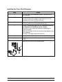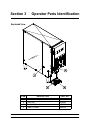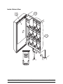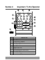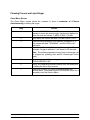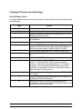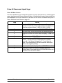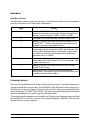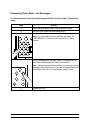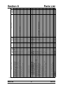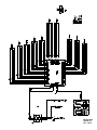
1
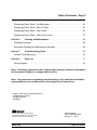
Model C006
Flavor Dispenser
Operating Instructions
066869--M
8/21/08 (Original Publication)
(Updated 8/16/12)
Complete this page for quick reference when service is required:
Taylor Distributor:
Address:
Phone:
Fax:
E-mail:
Service:
Parts:
Date of Installation:
Information found on the data label:
Model Number:
Serial Number:
Electrical Specs:
Voltage
Cycle
Phase
Maximum Fuse Size:
A
Minimum Wire Ampacity:
A
E August, 2008 Taylor (Original Publication)
All rights reserved.
066869-M
The word Taylor and the Crown design
are registered trademarks in the United States
of America and certain other countries.
Taylor Company
750 N. Blackhawk Blvd.
Rockton, IL 61072
Table of Contents
Section 1
Safety . . . . . . . . . . . . . . . . . . . . . . . . . . . . . . . . . . . . . . . . . . . . . . . . . . . .
1
Section 2
To the Installer . . . . . . . . . . . . . . . . . . . . . . . . . . . . . . . . . . . . . . . . . . . .
3
Installing the Flavor Shot Dispenser . . . . . . . . . . . . . . . . . . . . . . . . . . . . . . . . . . . . .
6
Section 3
Operator Parts Identification . . . . . . . . . . . . . . . . . . . . . . . . . . . . . . .
7
Exploded View . . . . . . . . . . . . . . . . . . . . . . . . . . . . . . . . . . . . . . . . . . . . . . . . . . . . . . . .
7
Inside Cabinet View . . . . . . . . . . . . . . . . . . . . . . . . . . . . . . . . . . . . . . . . . . . . . . . . . . .
8
Section 4
Important: To the Operator . . . . . . . . . . . . . . . . . . . . . . . . . . . . . . . . .
10
Power Switch . . . . . . . . . . . . . . . . . . . . . . . . . . . . . . . . . . . . . . . . . . . . . . . . . . . . . . . . .
11
Selection Buttons . . . . . . . . . . . . . . . . . . . . . . . . . . . . . . . . . . . . . . . . . . . . . . . . . . . . .
11
Flavor Refill and Level Reset . . . . . . . . . . . . . . . . . . . . . . . . . . . . . . . . . . . . . . . . . . .
12
Service Display Menu . . . . . . . . . . . . . . . . . . . . . . . . . . . . . . . . . . . . . . . . . . . . . . . . . .
13
Cleaning Flavors and Liquid Sugar . . . . . . . . . . . . . . . . . . . . . . . . . . . . . . . . . . . . . .
14
Cleaning All Flavors and Liquid Sugar . . . . . . . . . . . . . . . . . . . . . . . . . . . . . . . . . . .
15
Prime All Flavors and Liquid Sugar . . . . . . . . . . . . . . . . . . . . . . . . . . . . . . . . . . . . . .
16
Calibrate Flavors and Liquid Sugar . . . . . . . . . . . . . . . . . . . . . . . . . . . . . . . . . . . . . .
17
Data Menu . . . . . . . . . . . . . . . . . . . . . . . . . . . . . . . . . . . . . . . . . . . . . . . . . . . . . . . . . . .
18
Cleaning Lockout . . . . . . . . . . . . . . . . . . . . . . . . . . . . . . . . . . . . . . . . . . . . . . . . . . . . .
18
Section 5
Operating Procedures . . . . . . . . . . . . . . . . . . . . . . . . . . . . . . . . . . . . .
19
Assembly and Start Up . . . . . . . . . . . . . . . . . . . . . . . . . . . . . . . . . . . . . . . . . . . . . . . .
19
Cleaning/Sanitizing . . . . . . . . . . . . . . . . . . . . . . . . . . . . . . . . . . . . . . . . . . . . . . . . . . . .
19
Product Tube Removal/Installation . . . . . . . . . . . . . . . . . . . . . . . . . . . . . . . . . . . . . .
21
Break In Flavor (Product Tube) . . . . . . . . . . . . . . . . . . . . . . . . . . . . . . . . . . . . . . . . .
23
Table of Contents
Model C006
Table of Contents - Page 2
Dispensing Flavor Shots - Hot Beverages . . . . . . . . . . . . . . . . . . . . . . . . . . . . . . . .
24
Dispensing Flavor Shots - Box of Coffee . . . . . . . . . . . . . . . . . . . . . . . . . . . . . . . . .
25
Dispensing Flavor Shots - Iced Coffee . . . . . . . . . . . . . . . . . . . . . . . . . . . . . . . . . . .
26
Dispensing Flavor Shots - Latté (Hot or Iced) . . . . . . . . . . . . . . . . . . . . . . . . . . . . .
27
Section 6
Cleaning and Maintenance . . . . . . . . . . . . . . . . . . . . . . . . . . . . . . . . .
28
Cleaning Procedure . . . . . . . . . . . . . . . . . . . . . . . . . . . . . . . . . . . . . . . . . . . . . . . . . . .
28
Equipment Cleaning and Maintenance Schedule . . . . . . . . . . . . . . . . . . . . . . . . . .
28
Section 7
Troubleshooting Guide . . . . . . . . . . . . . . . . . . . . . . . . . . . . . . . . . . . .
29
General Troubleshooting . . . . . . . . . . . . . . . . . . . . . . . . . . . . . . . . . . . . . . . . . . . . . . .
29
Section 8
Parts List . . . . . . . . . . . . . . . . . . . . . . . . . . . . . . . . . . . . . . . . . . . . . . . . .
31
Wiring Diagram . . . . . . . . . . . . . . . . . . . . . . . . . . . . . . . . . . . . . . . . . . . . . . . . . . . . . . .
33
Note: Continuing research results in steady improvements; therefore, information
in this manual is subject to change without notice.
Note: Only instructions originating from the factory or its authorized translation
representative(s) are considered to be the original set of instructions.
E August, 2008 Taylor (Original Publication)
(Updated August, 2012)
All rights reserved.
066869-M
The word Taylor and the Crown design
are registered trademarks in the United States
of America and certain other countries.
Model C006
Taylor Company
750 N. Blackhawk Blvd.
Rockton, IL 61072
Table of Contents
Section 1
Safety
We at Taylor are concerned about the safety of the operator when he or she comes in
contact with the dispenser and its parts. Taylor has gone to extreme efforts to design and
manufacture built-in safety features to protect both you and the service technician. As an
example, warning labels have been attached to the dispenser to further point out safety
precautions to the operator.
IMPORTANT - Failure to adhere to the following safety precautions may result
in severe personal injury or death. Failure to comply with these warnings may
damage the machine and its components. Component damage will result in part
replacement expense and service repair expense.
To Operate Safely:
DO NOT operate the dispenser without reading this operator's manual. Failure to
follow this instruction may result in equipment damage, poor dispenser performance,
health hazards, or personal injury.
Per IEC 60335-1 and its part 2 standards, “This appliance is to be used only by
trained personnel. It is not intended for use by children or people with reduced physical,
sensory, or mental capabilities, or lack of experience and knowledge, unless given
supervision or instruction concerning the use of the appliance by a person responsible for
their safety.”
DO NOT operate the dispenser unless it is properly grounded. Failure to follow this
instruction may result in electrocution.
Always plug the dispenser into an approved electrical outlet. Do not touch the
dispenser with wet hands. Failure to follow this instruction may result in electrocution.
Do not immerse the dispenser in water. Failure to follow this instruction may result
in electrocution.
Observe the same safety precautions with the dispenser that you would with any
electrical appliance. Failure to follow this instruction may result in electrocution.
All repairs must be performed by a qualified service technician with the main power
supply to the dispenser disconnected. Failure to follow this instruction may result in
electrocution. Contact your local authorized Taylor Distributor for service.
120816
Model C006
1
Safety
DO NOT operate the dispenser unless all service panels and access doors are
restrained with screws. Failure to follow this instruction may result in electrocution. Contact
your local authorized Taylor Distributor for service.
DO NOT operate the dispenser with larger fuses than specified on the dispenser
data label.
Cleaning and sanitizing schedules are governed by your state or local regulatory
agencies and must be followed accordingly. Please refer to the cleaning section of this
manual for the proper procedure to clean this unit.
This unit has many sharp edges that can cause severe injuries.
DO NOT use a water jet to clean or rinse the dispenser. Failure to follow this
instruction may result in serious electrical shock.
This dispensing unit must be placed on a level surface. Use caution when moving
the unit. Failure to comply may cause the unit to tip over, and result in personal injury.
This unit is designed to operate indoors.
DO NOT obstruct air intake and discharge openings: Minimum of 1” (25.4 mm) at the rear
and 4” (102 mm) under the unit for adequate air flow.
NOISE LEVEL: This unit meets the airborne noise emission standard according to the
applicable European Directive.
If the crossed out wheeled bin symbol is affixed to this product, it signifies that this
product is compliant with the EU Directive as well as other similar legislation in effect after
August 13, 2005. Therefore, it must be collected separately after its use is completed, and
cannot be disposed as unsorted municipal waste.
The user is responsible for returning the product to the appropriate collection facility, as
specified by your local code.
For additional information regarding applicable local laws, please contact the municipal
facility and/or local distributor.
Safety
2
Model C006
Section 2
To the Installer
Overview
The flavor shot dispenser Model C006 dispenses nine flavors, combinations of flavors, and
liquid sugar products in different volumes. The dispenser is supplied with a cord and
grounding type plug. The dispenser is designed for indoor use only.
Specifications
Capacity: 9 tanks x approximately 1,000 ml.
Weight: approximately 65 lbs. (30 kg.), Crated Weight: 74 lbs. (34 kg.)
Dimensions: 24” D x 8” W x 25” H
Electrical Requirements
Electrical Requirements: 120V, AC, 15 amp., single phase, 60 Hz, supplied with NEMA
cord and plug 5-15P.
The dispenser includes a micro controller and must be operated on grounded electrical
wiring at all times. A qualified technician must complete any electrical servicing. Servicing
of the dispenser by unauthorized personnel makes the warranty null and void.
In the United States, this equipment is intended to be installed in accordance with the
National Electrical Code (NEC), ANSI/NFPA 70-1987. In all other areas of the world,
equipment should be installed in accordance with the existing local codes. Please contact
your local authorities. The purpose of the NEC code is the practical safeguarding of
persons and property from hazards arising from the use of electricity. This code contains
provisions considered necessary for safety. Compliance therewith and proper
maintenance will result in an installation essentially free from hazard!
This unit is provided with an equipotential grounding lug that is to be properly attached
to the rear of the frame by the authorized installer. The installation location is marked by
the equipotential bonding symbol (5021 of IEC 60417-1) on both the removable panel and
the equipments frame.
Stationary appliances which are not equipped with a power cord and a plug or other device
to disconnect the appliance from the power source must have an all-pole disconnecting
device with a contact gap of at least 3 mm installed in the external installation.
Appliances that are permanently connected to fixed wiring and for which leakage currents
may exceed 10 mA, particularly when disconnected or not used for long periods, or during
initial installation, shall have protective devices such as a GFI, to protect against the
leakage of current, installed by the authorized personnel to the local codes.
Model C006
3
To the Installer
Supply cords used with this unit shall be oil-resistant, sheathed flexible cable not lighter
than ordinary polychloroprene or other equivalent synthetic elastomer-sheathed cord
(Code designation 60245 IEC 57) installed with the proper cord anchorage to relieve
conductors from strain, including twisting, at the terminals and protect the insulation of the
conductors from abrasion.
FOLLOW YOUR LOCAL ELECTRICAL CODES!
CAUTION: THIS EQUIPMENT MUST BE PROPERLY GROUNDED! FAILURE TO
DO SO CAN RESULT IN SEVERE PERSONAL INJURY FROM ELECTRICAL SHOCK!
DO NOT attempt any repairs unless the main power supply to the dispenser has
been disconnected.
DO NOT install this equipment in an area where a water jet could be used. Failure
to follow this instruction may result in severe personal injury from electrical shock.
To the Installer
4
Model C006
Air Clearance
Always allow a minimum of 1” (25.4 mm) at the rear and 4” (102 mm) under the unit for
adequate air flow.
Warranty
One year parts and labor, excluding wear items.
CAUTION: Warranty is valid only if required service work is provided by an Authorized
Taylor Service Technician.
Note: Warranty is valid only if the parts are authorized Taylor parts, purchased from an
authorized Taylor Distributor, and the required service work is provided by an authorized
Taylor service technician. Taylor reserves the right to deny warranty claims on equipment
or parts if non-approved parts were installed in the machine, system modifications were
performed beyond factory recommendations, or it is determined that the failure was
caused by neglect or abuse.
IMPORTANT: The unit must be cleaned, primed and calibrated prior to the first use.
ALL flavors and the sugar must be calibrated at time of start up. It is NOT optional
to calibrate only one or two flavors. If these procedures are not followed completely, the
CUSTOM (combination) selector button will not operate.
Model C006
5
To the Installer
Installing the Flavor Shot Dispenser
Step
Action
1
Place the flavor shot dispenser where it will best serve
your operation.
2
Make sure that counters, platforms, and shelves are strong
enough to support the weight of the dispenser and full
containers of product (109 lbs. [49 kg.]).
3
Maintain a minimum of 1” (25.4 mm) at the rear and 4”
(102 mm) under the unit for adequate air flow.
4
DO NOT remove the legs from the dispenser or allow
the dispenser to sit directly on the counter.
Adequate air flow under the machine is necessary for
proper operation.
Make sure the legs at the four corners of the dispenser are
firmly attached.
Removal of the legs violates the warranty.
5
Make sure the unit is level.
6
Plug the power cord into the proper electrical outlet (NEMA
5-15P).
7
Install the drip tray and the splash shield.
To the Installer
6
Model C006
Section 3
Operator Parts Identification
Exploded View
ITEM
1
2
3
4
Model C006
DESCRIPTION
Switch-Rocker (Power Switch)
Tray-Drip
Shield A.-Splash
Tube A.-Outlet
7
PART NO.
048093
058346
X59366
X59334
Operator Parts Identification
Inside Cabinet View
2
3
1
MAX. FILL LINE
LOW LEVEL
Operator Parts Identification
8
Model C006
Inside Cabinet View Identification
ITEM
1
2
3
DESCRIPTION
ABBREVIATION
Syrup Tank
Cover-Tank Mix
Decal-Mag-Instruction
-----
PART NO.
062244059133
059532-TAY
IMPORTANT:
There are nine individual flavor tanks. The tanks must be placed in their
proper locations to correspond with current software and display
characteristics.
All flavors are subject to change at any time.
Model C006
9
Operator Parts Identification
Section 4
ITEM
1
2
3
4
5
6
7
8
9
10
11
12
13
Important: To the Operator
DESCRIPTION
Power Switch
Flavor Buttons
Product Buttons / Calibration
Size Buttons / Calibration
Promo Portion Button
Box of Coffee Button
Sugar Button
Indicator Lights (LED)
LCD Screen
Clean/Calibrate Button (Service Menu)
Preset Combo Buttons
Custom Flavor Button
Power Indicator (LED)
Important: To the Operator
10
Model C006
Power Switch
When the unit is plugged into a receptacle and the power switch is placed in the ON
position, the power indicator light will illuminate. The power switch is left in the ON position
during normal operations.
Selection Buttons
Flavor Shot Buttons
There are nine flavor shot buttons. When a particular flavor shot is selected, the light above
that button will illuminate.
Note: All flavors are subject to change at any time.
SUG (Sugar) Button
When liquid sugar is selected, the light above that button will illuminate. Press the SUG
button, and then the appropriate size, to dispense the liquid sugar. The sugar button works
independently of the flavor shot selections.
Recipe Buttons
When a particular product is selected, the light above that button will illuminate.
ICED COFFEE
LATTÉ/CAP
FUTURE
FUTURE
FUTURE
Size Buttons
When a particular portion size is selected, the product will dispense.
X-SM
SM
MED
LG
X-LG
PROMO
BOX
Model C006
=
=
=
=
=
=
=
Extra Small
Small
Medium
Large
Extra Large
Promotional or Future
Box of Coffee
11
Important: To the Operator
Flavor Refill and Level Reset
When a MIX LOW condition is present, the flavor indicator will flash at 1/2 second intervals
and at 1/4 second intervals when a MIX OUT is present. When a MIX OUT condition is
present, that specific flavor will lock out until it is refilled and reset.
Each flavor can be reset individually at the full or low fill level: Full = HI (586 ml) and Low
Fill = LO (195 ml).
Full Level: The operator may reset the level by filling the tank to the fill line and pressing
and holding that specific flavor for 3 seconds. Upon reset, the LED will stop flashing and
will be reset to sense a full tank (HI). The LCD will display “REFILLED HI XX” with the
appropriate flavor (XX) abbreviation indicated for 4 seconds. The screen will automatically
return to normal operation.
Low Fill Level: While the screen is reading “REFILLED HI XX”, the operator can press the
same flavor button to set the control to the “LO” level. The operator may toggle between
HI and LO, but once the flavor button has not been pressed for 4 seconds, the control is
set for that level. The control will now be in the normal mode of operation.
The control can be reset and refilled prior to a MIX LOW or MIX OUT condition.
IMPORTANT: Any time a flavor is reset, be sure that the appropriate tank has been
refilled to the fill line.
Liquid Sugar Refill: When a MIX LOW condition is present, the liquid sugar indicator will
flash at 1/2 second intervals and at 1/4 second intervals when a MIX OUT is present.
Replace the liquid sugar container with a full container and insert the sugar feed tube.
Prime the sugar line by pressing the SUG (liquid sugar) button once and then pressing the
“Box of Coffee” button once. Reset the refill level by pressing and holding the SUG button
for 3 seconds.
Note: The LED's are above the flavor buttons. The LCD display is under the SUG button.
Important: To the Operator
12
Model C006
Service Display Menu
The Service Display Menu provides several screens to the operator and technician for setup, monitoring and evaluation.
To enter the Service Display Menu, press the CLEAN/CAL button. The screen will prompt
the operator to enter the access code. Use the product size buttons to enter the code as
follows: 3 (MED) 2 (SM) 1 (X-SM). Once the Service Display Menu is entered, the following
screens are available in the order shown. Cycle through the screens by pressing the
CLEAN/CAL button.
1. CLEAN PRESS FLVR = Clean
2. CLEAN ALL <1>
= Clean All Tanks
3. PRIME ALL <1>
= Prime All Tanks
4. CAL PRESS FLVR
= Calibrate (Must be performed at Start-up or unit will not
dispense.)
5. BREAK IN
= Break In New Product Tube
6. DATA PRESS PR/FL
= Data
To exit the Service Menu, press and hold the CLEAN/CAL button for 3 seconds and
release. Note: The display will read “COFFEE”.
Model C006
13
Important: To the Operator
Cleaning Flavors and Liquid Sugar
Clean Menu Screen
The Clean Menu screen allows the operator to clean a maximum of 4 flavors
simultaneously, including the sugar.
Action
Step
1
Press the CLEAN/CAL button. The screen will prompt the
operator to enter the access code. Use the size buttons to
enter the code as follows: 3 (MED) 2 (SM) 1 (X-SM).
2
Upon entry, the screen will read “CLEAN PRESS FLVR”.
3
Press the flavor button(s) to be cleaned (maximum of 3).
The screen will read “CLEANING”, and the LED(s) will
illuminate.
4
The selected flavor(s) will clean simultaneously for 50
seconds. If sugar is selected, it will clean for 50 seconds.
Note: The cleaning operation for any flavor or the sugar can
be stopped by pressing that specific flavor/sugar button
again.
5
Upon completion of the cleaning, the screen will return to
“CLEAN PRESS FLVR”.
6
Empty any remaining sanitizer/cleaner from the tanks prior
to adding the flavor shot product.
7
Press the CLEAN/CAL button to advance within the
Service Menu. Press and hold the CLEAN/CAL button for 4
seconds to exit the Service Menu.
Important: To the Operator
14
Model C006
Cleaning All Flavors and Liquid Sugar
Clean All Menu Screen
The Clean All Menu screen allows the operator to clean all the flavors and the liquid sugar
simultaneously.
Action
Step
Model C006
1
Remove the flavor tanks from the unit.
2
Clean the inside of the unit with a clean, damp cloth.
3
Prepare 4 cleaning containers with an approved 100 PPM
cleaning/sanitizing solution.
4
Place one container on each shelf with the product tubes in
the containers.
5
Place the sugar feed tube in the fourth container.
6
Press the CLEAN/CAL button. The screen will prompt the
operator to enter the access code. Use the size buttons to
enter the code as follows: 3 (MED) 2 (SM) 1 (X-SM).
7
Upon entry, the screen will read “CLEAN PRESS FLVR”.
8
Press the CLEAN/CAL button once to display “CLEAN ALL
<1>”.
9
Press the “1” (X-SM) button.
10
The display will read “CLEANING”.
Flavors 1 - 3 will clean first. When they are complete,
flavors 4 - 6 will clean, followed by flavors 7 - 9, and then
the sugar. The corresponding LED will illuminate while
each flavor or the sugar is cleaning. (Each flavor and the
sugar will clean for 50 seconds.)
11
Upon completion, the display will return to the “CLEAN ALL
<1>” screen.
12
Empty any remaining sanitizer/cleaner from the tanks prior
to adding the flavor shot product.
13
Press the CLEAN/CAL button to advance within the
Service Menu. Press and hold the CLEAN/CAL button for 4
seconds to exit the Service Menu.
15
Important: To the Operator
Prime All Flavors and Liquid Sugar
Prime All Menu Screen
The Prime All Menu screen allows the operator to prime all of the flavors, including liquid
sugar, simultaneously. Be sure that every flavor, including liquid sugar, being primed has
been refilled to the fill line indicated on the tank and the control has been reset (refer to
Flavor Refill and Level Reset on page 12.
Step
Action
1
Press the CLEAN/CAL button. The screen will prompt the
operator to enter the access code. Use the size buttons to
enter the code as follows: 3 (MED) 2 (SM) 1 (X-SM).
2
Upon entry, the screen will read “CLEAN PRESS FLVR”.
3
Place an empty coffee cup beneath the dispensing spout.
4
Press the CLEAN/CAL button twice to display “PRIME ALL
<1>”.
5
Press the number “1” (X-SM) button.
6
The display will read “PRIMING”.
Flavors 1 - 3 will prime first. When they are complete,
flavors 4 - 6 will prime, followed by 7 - 9, and then the
sugar. The corresponding LED will illuminate while each
flavor or the sugar is priming.
7
Upon completion, the display will read “PRIME ALL <1>”.
8
Press the CLEAN/CAL button to advance within the
Service Menu. Press and hold the CLEAN/CAL button for 4
seconds to exit the Service Menu.
Important: To the Operator
16
Model C006
Calibrate Flavors and Liquid Sugar
Calibrate Menu Screen
The Calibrate Menu screen allows the operator to calibrate and dispense volume for each
flavor and liquid sugar. IMPORTANT: Calibration is by weight, NOT volume.
Step
Action
1
Place a scale under the dispensing spout and place an
empty cup on the scale. Reset the scale to “000”.
2
Press the CLEAN/CAL button. The screen will prompt the
operator to enter the access code. Use the size buttons to
enter the code as follows: 3 (MED) 2 (SM) 1 (X-SM).
3
Upon entry, the screen will read “CLEAN PRESS FLVR”.
4
Press the CLEAN/CAL button three times to display “CAL
PRESS FLVR”.
5
Press the flavor in need of calibration. The screen will
read; example: “CAL 100.00 GM”.
6
Check the amount dispensed displayed on the scale
“XXX.X” and enter it onto the dispenser using the numeric
buttons 0-9 listed under the size and recipe buttons.
7
Once the last digit has been entered, press the
CLEAN/CAL button once to return to the CAL PRESS
FLVR screen.
Note: Proper calibration may take more than one attempt.
8
Repeat steps 5 - 7 until the flavor being calibrated is within
± 5% of the 100 grams (95.0 - 105.0 grams).
9
Repeat steps 5 - 8 for all flavors in need of calibration.
IMPORTANT: The unit must be cleaned, primed and calibrated prior to the first use.
ALL flavors and the sugar must be calibrated at time of start up. It is NOT optional
to calibrate only one or two flavors. If these procedures are not followed completely, the
CUSTOM (combination) selector button will not operate.
Model C006
17
Important: To the Operator
Data Menu
Data Menu Screen
The Data Menu screen allows the operator to view the total number of cycles completed
since the last reset for a product flavor combination.
Action
Step
1
Press the CLEAN/CAL button. The screen will prompt the
operator to enter the access code. Use the size buttons to
enter the code as follows: 3 (MED) 2 (SM) 1 (X-SM).
2
Upon entry, the screen will read “CLEAN PRESS FLVR”.
3
Press the CLEAN/CAL button five times to display “DATA
PRESS PR/FL”. Coffee is the default product and can be
changed by pressing any product button.
4
Press the selected product/flavor combination. The
corresponding flavor and product LED's will illuminate. The
product will be displayed up to 6 characters, a space and
the number of cycles for the flavor/product combination
dispensed from 0 to 65000.
5
To reset the selected product/flavor counter, the operator
should press and hold the flavor button for 4 seconds. The
counter will reset to 0.
6
Press the CLEAN/CAL button to return to the “CLEAN
PRESS FLVR” screen.
7
Press the CLEAN/CAL button to advance within the
Service Menu. Press and hold the CLEAN/CAL button for 4
seconds to exit the Service Menu.
Cleaning Lockout
This unit is manufactured with a 60 day lockout cleaning feature. To minimize the amount
of product discarded in this process, the CLEAN/CAL light will flash for three days prior to
the 60th day. At the end of day 60, the unit will lockout (no dispensing allowed) and the
screen will display “LOCKED FOR CLEAN”. At that time any remaining product in the tanks
must be discarded prior to performing the cleaning process.
To unlock the unit the operator must clean the unit. After the unit is cleaned, press and hold
the “CLEAN/CAL” button for 4 seconds. The screen will display “CLEANED” for 4 seconds
and will clear for normal operation.
Important: To the Operator
18
Model C006
Section 5
Operating Procedures
Assembly and Start Up
Step
Action
1
Plug the machine into an approved receptacle. The power
indicator will illuminate on the front of the dispenser.
2
Open the front door to the dispenser.
3
Remove all tanks and lids.
ALWAYS FOLLOW LOCAL HEALTH CODES!
Cleaning/Sanitizing
Step
Model C006
Action
1
Prepare a sink with an approved 100 PPM
cleaning/sanitizing solution (example: Kay-5® or Stera
Sheen®). USE WARM WATER AND FOLLOW THE
MANUFACTURER'S SPECIFICATIONS.
2
Thoroughly wash, rinse, and sanitize all tanks and lids in
the sink.
3
Prepare 3 cleaning containers with an approved 100 PPM
cleaning/sanitizing solution.
4
Place one container on each shelf with product tubes in the
containers.
5
Prepare another cleaning container of cleaning/ sanitizing
solution.
6
Place the sugar feed tube in the cleaning/sanitizing
solution.
7
Press the CLEAN/CAL button. The screen will prompt the
operator to enter the access code. Use the size buttons to
enter the code as follows: 3 (MED) 2 (SM) 1 (X-SM).
8
Upon entry, the screen will read “CLEAN PRESS FLVR”.
9
Press the CLEAN/CAL button once to display “CLEAN ALL
<1>”.
19
Operating Procedures
Cleaning/Sanitizing (Continued)
Step
Action
10
Press the “1” (X-SM) button to begin cleaning. The three
flavors corresponding to the top row of flavor keys will
clean first. Upon completion, the three flavors in the next
row will clean, followed by the three flavors in the last row,
and then the SUG (liquid sugar). The cleaning procedure
will take approximately four minutes.
11
Remove and discard any cleaning/sanitizing solution
remaining in the cleaning containers.
12
Remove the sugar feed tube from the cleaning/sanitizing
solution and allow it to drain.
13
Install the sugar feed tube in the liquid sugar container.
Operating Procedures
20
Model C006
Product Tube Removal/Installation
Step
Model C006
Action
1
Discard any remaining product in the tank.
2
Wash and rinse the tank and the lid.
3
Fill the tank with clean water to the fill line on the tank.
4
Place a cup under the dispensing spout.
Note: Refer to the “Clean Flavors and Liquid Sugar”
instructions within the Service Menu on page 14.)
5
Activate the flavor selection corresponding to the product
tube in need of replacement. This will pump the water from
the tank and tube.
6
Remove the product tank.
7
Place the dispenser power switch in the OFF position.
8
Unplug the dispenser from the wall receptacle.
9
Remove the right side panel.
10
Carefully open the pump cover.
11
Remove the product tube from the stainless tubes.
12
Install the new product tube onto the stainless steel tubes.
13
Route the product tube through the pump. (Be sure to
route the tube properly. The pumps are directional.)
14
Carefully align the product tube, making sure the tube is
centered over the pump rollers.
15
Press down on the tube at both ends to remove slack and
carefully close the pump cover. Make sure there are no
kinks and that the tube stays centered over the rollers.
21
Operating Procedures
Product Tube Removal/Installation (Continued)
Step
Action
16
Follow the Break In Flavor instructions starting on page 23
for the flavor line that was replaced.
17
Refer to Cleaning Flavors and Liquid Sugar on page14.
Note: To minimize or eliminate any mistakes when replacing and installing a new tube,
remove and replace one tube at a time.
Operating Procedures
22
Model C006
Break In Flavor (Product Tube)
Model C006
Step
Action
1
Prepare a cleaning container with an approved 100 PPM
cleaning/sanitizing solution (example: Kay-5® or Stera
Sheen®). USE WARM WATER AND FOLLOW THE
MANUFACTURER'S SPECIFICATIONS.
2
Remove all three syrup tanks from the shelf containing the
tank with the new product tube.
3
Place the cleaning container on the shelf and insert the
product tubes in the container.
4
Press the CLEAN/CAL button to display the screen that
prompts the operator to enter the access code.
5
Using the size buttons, enter access code: 3 (MED) 2 (SM)
1 (X-SM). Upon entry, the screen will read “CLEAN PRESS
FLVR”.
6
Press the CLEAN/CAL button four times until the screen
displays “BREAK IN FLVR”.
7
Press the appropriate flavor button.
8
The pump will run for 2-1/2 minutes and automatically shut
off.
9
Repeat steps 1, 3, and 7. The pump will run for another
2-1/2 minutes and automatically shut off.
10
Remove and discard any cleaning/sanitizing solution
remaining in the cleaning container.
11
Wipe the interior of the cabinet with a clean, damp cloth.
12
Reinstall the syrup tanks in their appropriate positions.
13
Reprime all three syrup lines as follows: In the standard
operator mode, select the appropriate flavor button and
then the “small” button. Repeat this procedure twice for
each flavor to eliminate air pockets in the line.
14
Calibrate the flavor that received the new product tube.
(See page 17.)
23
Operating Procedures
Dispensing Flavor Shots - Hot Beverages
To dispense flavor shots for hot beverages (Coffee, Hot Chocolate), follow these
steps:
Step
Action
1
Select the appropriate cup for the customer's order.
2
Place the cup under the dispensing spout.
3
Press the flavor button.
Note: If a combination flavor is desired, first press the
CUSTOM button. Then press the desired 2 or 3 flavor
buttons.
4
Press the appropriate cup size button. (Pressing the cup
size button will dispense the flavor shot product.)
Note: After pressing the flavor button, you have up to three
seconds to press the cup size. If you do not press the cup size
within three seconds, you must repeat steps 3 and 4.
5
Operating Procedures
Remove the cup.
24
Model C006
Dispensing Flavor Shots - Box of Coffee
To dispense the flavor shots for the box of coffee, follow these steps:
Model C006
Step
Action
1
Place a small coffee cup under the dispensing spout and
press the flavor button.
2
Press the Box of Coffee button. This will dispense the
proper amount of the flavor shots for the coffee.
3
Place a funnel on the box of coffee. Pour the flavor shots
from the coffee cup into the box of coffee.
4
Fill the box of coffee with 108 oz. of coffee.
25
Operating Procedures
Dispensing Flavor Shots - Iced Coffee
To dispense the flavor shots for Iced Coffee, follow these steps:
Step
Action
1
Select the appropriate cup for the customer's order.
2
Fill the cup 2/3 full with ice.
3
Place the cup under the dispensing spout.
4
Press the flavor button.
13497
Note: If a combination flavor is desired, first press the
CUSTOM button. Then press the desired 2 or 3 flavor
buttons.
5
Press the ICE COFF button.
6
Press the appropriate cup size button. (Pressing the cup
size button will dispense the flavor shot product.)
Operating Procedures
26
Model C006
Dispensing Flavor Shots - Latté (Hot or Iced)
To dispense the flavor shots for Latté drinks, follow these steps:
Step
Action
1
Select the appropriate cup for the customer's order.
2
Fill the cup 2/3 full with ice.
Note: Skip this step for hot Latté.
Model C006
3
Place the cup under the dispensing spout.
4
Press the flavor button.
Note: If a combination flavor is desired, first press the
CUSTOM button. Then press the desired 2 or 3 flavor
buttons.
5
Press the LATTE/CAP button.
6
Press the appropriate cup size button. (Pressing the cup
size button will dispense the flavor shot product.)
27
Operating Procedures
Section 6
Cleaning and Maintenance
Cleaning Procedure
ALWAYS FOLLOW LOCAL HEALTH CODES!
To disassemble and clean the unit, the following items will be needed:
S Brushes (provided)
S Cleaner/Sanitizer (example: Kay-5® or Stera Sheen®)
S Single service hand towels
Equipment Cleaning and Maintenance Schedule
Function
Procedure
Frequency
Initial Flavor Fill
Reset the level for each flavor.
After cleaning tanks
Flavor Refill
Reset the level for each flavor.
After adding product to
tanks (full or low fill level)
Prime
Prime All.
After cleaning tanks
Calibrate
Calibrate each flavor.
Weekly and after cleaning
tanks.
Wipe the outside of the machine
down with a clean, sanitized towel.
Daily Cleaning
Use a brush to clean the
dispensing spout.
Daily
Wash, rinse and dry the drip tray.
Perform a complete machine
breakdown.
Dispose of all existing product.
Sixty Day Cleaning
Wash, rinse, and sanitize tanks.
Perform cleaning procedure.
Reset the cleaning cycle by holding
the Clear/Cal button for 4 seconds.
Every 60 days.
101005
Cleaning and Maintenance
28
Model C006
Section 7
Troubleshooting Guide
General Troubleshooting
Problem
1. Dispenser will not
operate.
2. Dispenser will not
dispense product.
Model C006
Probable Cause
Remedy
a. Unit is not plugged in.
a. Plug the unit into a
receptacle.
b. Power switch is in the
OFF position.
b. Place the power switch
in the ON position. The
power indicator light will
illuminate.
a. There is no product in
the unit; i.e., there is a
MIX OUT condition.
a. Add product to the fill
line and reset (full or
low fill level). Full = HI
(586 ml) and Low Fill =
LO (195 ml).
b. The product tube is
obstructed or kinked.
b. Clear the obstruction or
kink.
c. The product tube is not
properly aligned over
the pump rollers.
c. Realign the product
tube, centering it over
the pump rollers and
removing any slack.
(See page 21.)
d. Unit is in the 60 day
lockout.
d. Clean the unit. Then
press and hold the
CLEAN/CAL button for
4 seconds to reset the
cleaning cycle.
29
Troubleshooting Guide
Problem
3. An improper amount of
product is being
dispensed.
Probable Cause
Remedy
a. Incorrect calibration.
a. Re-calibrate.
b. The product tube is
obstructed or kinked.
b. Clear the obstruction or
kink.
c. The product tube is not
properly aligned over
the pump rollers.
c. Realign the product
tube, centering it over
the pump rollers and
removing any slack.
(See page 21.)
d. The unit was improperly
reset.
d. Fill the tank to the fill
line and reset (full or
low fill level). Full = HI
(586 ml) and Low Fill =
LO (195 ml).
e. The product tube is
damaged.
e. Replace the tube.
If assistance or service is needed, please contact your local Taylor Distributor.
Troubleshooting Guide
30
Model C006
Model C006
BOARD-CONTROL-FLAVOR SHOT
BRUSH-DBL END-PUMP & FEED
BRUSH-DRAW VALVE 1-1/2”OD
BRUSH-END-DOOR-SPOUT-SS-H
CABLE-INTERFACE/CONTROL *C006*
CAP-ULTIMATE SYRUP
CORD-POWER-125V-15A-95”LCOVER-TANK MIX *C006*
DOOR A.-FRONT *C006*
CONTROL-TOUCH SCREEN W/DECAL
GASKET-DOOR-FRONT *C006*
HINGE-DOOR *C006*
HINGE-DOOR *C006*
+PLATE A.-HINGE MOUNTING *
SCREW-10-32X3/8 RHM-SS
SCREW-8-32X3/16 SS RHM
HARNESS-WIRE-POWER/CTRL *C006
HARNESS-WIRE-PUMP MOTOR/CTRL *C006
LABEL-MAG-CONTROL C006
LEG-4” 3/8-16 STUD-PLASTI
MOTOR-GEAR 400 RPM
PANEL A.-DOOR *C006*
PANEL-SIDE-RIGHT LOWER *C006
PANEL A.-LEFT FRONT *C006*
PANEL-SIDE-LEFT LOWER *C0
PUMP-PERISTALTIC 3.2MMIDX
PUMP-PERISTALTIC 6.4MMIDX
SHIELD A.-SPLASH *C006*
SUPPLY-POWER 72W 24DC
SWITCH-ROCKER *370*POWER/
TANK-MIX
DESCRIPTION
058542-SER
013072
014753
039719
059140
053040-WHT
042936-12
059133
X58578
059086-SER
062263
059340
059340
X59321
006749
017551
059139
062268
059470024755
062269-05
X59089
058518
X59319
058530
058545-1
058545-2
X59366
059313-12
048093
062244-
PART
NUMBER
1
1
1
1
1
1
1
9
1
1
1
1
2
2
4
4
1
1
1
4
10
1
1
1
1
9
1
1
2
1
1
QTY.
103
000
000
000
000
000
103
103
103
103
000
000
000
000
000
000
103
103
000
103
103
103
103
103
103
103
103
103
103
103
103
WARR.
CLASS
31
SUGAR
FRONT
FRONT/BLACK FLAVOR SELECT
GREY SLEEVE/DOOR
REMARKS
PARTS
UPDATE
Section 8
Parts List
+ Available Separately
Parts List
100712
+ Available Separately
Parts List
32
Model C006
TANK-MIX 2 *C006*
TANK-MIX 3 *C006*
TRAY-DRIP *C006*
TUBE A.-OUTLET *C006*
TUBE A.-SUCTION-RIGHT *C006
TUBE-PUMP-PERIS-2.4MMIDX2
TUBE A.-SUCTION-MIDDLE *C006
TUBE-PUMP-PERIS-2.4MMIDX2
TUBE A.-SUCTION-LEFT *C006
TUBE-PUMP-PERIS-2.4MMIDX2
TUBE A.-SYRUP PICK UP
TUBE-PUMP-PERIS-6.4MMIDX2
DESCRIPTION
062244-11
062244-12
058346
X59334
X59529
067120-10
X59530
067120-10
X59531
067120-10
X53175
059152-60
PART
NUMBER
1
1
1
1
3
3
3
3
3
3
1
1
QTY.
103
103
103
103
000
000
000
000
000
000
103
000
WARR.
CLASS
1-16-04 & Up
Length changed from 15” to 10” 1-16-04
1-16-04 & Up
Length changed from 20” to 10” 1-16-04
1-16-04 & Up
Length changed from 25” to 10” 1-16-04
REMARKS
PARTS
UPDATE
Model C006
059359-12
Rev. 10/10