1
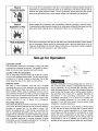
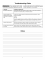
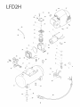
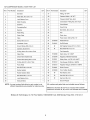
TASK
Item #83691
FORCE
Air Compressor
Electric Handheld
2 gallons
100 max psi
120 VAC -- 15 amp minimum circuit
Includes: 25 ft nylon coil hose and 17 pc accessory
kit
OWNER'S MANUAL
and Parts List
,,
For customer service, contactq
1-800-628-8815
ext. 5000
J
WARNING!
_,
ead and understand all safety precautions
this portable air compressor.
and operating
instructions
before
using
Midwest Air Technologies, Inc., 625 Barclay Boulevard, Lincolnshire, IL 60069
1/12/03
Task Force® is a registered trademark of LF, LLC. All Rights Reserved
Part No. E100186
Rev.01
TABLE OF CONTENTS
Page
Safety Definitions ..................................................................................................
3
Glossary ................................................................................................................
3
Duty Cycle ............................................................................................................
3
Description of Operation .......................................................................................
3
Important Safety Instructions & Guidelines ..........................................................
4
Set-up for Operation
............................................................................................
5
Operating Procedures ...........................................................................................
6
Maintenance .........................................................................................................
6
Routine Maintenance Schedule ............................................................................
6
Storage ..................................................................................................................
6
Troubleshooting
Guide ..........................................................................................
7
Exploded Parts Diagram ......................................................................................
8
Parts List ..............................................................................................................
9
Limited Warranty ..................................................................................................
10
Safety Definitions
The information
listed below should
be read and
understood
by the operator. This information is
given to protect the user while operating
and
storing the air compressor. We utilize the symbols
below to allow the reader to recognize important
information about their safety.
Indicates an imminently hazardous situation which, if
not avoided, will result in death or serious injury.
Indicates a potentially hazardous situation which, if not
avoided, may result in minor or moderate injury.
Indicates a potentially hazardous situation which, if not
avoided, could result in death or serious injury
When used without the safety alert symbol indicates a
potentially hazardous situation which, if not avoided,
may result in property damage.
Glossary
CFM:
Cubic feet per minute.
SCFM: Standard cubic feet per minute; a unit of measure
for air delivery.
PSlG:
Pounds per square inch gauge; a unit of measure
for pressure.
ASME: American
Society
of
Mechanical
Cut-In Pressure:
The air compressor will automatically
start to refill the tank when the pressure drops
below the prescribed minimum.
Cut-Out Pressure:
The point at which the motor stops
when the tank has reached maximum air pressure.
Code Certification:
Engineers.
Products that bear one or more of
the following marks: UL, ETL or CSA have
been evaluated by OSHA certified independent
safety laboratories
and meet the applicable
Underwriters Laboratories Standards for Safety.
California Code: Unit may comply with California Code
462 (I) (2)/(M) (2).
Duty Cycle
This air compressor pump should not run more than
20 minutes per hour. If the pump runs more than
30% of the duty cycle, the air requirement is greater than
that which is supplied by the unit. You may need to check
for restrictions in the air line, use a larger diameter hose, or
purchase an air compressor that better matches your air
requirements.
Description of Operation
Drain Valve: Used to drain condensation from the air tank.
Located at bottom of tank.
Fan Cooled: This unit is equipped with a cooling fan
which may continue to run after the pump has stopped.
On/Off Switch: This controls the power to the motor and
also the switch serves as the on/off positions for the air
compressor.
Air Intake Vents: Provide clean air to the pump and must
always be kept free of debris. Check on a daily basis or
before each use.
Air Compressor
Pump: Pressurizes
air
atmosphere and stores it in a reserve tank.
from
the
Tank Safety Valve: Used to allow excess tank pressure to
escape into the atmosphere. This valve should only open
when the tank pressure is above the maximum rated
pressure of the model.
Regulator Pressure Gauge: Indicates the outgoing
pressure to the tool and is controlled by the regulator.
air
Tank Pressure Gauge: Indicates the reserve air pressure
in the tank.
Regulator: Controls the pressure leaving the air tank.
Tools require different operating pressures. Refer to the tool
manufacturers manual before connecting to the compressor. To increase the pressure turn the knob clockwise and
to decrease the pressure turn the knob counterclockwise.
Important Safety Instructions and Guidelines
• Save all instructions
Improper operation or maintenance
of this product could result in serious
injury and/or property damage. Read and understand all
•
of the warnings and safety instructions provided before
using this equipment.
The air compressor should be operated on a dedicated 15 amp circuit. If the circuit does
not have 15 free amps available, a larger circuit must be used. Always use more air hose
before utilizing extension cords. All extension cords used must be 12 gauge with a
maximum length of 25 ft. The circuit fuse type must be a time delay. Low voltage could
cause damage to the motor. Always have adequate space (12 inches) on all sides of the
air compressor. Spraying paint and other materials will always need to be in another
area away from the air compressor to prevent damage to the air compressor filter. If spraying flammable materials, locate compressor at least 20 feet away from spray area. An
additional length of hose may be required. Store flammable materials in a secure location away from compressor.
Risk of Moving
Parts
I
i
i
i
If the air compressor is in operation, all guards and covers should be attached or
installed correctly. If any guard or cover has been damaged, do not operate the
equipment until authorized personnel have correctly repaired the equipment. The power
cord should be free of any moving parts, twisting and/or crimping while in use and while
in storage. Do not operate this equipment without all guards properly installed.
I
Risk of Burns
There are surfaces on your air compressor that can cause serious burns if touched. The
equipment should be allowed time to cool before any maintenance is attempted. Items
such as the compressor pump and the outlet tube are normally hot during and after
operation.
Risk of Falling
Operation of the air compressor should always be in a position that is stable. Never use
the air compressor on a rooftop or elevated position that could allow the unit to fall or be
tipped over. Use additional air hose for elevated jobs.
I
I
Risk from
Flying Objects
Always wear ANSI Z87.1 approved safety glasses with side shields when the air
compressor is in use. Turn off the air compressor and drain the air tank before
performing any type of maintenance or disassembly of the hoses or fittings. Never point
any nozzle or sprayer toward any part of the body or at other people or animals.
Risk to Breathing
Avoid using the air compressor in confined areas. Also keep children, pets, and others
out of the area of operation. This air compressor does not provide breathable air for
anyone or any auxiliary breathing device.
i
Risk of
Electrical Shock
Do not use the air compressor in the rain or wet conditions. Electrical repairs should be
performed by authorized personnel such as an electrician and should comply with all
national and local electrical codes. The air compressor should also have the proper
three prong grounding plug, correct supply voltage, and adequate fuse protection.
Risk of
Never operate the compressor near combustible materials, gasoline or solvent vapors.
If spraying flammable materials, locate the air compressor at least 20 feet away from the
spray area. Never operate the air compressor indoors or in a confined area.
Explosion
or Fire
Risk of Bursting
Drain the air compressor tank daily or after each use. If the tank develops a leak, replace
the air compressor. Never use the air compressor after a leak has been found or try to
make any modifications to the tank. Never modify the air compressor's factory settings
which control the tank pressure or any other function.
Set-up for Operation
Lubrication and Oil
This compressor requires no lubrication or oiling. No break
in procedure is required by the user. This product is factory
tested to ensure proper operation and performance.
Location of the Air Compressor
The air compressor should always be located in a clean,
dry, and well ventilated environment. The unit should have,
a minimum of 12 inches of space on each side. The air filter
intake should be free of any debris or obstructions.
Extension Cords
Use only a 3-wire extension cord that has a 3-blade
grounding plug, and a 3-slot receptacle that will accept the
plug on the product. Make sure your extension cord is in
good condition. When using an extension cord, be sure to
use one heavy enough to carry the current your product will
draw. Cords must not exceed 25 feet and No. 12 AWG size
must be used. An undersized cord will cause a drop in line
voltage resulting in loss of power and overheating.
Grounding Instructions
This product should be grounded. In the event of an electrical
short circuit, grounding reduces the risk of electric shock by
providing an escape wire for the electric current. This
product is equipped with a cord having a grounding wire
with an appropriate grounding plug. The plug must be
plugged into an outlet that is properly installed and grounded
in accordance with all local codes and ordinances. Check
with a qualified electrician or service personnel if these
instructions are not completely understood or if in doubt as
to whether the tool is properly grounded.
Plug
ii _
Grounded
Outlet
Grounding Pin
Improper installation of the grounding plug can result in a
risk of electric shock. If repair or replacement of the cord or
plug is necessary, do not connect the grounding wire to
either flat blade terminal. The wire with insulation having an
outer surface that is green with or without yellow stripes is
the grounding wire. Check with a qualified electrician or
serviceman
if the grounding
instructions
are not
completely understood, or if in doubt as to whether the
product is properly grounded. Do not modify the plug
provided; if it will not fit the outlet, have the proper outlet
installed by a qualified electrician.
This product is for use on a circuit having a nominal rating
of 120 volts and is factory-equipped with a specific electric
cord and plug to permit connection to a proper electric
circuit. Make sure that the product is connected to an outlet
having the same configuration as the plug. No adapter
should be used with this product. If the product must be
reconnected for use on a different type of electric circuit,
qualified service personnel should make the reconnection.
Operating Procedures
Daily Start-Up Procedures
1. Set the On/Off switch to the Off position.
2. Check the air compressor visually for any damage or
obstruction.
3. Close the drain valve.
4. Plug the power cord into the proper receptacle.
5. Turn the On/Off switch to the On position and the
compressor should start and build air pressure in the
tank to cut-out pressure and then shut off automatically.
6. Adjust the regulator to a PSI setting that is recommended
for your application.
7. The air compressor is now ready for use.
When draining the tank, always use ear and eye protection.
Drain the tank in a suitable location; condensation will be
present in most cases of draining.
5. Open the drain valve allowing air to bleed from the tank.
After all of the air has bled from the tank, close the drain
valve to prevent debris buildup in the valve.
Water that remains in the tank during storage will corrode
and weaken the air tank which could cause the tank to
rupture. Please be sure to drain the tank after each use or
daily.
Daily Shut-Down Procedures
1. Set the On/Off switch to the Off position.
2. Unplug the power cord from the receptacle.
3. Set the outlet pressure to zero on the regulator.
4. Remove any air tools or accessories.
Maintenance
The air compressor should be turned
off and unplugged from the power
source before any maintenance is performed as well as the
air bled from the tank and the unit allowed time to cool.
To ensure efficient operation and longer
life of the air compressor unit, a routine
maintenance schedule should be followed. The following
schedule
is geared
toward
a consumer
whose
compressor is used in a normal working environment on a
daily basis. Air compressors used in an extremely dirty
and/or hostile environment will require a greater frequency
of all maintenance checks.
Personal injuries could occur from moving parts, electrical
sources, compressed air, moving parts, or hot surfaces.
Routine Maintenance Schedule
Daily/Each Use
1. Turn the unit off and unplug the power cord from the
receptacle.
2. Check the air compressor for any visual damage or
obstructions.
5. Drain any condensation from the air tank after use.
6. Always check for any unusual noise and/or vibration.
3. Inspect the air intake vents.
4. Manually check the safety valve to make sure of proper
operation.
Any service procedure not covered in the above mentioned
maintenance schedule should be performed by authorized
service personnel.
Storage
For storing the air compressor, be sure to do the following:
1. Turn the unit off and unplug the power cord from the
receptacle.
2. Remove all air hoses, accessories, and air tools from
the air compressor.
3. Drain the tank of all air by opening the drain vale at the
bottom of the tank.
4. Perform the daily maintenance schedule.
5. Store the air compressor in a clean and dry location.
Troubleshooting
The air compressor should be turned
off and unplugged from the power
source before any maintenance is performed as well as the
Guide
air bled from the tank and the unit allowed time to cool.
Personal injuries could occur from moving parts, electrical
sources, compressed air, or hot surfaces.
PROBLEM
POSSIBLE CORRECTION
Air leak from safety valve.
Operate the safety valve manually by pulling on the ring. If the valve continues to
leak when in the closed position, it should be replaced.
Pressure reading on the
regulated pressure gauge
drops when an accessory is
used.
If there is an excessive amount of pressure drop when the accessory is used,
replace the regulator.
NOTE:
Adjust the regulated pressure under flow conditions (while accessory is being used).
It is normal for the gauge to show minimal pressure loss during initial use of the
tool.
Excessive tank pressure.
Move the On/Off switch to the OFF position. If the unit doesn't shut off, unplug it
from the power source and contact a local authorized service center.
Air leaks from the tank body
tank welds.
Never drill into, weld or otherwise modify the air tank. The tank can rupture or
explode. Contact a local authorized service center if a replacement tank is needed.
Notes
....37
21
_
17 ........
%
T
30
j-
. 18
__....
/'
/
/
4O
j-
2
16_¸¸¸¸¸¸¸¸
15.¸¸¸¸¸¸¸
14-.¸¸
"1
12
13.
34-¸¸
22
27
28
_5
43
0
42
.........51
®
.....
50
AiR COMPRESSOR MODEL LFD2H PART UST
Ref. # Part Number
1
Description
QTY.
DC Motor
1
Ref. #1 Part Number
27
.....
2
Motor Bolt, M5 x 0.8 x 110
28
............
Lock Washer, 5ram
6
4
Motor Housing
1
29
30
........
5
Eccentric
1
6
Connecting Rod
1
Bearing
31
32
33
1
....
8
Piston Ring
1
9
Piston Plate
1
Valve
1
11
Screw, M3 x 0.5 x 5
1
1
Pressure Switch, 1/8" NPT
1
S
Pressure Relief Tube, 6mm
1
I
Compression Fitting Nut, 6ram Tube
2
I
Circuit Board
1
J
Fuse 3 Amp
1
Bolt SHCS, M3 x 0.5 x 6
2
I
Fan
1
I
Rivet, 4ram
2
I
4
4
I
4
34
35
...........
10
Fitting, 1/8" NPT
4
................
7
QTY.
4
2
3
I
Description
4
36
I
Power Cord, 18/3 SJTW x 72"
1
37
J E100349
Plastic Shroud
1
On/Off Switch
1
Self Tapping Screws ST4.2 x 15mm
6
Bolt SHCS M5 x 0.8 x 10
4
I
Tank Assembly
1
S E100098
Drain Valve, 1/4"-18NPT
1
E100348
Regulator, Manifold Assembly
1
E100211
Safety Valve, 110 PSi 1i4"°18NPT
1
E100212
Tank Gauge, OD42mm x 160PSi
1
I
E100212
Regulator Gauge, OD42mm x 160PSi
1
I
E100091
Quick Connect
1
I
E100209
Foot, Rubber Suction
4
I
4-
Fiat Washer, 5ram
8
4-
Hex Bolt, M5 x 0.8 x 15
4
.................... 4
12
Crankcase
Cover
38
1
.............
13
Ground Screw, M5 x 0.8 x 8
2
14
Cylinder, 32.25mm ID
1
39
40
..........
15
O-Ring, 25ram iD x 2.5ram Thick
1
16
VamvePlate
1
41
42
..................
17
Check Valve Rubber Seat
1
43
18
Check Valve Spring 6ram x 7ram
1
44
19
O-Ring, 9ram ID x 2ram Thick
1
45
.....
20
Pump Head
1
21
Bolt SHCS M5 x 0.8 x 55
4
Rubber Isolator
2
23
Rubber isolator, Motor
1
E100347
_k
I
I
4
4
I
I
4
48
47
..................
22
I
4
48
49
.........
4
4
24
Bolt SHCS M6 x 1.0 x 15
4
50
I
25
Lock Washer, 6ram
4
51
I
Hex Nut, M5 x 0.8
4
26
Exhaust Elbow
1
52
I
Ground Placard
1
NOTE: Any part number field without a part number is not
offered. Descdptioins are provided for reference onmy.
Kit number and parts that are included are as follows:
WReference Number 39 and 40 are included with E100349
-+-Reference Number 49, 50, and 51 are included with E100209
Midwest Air Technologies, Inc. Toll Free Helpline 1-800-628-8815
ext. 5000 Monday-Friday 8:00--17:00 C.S.T.
Limited Warranty
Midwest Air Technologies, Inc. warrants to the original purchaser that each new air compressor and service part
is free from defects in material and workmanship and agrees to repair or replace under this warranty any defective
product or part as follows from the original date of purchase.
1 YEAR - Warranty on all air compressor products.
90 Days - Service parts
THIS WARRANTY IS NOT TRANSFERABLE
AND DOES NOT COVER:
• Products sold damaged or incomplete, sold "as is", sold reconditioned or used as rental equipment.
• Delivery, installation or normal adjustments explained in the owneCs manual.
• Damage or liability caused by shipping, improper handling, improper installation, incorrect voltage or improper
wiring, improper maintenance, improper modification, or the use of accessories and/or attachments not
specifically recommended by Midwest Air Technologies.
• Repairs necessary because of operator abuse or negligence, or the failure to install, operate, maintain and store
the product according to the instructions in the owneCs manual.
• Damage caused by cold, heat, rain, excessive humidity, corrosive environments and materials, or other
contaminants.
• Expendable items that become worn during normal use such as drain valves, fuses, filters, air cleaners
and pump oil.
• Cosmetic defects that do not interfere with tool functionality.
• Freight costs from customer to Midwest Air Technologies.
• Repair and transportation
costs of products or parts determined not to be defective.
ANY INCIDENTAL, INDIRECT OR CONSEQUENTIAL LOSS, DAMAGE, OR EXPENSE THAT MAY RESULT
FROM ANY DEFECT, FAILURE OR MALFUNCTION OF THE PRODUCT. Some states do not allow the
exclusion or limitation of incidental or consequential damages, so the above limitation or exclusion may not
apply to you.
• IMPLIED WARRANTIES, INCLUDING THOSE OF MERCHANTABILITY AND FITNESS FOR A PARTICULAR
PURPOSE, ARE LIMITED TO ONE YEAR FROM THE DATE OF ORIGINAL PURCHASE. Some states do not
allow limitations on how long an implied warranty lasts, so the above limitations may not apply to you.
WARRANTY SERVICE is available by delivering or
authorized warranty service locations. To determine
toll free number, l-800-628-8815 ext. 5000, 8 a.m.arrangements and scheduling may vary depending
repair parts.
shipping the defective product to any Midwest Air Technologies
the nearest authorized warranty service location, call the
5 p.m. CST, M-F. Specific instructions regarding servicing
on the type and size of the product and the availability of
• DO NOT return the defective product to the retailer.
• Retain the original cash register sales receipt as proof of purchase for warranty work.
ENGINE WARRANTIES
This is the responsibility of the engine manufacturer. Warranties of merchandise sold by Midwest Air Technologies
which has been manufactured by and identified as the product of another company are the responsibility of the
manufacturer of that product.
Midwest
Air Technologies,
Inc. Lincolnshire,
10
IL 60069