1
»
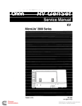
MMR-8
Modular Multitrack Recorder
MMR-8
POWER
REC
REC
REC
REC
REC
REC
REC
REC
SAFE
TRANSPORT
INPUT
INPUT
INPUT
INPUT
INPUT
INPUT
INPUT
INPUT
DESTRUCTIVE
REC TYPE
CLIP
CLIP
CLIP
CLIP
CLIP
CLIP
CLIP
CLIP
MAX
MAX
+12
DIG IN
MAX
MAX
MAX
MAX
MAX
MAX
+12
+12
+12
+12
+12
+12
+12
+6
+6
+6
+6
+6
+6
+6
+6
0
0
0
0
0
0
0
0
-6
-6
-6
-6
-6
-6
-6
-6
OMF
TONE
Pro Tools
OTHER
MIDI
TIME CODE
ERROR
-12
-12
-12
-12
-12
-12
-12
-12
-25
-25
-25
-25
-25
-25
-25
-25
SLIP
SLIP
SLIP
SLIP
SLIP
SLIP
SLIP
SLIP
REFERENCE
SAMPLE
WAVEFRAME
24-BIT REC
AES
R
WORD
MMR
RATE
BUSY
29.97
48.000
LOCK
NDF
44.100
DF
P. UP
25
P. DOWN
24
NON STD.
CAL
OFFSET
INTERLOCK
FRAME
INT
CONTROL
MODE
VIDEO
LOCAL/BUS
TC
TC CHASE
BIPH
BIPH CHASE
LYNX
BIPH TRAN
EXT RSLV
SER TRAN
SYNC GRP
1
2
3
4
EDITOR
VARI
MMR
LYNX
MAST
SLAVE
IDENT
CANCEL
1
2
CUT
COPY
SEL
SEL
3
CLEAR
SEL
4
PASTE
SEL
EVENT
EDIT
5
INSERT
SEL
6
OPEN
SEL
DELETE
MON
LOAD
TRACK
INPUT
7
UNDO
SEL
UNLOAD
VIEW
TRACK
8
REDO
SEL
BACKUP
SLIP
TRACK
CLR
TIME
CAPT
LYNX SYNC
0
IN
7
HEAD
8
OUT
TAIL
4
5
OFST
1
SHIFT
9
PREV EDIT
6
RDR
2
FREE
3
SUBF
+/-
SETUP
YES
STO
=
-
TC/FEET
+
TRIM
TRIM
JOG
SHTL
NO
RCL
LOOP
UNMOUNT
PHONES
NEXT EDIT
ON
LINE
REH
REC
LOC
MOUNT
OWNER’S MANUAL
D00000000A
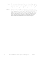
CAUTION
RISK OF ELECTRIC SHOCK
DO NOT OPEN
CAUTION: TO REDUCE THE RISK OF ELECTRIC SHOCK,
DO NOT REMOVE COVER (OR BACK). NO USERSERVICEABLE PARTS INSIDE. REFER SERVICING TO
QUALIFIED SERVICE PERSONNEL.
The lightning flash with arrowhead symbol, within an equilateral triangle, is
intended to alert the user to the presence of uninsulated “dangerous
voltage” within the product’s enclosure that may be of sufficient magnitude
to constitute a risk of electric shock to persons.
The exclamation point within an equilateral triangle is intended to alert the user
to the presence of important operating and maintenance (servicing)
instructions in the literature accompanying the appliance.
Alternating
Current
Protective
Conductor Terminal
WARNING: TO PREVENT FIRE OR SHOCK
HAZARD, DO NOT EXPOSE THIS
APPLIANCE TO RAIN OR MOISTURE.
CAUTION:
Replace battery with Panasonic or Maxell, model CR2032 only. Use of
another battery may present a risk of fire or explosion. See owner’s
manual for safety instructions
For U.S.A
TO THE USER
This equipment has been tested and found to comply
with the limits for a Class A digital device, pursuant to
Part 15 of the FCC Rules. These limits are designed
to provide reasonable protection against harmful
interference when the equipment is operated in a
commercial environment. This equipment generates,
uses, and can radiate radio frequency energy and, if
not installed and used in accordance with the
instruction manual, may cause harmful interference
to radio communications. Operation of this equipment
in a residential area is likely to cause harmful
interference in which case the user will be required to
correct the interference at his own expense.
CAUTION
Changes or modifications to this equipment not
expressly approved by TEAC CORPORATION for
compliance could void the user's authority to operate
this equipment.
IMPORTANT SAFETY INSTRUCTIONS
CONSIGNES DE SECURITE
SICHERHEITSHINWEISE
NORME DI SICUREZZA
INSTRUCCIONES DE SEGURIDAD
VEILIGHEIDSVOORSCHRIFTEN
TEAC CORPORATION
Important Safety Instructions
CAUTION:
• Read all of these Instructions.
• Save these Instructions for later use.
• Follow all Warnings and Instructions marked on the audio
equipment.
1) Read Instructions — All the safety and operating instructions
should be read before the product is operated.
2) Retain Instructions — The safety and operating instructions should
be retained for future reference.
3) Heed Warnings — All warnings on the product and in the operating
instructions should be adhered to.
4) Follow Instructions — All operating and use instructions should be
followed.
5) Cleaning — Unplug this product from the wall outlet before cleaning.
Do not use liquid cleaners or aerosol cleaners. Use a damp cloth for cleaning.
6) Attachments — Do not use attachments not recommended by the
product manufacturer as they may cause hazards.
7) Water and Moisture — Do not use this product near water _ for
example, near a bath tub, wash bowl, kitchen sink, or laundry tub; in a wet
basement; or near a swimming pool; and the like.
8) Accessories — Do not place this product on an unstable cart, stand,
tripod, bracket, or table. The product may fall, causing serious injury to a
child or adult, and serious damage to the product. Use only with a cart,
stand, tripod, bracket, or table recommended by the manufacturer, or sold
with the product. Any mounting of the product should follow the manufacturer’s instructions, and should use a mounting accessory recommended by
the manufacturer.
9) A product and cart combination should be moved with care. Quick
stops, excessive force, and uneven surfaces may cause the product and cart
combination to overturn.
10) Ventilation — Slots and openings in the cabinet are provided for
ventilation and to ensure reliable operation of the product and to protect it
from overheating, and these openings must not be blocked or covered. The
openings should never be blocked by placing the product on a bed, sofa,
rug, or other similar surface. This product should not be placed in a builtin installation such as a bookcase or rack unless proper ventilation is provided or the manufacturer’s instructions have been adhered to.
11) Power Sources — This product should be operated only from the
type of power source indicated on the marking label. If you are not sure of
the type of power supply to your home, consult your product dealer or
local power company. For products intended to operate from battery
power, or other sources, refer to the operating instructions.
12) Grounding or Polarization — This product may be equipped with
a polarized alternating-current line plug (a plug having one blade wider
than the other). This plug will fit into the power outlet only one way. This
is a safety feature. If you are unable to insert the plug fully into the outlet,
try reversing the plug. If the plug should still fail to fit, contact your electrician to replace your obsolete outlet. Do not defeat the safety purpose of
the polarized plug.
13) Power-Cord Protection — Power-supply cords should be routed
so that they are not likely to be walked on or pinched by items placed upon
or against them, paying particular attention to cords at plugs, convenience
receptacles, and the point where they exit from the product.
14) Outdoor Antenna Grounding — If an outside antenna or cable
system is connected to the product, be sure the antenna or cable system is
grounded so as to provide some protection against voltage surges and
built-up static charges. Article 810 of the National Electrical Code,
ANSI/NFPA 70, provides information with regard to proper grounding of
the mast and supporting structure, grounding of the lead-in wire to an
antenna discharge unit, size of grounding conductors, location of antennadischarge unit, connection to grounding electrodes, and requirements for
the grounding electrode.
"Note to CATV system installer:
This reminder is provided to call the CATV system installer’s attention to
Section 820-40 of the NEC which provides guidelines for proper grounding and, in particular, specifies that the cable ground shall be connected to
the grounding system of the building, as close to the point of cable entry as
practical.
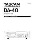
Example of Antenna Grounding as per
National Electrical Code, ANSI/NFPA 70
ANTENNA
LEAD IN
WIRE
GROUND
CLAMP
ANTENNA
DISCHARGE UNIT
(NEC SECTION 810-20)
ELECTRIC
SERVICE
EQUIPMENT
GROUNDING CONDUCTORS
(NEC SECTION 810-21)
GROUND CLAMPS
POWER SERVICE GROUNDING
ELECTRODE SYSTEM
(NEC ART 250. PART H)
NEC - NATIONAL ELECTRICAL CODE
15) Lightning — For added protection for this product during a lightning
storm, or when it is left unattended and unused for long periods of time,
unplug it from the wall outlet and disconnect the antenna or cable system.
This will prevent damage to the product due to lightning and power-line
surges.
16) Power Lines — An outside antenna system should not be located in
the vicinity of overhead power lines or other electric light or power circuits, or where it can fall into such power lines or circuits. When installing
an outside antenna system, extreme care should be taken to keep from
touching such power lines or circuits as contact with them might be fatal.
17) Overloading — Do not overload wall outlets, extension cords, or
integral convenience receptacles as this can result in risk of fire or electric
shock.
18) Object and Liquid Entry — Never push objects of any kind into
this product through openings as they may touch dangerous voltage points
or short-out parts that could result in a fire or electric shock. Never spill
liquid of any kind on the product.
19) Servicing — Do not attempt to service this product yourself as opening or removing covers may expose you to dangerous voltage or other hazards. Refer all servicing to qualified service personnel.
20) Damage Requiring Service — Unplug this product from the wall
outlet and refer servicing to qualified service personnel under the following conditions:
a) when the power-supply cord or plug is damaged.
b) if liquid has been spilled, or objects have fallen into the product.
c) if the product has been exposed to rain or water.
d) if the product does not operate normally by following the operating
instructions. Adjust only those controls that are covered by the operating
instructions as an improper adjustment of other controls may result in
damage and will often require extensive work by a qualified technician to
restore the product to its normal operation.
e) if the product has been dropped or damaged in any way.
f ) when the product exhibits a distinct change in performance _ this indicates a need for service.
21) Replacement Parts — When replacement parts are required, be
sure the service technician has used replacement parts specified by the
manufacturer or have the same characteristics as the original part.
Unauthorized substitutions may result in fire, electric shock, or other hazards.
22) Safety Check — Upon completion of any service or repairs to this
product, ask the service technician to perform safety checks to determine
that the product is in proper operating condition.
23) Wall or Ceiling Mounting — The product should be mounted to a
wall or ceiling only as recommended by the manufacturer.
24) Heat — The product should be situated away from heat sources such
as radiators, heat registers, stoves, or other products (including amplifiers)
that produce heat.
3
»
MMR-8
TEAC CORPORATION
3-7-3, Nakacho, Musashino-shi, Tokyo 180, Japan Phone: (0422) 52-5082
TEAC AMERICA, INC.
7733 Telegraph Road, Montebello, California 90640 Phone: (213) 726-0303
TEAC CANADA LTD.
5939 Wallace Street, Mississauga, Ontario L4Z 1Z8, Canada Phone: 905-890-8008 Facsimile: 905-890-9888
TEAC MEXICO, S.A. De C.V
Privada De Corina, No.18, Colonia Del Carmen Coyoacon, Mexico DF 04100 Phone: 5-658-1943
TEAC UK LIMITED
5 Marlin House, Marlins Meadow, The Croxley Centre, Watford, Herts. WD1 8YA, U.K. Phone: 01923-819699
TEAC DEUTSCHLAND GmbH
Bahnstrasse 12, 65205 Wiesbaden-Erbenheim, Germany Phone: 0611-71580
TEAC FRANCE S. A.
17 Rue Alexis-de-Tocqueville, CE 005 92182 Antony Cedex, France Phone: (01) 42.37.01.02
TEAC BELGIUM NV/SA
P.A. TEAC Nederland BV, Perkinsbaan 11a, 3439 ND Nieuwegein, Netherlands Phone: 0031-30-6048115
TEAC NEDERLAND BV
Perkinsbaan 11a, 3439 ND Nieuwegein, Netherlands Phone: 030-6030229
TEAC AUSTRALIA PTY., LTD.
A.C.N. 005 408 462
106 Bay Street, Port Melbourne, Victoria 3207, Australia Phone: (03) 9644-2442
TEAC ITALIANA S.p.A.
Via C. Cantù 5, 20092 Cinisello Balsamo, Milano, Italy Phone: 02-66010500
Tascam MMR-8 Owner’s Manual
Chapter 1 General Information ........................................................................ 9
MMR-8 Introduction ......................................................................................................................... 9
Hardware Overview ........................................................................................................................ 10
Functional Overview........................................................................................................................ 12
System Specifications....................................................................................................................... 15
Chapter 2 Installation .......................................................................................17
MMR-8 Materials Kit Box .............................................................................................................. 17
General Guidelines .......................................................................................................................... 18
Mounting Rack Ears .................................................................................................................................... 18
Installing Multiple MMR Units .................................................................................................................... 19
AC Mains and Grounding Considerations..................................................................................................... 20
Audio Cables.................................................................................................................................... 20
MMR-8 Back Panel Connections .................................................................................................... 21
Audio Connections ...................................................................................................................................... 22
Analog In/Out Connections...................................................................................................................... 22
Digital In/Out Connections ...................................................................................................................... 22
Monitoring Connections........................................................................................................................... 22
Timecode and Video Reference Signals........................................................................................................ 23
Video In/Out............................................................................................................................................ 23
SMPTE/EBU Time Code In/Out .............................................................................................................. 23
VITC In................................................................................................................................................... 23
Biphase Connections................................................................................................................................ 24
Digital Audio Sample Reference Connections .............................................................................................. 24
Word Clock ............................................................................................................................................. 24
AES/EBU Sample Rate............................................................................................................................ 24
MIDI Connections ....................................................................................................................................... 25
External Controllers & Bus Connections ...................................................................................................... 25
Lynx Bus / KCU Connection ................................................................................................................... 25
MMR Sync Bus Connections ................................................................................................................... 25
Serial Transport Connection..................................................................................................................... 26
Serial Editor Connection .......................................................................................................................... 26
Parallel Transport .................................................................................................................................... 26
Parallel Tracks......................................................................................................................................... 26
Connecting External SCSI Media ................................................................................................... 26
Remote Controllers for the Tascam MMR-8 .................................................................................. 27
Powering Up the System.................................................................................................................. 28
Verifying MMR-8 Installation......................................................................................................... 28
Software Updates......................................................................................................................................... 29
Factory Default Settings .................................................................................................................. 30
Testing Your Installation................................................................................................................. 30
MMR-8
Tascam MMR-8 Owner’s Manual • Table of Contents
5
Chapter 3 MMR-8 Operation...........................................................................33
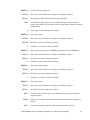
MMR-8 Keys & Definitions .............................................................................................................33
MMR-8 Front Panel.........................................................................................................................35
Front Panel Indicators, Switches, and Displays ..............................................................................37
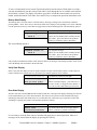
LED Indicators ............................................................................................................................................ 37
Configuration Settings............................................................................................................................. 37
Active Mode/Key Indicators .................................................................................................................... 37
Track Status and Metering ....................................................................................................................... 37
Meter LEDs ............................................................................................................................................ 37
Machine Status LEDs .............................................................................................................................. 38
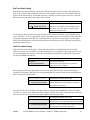
Liquid Crystal Display (LCD)...................................................................................................................... 39
Normal State Display............................................................................................................................... 39
Setup State Display.................................................................................................................................. 40
View Track State Display ........................................................................................................................ 40
Slip Track State Display .......................................................................................................................... 41
Load Track State Display......................................................................................................................... 41
Backup State Display............................................................................................................................... 42
Verify State Display ................................................................................................................................ 42
Error State Display .................................................................................................................................. 42
Front Panel Key Groups ..................................................................................................................43
Transport Group .......................................................................................................................................... 43
Setup and Wheel Group ............................................................................................................................... 44
Wheel.......................................................................................................................................................... 46
Track Group ................................................................................................................................................ 46
Keypad Group ............................................................................................................................................. 55
Basic Operation................................................................................................................................61
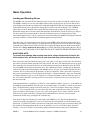
Loading and Mounting Drives...................................................................................................................... 61
Loading a Project, Session, or Composition ................................................................................................. 62
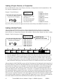
Loading Individual Tracks ........................................................................................................................... 62
Viewing Tracks ........................................................................................................................................... 63
Unloading Tracks ........................................................................................................................................ 63
Deleting Tracks from the Disk ..................................................................................................................... 63
Recording a New Project .................................................................................................................63
Using Registers .................................................................................................................................64
Recalling Registers...................................................................................................................................... 64
Capturing the Current Time Code ................................................................................................................ 64
Trimming Time Code Values....................................................................................................................... 65
Using the Entry Register.............................................................................................................................. 65
Local & Studio Monitoring..............................................................................................................66
Headphone Volume (LEVEL)...................................................................................................................... 66
Headphone Jack (PHONES) ........................................................................................................................ 66
Chapter 4 MMR-8 Setup Menus......................................................................67
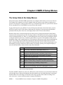
The Setup State & the Setup Menus ................................................................................................67
Setup Operation ...............................................................................................................................68
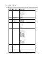
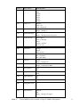
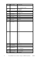
Setup Menu Chart............................................................................................................................69
6
Tascam MMR-8 Owner’s Manual • Table of Contents
MMR-8
Setup Menu Details.......................................................................................................................... 73
Control Mode............................................................................................................................................... 73
Local/Bus ................................................................................................................................................ 73
Time Code Chase..................................................................................................................................... 73
Biphase Chase ......................................................................................................................................... 73
Biphase Transport.................................................................................................................................... 73
Serial Transport ....................................................................................................................................... 74
Editor ...................................................................................................................................................... 74
Varispeed ................................................................................................................................................ 74
User Settings................................................................................................................................................ 74
The Lynx Bus .............................................................................................................................................. 75
Transport Control .................................................................................................................................... 75
Track Record Arm/Select......................................................................................................................... 75
Head/Tail ................................................................................................................................................ 75
Slip Track/Region.................................................................................................................................... 75
Prev/Next ................................................................................................................................................ 76
Undo/Redo .............................................................................................................................................. 76
Clear/Paste .............................................................................................................................................. 76
Record Mode ............................................................................................................................................... 77
Non-Destructive....................................................................................................................................... 77
Auto Cleanup .......................................................................................................................................... 77
Tape Mode .............................................................................................................................................. 77
The MMR Bus ............................................................................................................................................. 78
Chapter 5 MMR-8 System Applications..........................................................79
Film Post Production ....................................................................................................................... 79
The MMR-8 As Master................................................................................................................................ 80
Biphase Setup Menus................................................................................................................................... 80
MMR-8 Film Connections ........................................................................................................................... 82
Video Post Production ..................................................................................................................... 82
The Lynx Bus .............................................................................................................................................. 82
Chapter 6 Maintenance & Service ...................................................................83
System Input Level Calibration Using the Meter LEDs................................................................. 83
MMR Input and Output Level Calibrations................................................................................................... 83
MOC Calibration Procedure ......................................................................................................................... 84
MIC Calibration Procedure .......................................................................................................................... 85
Adding External Drives to the System ............................................................................................ 86
Formatting Disks ............................................................................................................................. 86
Using Removable Media.................................................................................................................. 86
Chapter 7 Technical Support ...........................................................................87
MMR-8 System Software ................................................................................................................ 87
Appendix A: Control Panel Command Summary.......................................................................... 89
Transport Group ...................................................................................................................................... 89
Setup and Wheel Group ........................................................................................................................... 89
Keypad keys ............................................................................................................................................ 90
Track Select Keys .................................................................................................................................... 92
Appendix B: TASCAM MMR-8 Drive Compatibility Chart ......................................................... 93
Appendix C: WaveFrame Compatibility ........................................................................................ 95
MMR-8
Tascam MMR-8 Owner’s Manual • Table of Contents
7
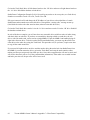
Appendix D: MMR-8 Cable Information ........................................................................................97
PARALLEL TRACKS and PARALLEL TRANSPORT Connector.............................................................. 97
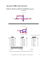
MIDI IN/THRU/OUT Connector pinout ...................................................................................................... 98
LYNX (Remote Controller) Connector pinout.............................................................................................. 98
EDITOR Connector pinout .......................................................................................................................... 98
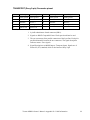
TRANSPORT (Sony 9-pin) Connector pinout.............................................................................................. 99
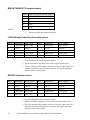
ANALOG INPUT & OUTPUT Connectors pinouts ....................................................................................100
BIPH (Biphase) Connectors pinout .............................................................................................................100
DIO (AES/EBU Digital Audio) Connector pinout .......................................................................................101
SYNC (MMR-Bus) Connector pinout .........................................................................................................101
TIMECODE IN Connector .........................................................................................................................102
TIMECODE OUT Connector .....................................................................................................................102
WORD CLOCK IN Connector ...................................................................................................................102
WORD CLOCK OUT Connector................................................................................................................102
VIDEO IN/OUT Connector ........................................................................................................................102
VITC IN Connector ....................................................................................................................................103
SERIAL CONNECTORS ...........................................................................................................................103
SCSI Connector..........................................................................................................................................103
PRX Connector ..........................................................................................................................................103
Appendix E: MMR-8 Glossary ......................................................................................................105
Index ...............................................................................................................................................111
MMR-8 Owner’s Manual Version 1.20CE
8
Tascam MMR-8 Owner’s Manual • Table of Contents
MMR-8
Chapter 1 General Information
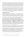
This chapter presents the main features and capabilities of the MMR-8 hardware and a functional
overview of its Panel/Display states. MMR-8 product specifications are also included.
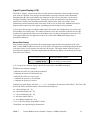
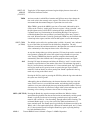
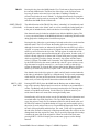
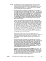
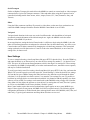
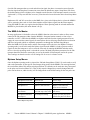
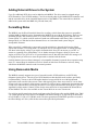
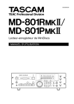
MMR-8 Introduction
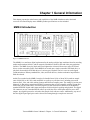
Figure 1-1. MMR-8 Front View
The MMR-8 is a non-linear digital replacement for the analog or digital tape machines found in recording
studios and broadcast facilities, and for magnetic film dubbers found in film and video post-production
facilities. The MMR-8 can play back and record eight tracks of material from one or more SCSI hard
drives or other removable media. Each MMR-8 can record onto a single removable SCSI hard drive, or
play back from multiple SCSI disk drives of various types. Playback can be in exact or track-slipped
synchronization to industry-standard film, video, and audio devices, whether mechanical tape-based or
hard drive-based.
Audio files recorded on the MMR-8 consist of selectable linear 16-bit or linear 24-bit words at sample
rates of 48.0 kHz or 44.1 kHz, each modifiable to a pull-up or pull-down level, including conversion
between PAL, film, and video, making fourteen total discrete sampling rates. The analog I/O section uses
balanced +4 dBu analog connections on DB-25 connectors that are pin-compatible with the Tascam DA88 and may use the same cables. The DIO (Digital I/O) card allows direct connection of the MMR to
standard AES/EBU digital audio inputs and outputs for direct digital recording and playback. The digital
I/O connector can use a standard DA-88 cable to provide four stereo AES inputs and four stereo AES
outputs. Any digital input can be selected as the sample clock reference source. Additionally, any one of
the four digital input signal pairs can be selected for routing through a sample rate converter.
Tascam MMR-8 Owner’s Manual • Chapter 1 • General Information
MMR-8
9
The MMR-8 will directly play back material created on Digidesign Pro Tools or WaveFrame digital
audio workstations, as well as OMF Compositions which reference Sound Designer II audio media files.
The disk drive or drives containing edited Session, Project, or OMF files are simply “unplugged” from
the workstation and then “hot-plugged” into the MMR-8, using the standard internal Kingston hard drive
carrier, or otherwise connected to the MMR-8’s external SCSI port. Once the drive(s) are mounted by the
MMR-8, tracks from one or more projects may be loaded as required for the mix session. Sound files of
the same or different audio formats may thus be played back simultaneously from one or more drives.
When the MMR-8 is turned on for the first time, the system default operating parameters are installed,
and the machine is placed into the Normal state (see the Functional Overview below). Users can also save
up to ten settings files that have MMR-8 parameters “customized” or set for a particular application.
These settings files are stored on the internal hard drive so that they can be used to instantly reconfigure
the MMR-8 between mix sessions. The MMR-8’s operating parameters can be manually changed before
or even during a mix session, through menu selections. Optional password protection may be used to
prevent some parameters from being changed inadvertently.
Hardware Overview
The MMR-8 comes standard with one removable Kingston drive carrier. The Kingston carrier can hold a
standard SCSI drive for recording and playback of audio tracks. An internal IDE hard drive holds the
operating system, the MMR-8 software, and the parameter settings files. Additional external SCSI drives
can be connected and (after power-up) accessed by the MMR-8. This eliminates having to pre-combine
tracks from multiple drives onto a single drive. A list of approved media drives is given in Appendix B.
The MMR-8 is based on a standard Intel Pentium™ processor-based PC motherboard, with integral PCI
and ISA bus slots running under an industry-standard operating system. The MMR-8 DSP,
synchronization, and audio interface boards plug directly into this PC motherboard. There is a Lithium
battery #CR2032 for the CMOS circuit on the motherboard. Caution: Battery May Explode if
Mistreated. Do Not Recharge, Disassemble or Dispose of in Fire. The MIC (MMR-8 analog-to-digital
Input Converter) and MOC (MMR-8 digital-to-analog Output Converter) boards are in their own shielded
cage, connected to the AIO (Analog I/O) card via ribbon cables. The PRX (DSP) card performs the audio
processing for the MMR-8. A standard Symbios SCSI-2 controller card also plugs into the PCI bus. The
Sync card, the UI/B (User Interface/Biphase) card, the AIO (analog I/O) card, and the DIO (AES/EBU
digital I/O) card are all plugged into the ISA bus. The Biphase Operations Board (BOB) occupies a slot
on the back panel to provide connections for the system’s four Biphase inputs and one Biphase output. It
is attached to the UI/B card via a ribbon cable and is not plugged into a slot.
Very high quality 20-bit converters on all analog inputs and outputs assure excellent audio fidelity. The
MMR-8 uses 24-bit internal digital resolution for all digital audio processing. Recorded audio is stored in
standard linear 16-bit or 24-bit sound files. The MMR-8 can read StudioFrame or WaveFrame sound files
as well as Sound Designer II files, AIFC files, and .WAV files, all in either 16 or 24-bit resolution.
The MMR-8 front panel contains 45 soft-touch keys with most of the common dubber and audio playback
functions available through one or two keystrokes. There are also seven large illuminated motion control
buttons (Play, Stop, FF, Rew, Reverse Play, Record, Rehearse) for track playback and “play head”
locating, and an Online button for setting the MMR-8 offline (as a local machine) or online (as a
synchronized slave or a master machine). When the MMR-8 is the master and is online, then any number
of external SMPTE/EBU, MTC or biphase devices will follow the MMR-8. When the MMR-8 is set as a
slave, it can chase time code, biphase, a TimeLine Lynx™ module, or another MMR-8.
10 MMR-8
Tascam MMR-8 Owner’s Manual • Chapter 1 • General Information
A 40-character (two line by 20-character) LCD (Liquid Crystal Display) serves as the MMR-8 status and
control text window. The top line typically shows the machine status and current time code or feet/frames
location, while the bottom line shows various time code registers (memory, slip. etc.) and accepts input
from the front panel. The entire display may also alert the operator to any machine or user error
conditions. It can be scrolled horizontally or vertically, using the Wheel or arrow keys, for entering
Panel/Display state and setup information, or for finding and loading tracks.
As with other 8-track recorders, there are dedicated front panel LED peak meters that always display
monitor level information for the track outputs whether in audio input or playback. Each meter contains
seven green, yellow and red LEDs plus a CLIP/Hold LED for easy at-a-glance level monitoring. An
additional 74 status LEDs instantly identify current synchronization modes, bus control modes, sample
and frame reference settings, record format settings, transport status, and front panel input status.
The MMR-8 rear panel contains all the audio and synchronization connections. To minimize connector
footprint, female DB-25 connectors are used for the audio connections. The eight analog audio inputs are
on one female DB-25 and the eight analog audio outputs are on another female DB-25. Each analog
connector mounts on a separate card within the chassis, and is labeled Input or Output. The connectors are
pin-compatible with the Tascam DA-88 analog audio connector.
The DIO card allows direct digital audio transfers into and out of the MMR-8. Because it uses standard
AES/EBU digital signal conventions, there are four stereo digital inputs and four stereo digital outputs
with odd-even track pairs. Tracks 1+2 are on the first AES/EBU connection, tracks 3+4 on the second
AES/EBU connection, and so on. All eight tracks (four pairs of in and out) are on a single female DB-25
connector. Any of the digital inputs can serve as a sample rate reference and any of the input pairs can
also be routed through an on-board sample rate converter. Note that this connector carries AES/EBU
digital signals and is NOT pin-compatible with the Tascam DA-88 TDIF digital audio format connector.
Built-in biphase control allows the MMR-8 to automatically lock to and chase biphase devices
without having to use an external biphase to SMPTE/EBU adapter. Up to four biphase input
signals can be simultaneously connected to the MMR-8. The active biphase input is determined by menu
selection. A biphase output allows the MMR-8 to directly control a single biphase bus. Software setup
parameters allow various biphase device limitations to be imposed upon the MMR-8 (speed of fast
forward and rewind, ramp up and stop speed, etc.). Not intended for public telecommunications
network connection.
Video post-production work can be done with any industry-standard playback device. The MMR-8
supports VITC, SMPTE/EBU LTC time code, Word Clock, house sync, MTC, and P2-bus (Sony 9-pin)
protocols.
The Tascam MM-RC is a dedicated remote control unit designed specially for use with the MMR-8 and
the MMP-16 sixteen-channel player unit. It connects directly to the UI/B board on the MMR back panel
and allows control of any combination of up to 100 MMR-8 or MMP-16 units.
The TimeLine Lynx Keyboard Control Unit (KCU) can function as a remote controller for up to six
MMR-8s or other transports as the MMR-8 contains an integrated Lynx-2 synchronizer. The Lynx KCU
900 software includes special MMR support for some editing and event slip commands. Other remote
controllers can also be used for controlling the transport and track arm functions of the MMR-8 through
the two Parallel Remote ports or the Editor Remote port.
Tascam MMR-8 Owner’s Manual • Chapter 1 • General Information
MMR-8
11
Functional Overview
The MMR-8 operates in any of eight different Panel/Display states (simply referred to as “states” for
convenience). These states are distinguished by the nature of the information displayed in the LCD
window and by which keys are functionally available while in that state. These MMR-8 Panel/Display
states are described here.
Normal state is the default Panel/Display state on power-up. In this state, the LCD shows the current
system play time in the top of the display, and shows the active register (last requested register or function
time) in the bottom of the display. All keys are active while in this state, and will respond by performing
an action, accessing a register, or changing to the state written on the key. Shifted key functions are also
available by first pressing the SHIFT key, then pressing the key which corresponds to the desired shifted
function. Once the SHIFT key is selected, pressing the appropriate key to activate the desired shifted
function completes the SHIFT operation. The SHIFT state can be cancelled by pressing SHIFT again, or
by pressing CLR, to return the system to normal key selection.
Pressing the SETUP key activates the Setup state. This state gives access to the system setup menus,
where most of the operating parameters of the MMR-8 can be altered. Some parameters are changeable
only under certain operating conditions (non-record, stopped, etc.), although all are viewable at any time
in the Setup state. Once in the Setup state, you may return to the Normal state by pressing the SETUP key
again, or by pressing CLR.
There are three types of Panel/Display states that deal with MMR-8 track operations. These are Load
Track, View Track, and Slip Track. Pressing the LOAD TRACK, TRACK, or SLIP keys puts the
MMR-8 into one of these Track states. The SEL keys for each MMR track are used in conjunction with
these keys to identify the specific track to be loaded, viewed, or slipped.
There are also three keys to the left of the Track state keys labeled EDIT, MON, and INPUT. These keys
do not change the state of the MMR display, but are used to determine what status is being indicated for
each MMR track by the track selection LEDs when the SEL keys are pressed while in the Normal state of
operation. One of these keys is always active as the current Track Mode. Since these keys function along
with the Track state keys to identify the function being specified by the SEL keys, the entire group of six
keys (EDIT, MON, INPUT, LOAD TRACK, TRACK, and SLIP) are also referred to as the Track Mode
keys.
The Track states supersede the Normal state since they change the display and make certain keys
unavailable until the Track state is exited or cleared. To exit a Track state and return the MMR-8 to the
Normal state, it is necessary to either complete the selected track operation (by pressing STO to load a
Project, for example), or press the selected Track state key again, or press the CLR key to cancel the
operation. After exiting a Track state, the system will return to the Normal state and the last selected
Track Mode (EDIT, MON, INPUT).
Pressing the LOAD TRACK key activates the Load Track state. This state allows for loading
WaveFrame projects, OMF Compositions, or Pro Tools Session files from any mounted disk volume.
This state also allows loading of individual tracks from a Project, Composition, or Session (hence the
name of this key and state), and moving of tracks from one MMR channel to another. The shifted function
of LOAD TRACK allows for deleting WaveFrame Projects or Tracks. The MMR-8 software does not
currently allow OMF Compositions and Pro Tools Session Files to be deleted.
12 MMR-8
Tascam MMR-8 Owner’s Manual • Chapter 1 • General Information
The MMR Backup state is accessed via the Load Track state by pressing SHIFT+SLIP after choosing
(scrolling to) the desired Project while in the LOAD TRACK state. This state is similar to the Setup state
in that it has two menu choices which are accessed by using the Up/Down arrow keys or the Wheel. The
key choices available in the Backup state are the same as those in the Setup state, hence it exists at the
same level of the hierarchy of panel/display states as the Setup state.
Pressing the TRACK key activates the View Track state. This state allows for viewing the names of
loaded tracks, and unloading of tracks (the shifted function of the TRACK key) from the loaded track list.
Pressing the SLIP key activates the Slip Track state. This state allows for slipping one or more of the
already loaded tracks in time.
Verify state supersedes the Normal and Track states. The two most common Verify state functions are
confirmation (a Yes/No answer is required from the user) and password entry (a password must be
entered to complete the action request). Both of these requests override most other actions or do not allow
access to the Normal, Setup, or Track states until they are cleared or a valid response is entered. Verify
state, when cleared, usually drops the MMR-8 back into the previously active state.
Error state is the final level in the hierarchy of Panel/Display states. In this state, the ERROR status light
flashes and the user is asked to clear a condition by pressing the CLR key, or if that is impossible (as in
the case of a fatal error), to note the error information and possibly take some extraordinary action (such
as re-starting the MMR-8). Until the Error state is cleared, or a valid response is entered, access to the
Normal, Setup, or Track states is not allowed. The Error state, when cleared, may drop to another state, or
to any appropriate condition—depending on the type and severity of the error.
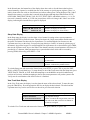
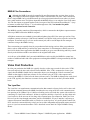
These states are hierarchical in the sense that some require a response or they require a state to be cleared
before certain keys or other states can be accessed. The Normal state is at the base of the hierarchy
because it is the default on startup and can always be accessed from any other state or by pressing the
CLR key as many times as is necessary to clear any other state. The track record arm function and the
transport keys can be accessed directly from any state, so the MMR can always record and playback,
regardless of what other functions or states are being accessed. The following diagram illustrates the
hierarchical relationship between the various states, based on the number of choices available from each
state.
Tascam MMR-8 Owner’s Manual • Chapter 1 • General Information
MMR-8
13
EErrrroorr
V
Veerriiffyy
LLooaadd,, V
Viieew
w,, SSlliipp TTrraacckk
SSeettuupp,, B
Baacckkuupp
N
Noorrm
maall
Figure 1-3. MMR-8 Panel/Display State Hierarchy
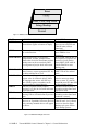
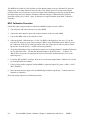
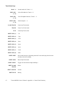
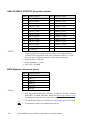
STATE
NORMAL
LCD WINDOW DISPLAY
Shows current play head time on top and
selected time register on bottom of display.
SETUP
LOAD TRACK
VIEW TRACK
SLIP TRACK
VERIFY
ERROR
BACKUP
COMMENT
Default at startup. Allows
direct access to SETUP and
TRACK states, all keys
functional.
Shows setup menus and parameter choices
Press SETUP to enter state,
for each menu item.
press TRIM to view
parameters.
Shows disk directory list of projects,
Press LOAD TRACK once to
compositions, sessions, and their tracks.
see Project level, again to see
Shows other levels for WaveFrame projects. successive levels (tracks).
Backup state can be accessed only while
Press SHIFT+SLIP while in
viewing name of project while in this state.
LOAD TRACK to enter
Backup state.
Shows the name of each loaded track. Use
Press TRACK to enter state,
wheel, arrows, or press appropriate SEL key SHIFT+TRACK to unload
to choose which track to view.
track.
Shows Current Play position on top, Slip
Press SLIP to enter state, use
register value for each track below, allows
wheel or arrows to change
for slipping tracks in time. All SEL keys
value, or enter TC value on
have a SLIP register, so numbers can be
keypad & press STO then SEL
stored, recalled, or cleared directly.
to enter number directly.
Asks for a response (usually requires
Disallows most key entry or
pressing Yes or No) to clear state and return switching to other states until
to previous state.
response is made.
Shows Error message, usually requires
Disallows most key entry or
pressing CLR to clear and return to previous switching to other states until
state.
condition is cleared.
Menu with two choices: BeginBackup to
Accessed only via LOAD
(device#) or TapeMode Convert to (device#). TRACK state. Use Up/Down
Only currently mounted devices will appear arrows or wheel to choose
Backup style, press STO to
as choices.
begin backup process.
Figure 1-4. MMR-8 Panel/Display State Chart
14 MMR-8
Tascam MMR-8 Owner’s Manual • Chapter 1 • General Information
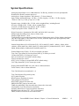
System Specifications
Analog Input and Output Level:+4 dBu balanced, +24 dBu clip, nominal levels trim pot adjustable
Headroom:20 dB above nominal input level
Analog Input / Output Impedance: 10k, balanced / <75 ohms, balanced
Input / Output Adjustment Range: +10 dBu - +25 dBu, clipping / +18 dBu - +25 dBu, clipping
THD+N:<.004 % @ 1 kHz, @ clip level -0.5 dB
Dynamic range:>104 dB (10 Hz - 22 kHz, with A-weighted filter), including Record.
S/N ratio:>108 dB (10 Hz - 22 kHz, with A-weighted filter)
Crosstalk:<-85 dB (between any channels, 20 Hz - 20 kHz)
Frequency Response:20 Hz - 20 kHz ±0.1 dB
Digital Conversion / Quantization:20-bit ADC and 20-bit DAC conversion
Sample length, Recording:16-bit, linear or 24-bit, linear
Sample Length, Internal: 24 bit
Timing Reference sources:Internal, Internal Varispeed, Follow time code in, Follow biphase signal input
(any one of four inputs), Video (either NTSC or PAL), AES/EBU digital clock input (optional), Word
clock input, MMR bus, Lynx bus
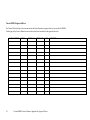
Internal Sample Rates in Hz: 42294 (44x23/25), 42336 (44x24/25), 44056 (44100-), 44100, 44144
(44100+), 45938 (44x25/24), 45983 (44x25/23), 46034 (48x23/25), 46080 (48x24/25), 47952 (48000-),
48000, 48048, (48000+),50000 (48x25/24)50050 (48x25/23)
External Sample rates:32 kHz - 51 kHz (via external sync input)
Time Code Type & Rate:30 Non drop frame (NDF) @ 30 frames per second
30 Drop frame (DF) @ 30 frames per second
PAL @ 25 frames per second (PAL default setting)
Film @ 24 frames per second
NTSC @ 29.97 frames per second NDF (NTSC default setting)
29.97 Drop frame(DF) @ 29.97 frames per second
Display Modes:SMPTE/EBU time code, with or without subframes
Feet & Frames, with or without subframes
Time Code Memories:ten (numbered 0 - 9)
Time Code Registers:IN (punch in point)
OUT (punch out point)
HEAD (jump to beginning of project)
TAIL (jump to end of project)
NEXT EDIT (jump to next track edit)
PREVIOUS EDIT (jump to last track edit)
TIME (for establishing 0 film feet and frames referenced to time code)
LYNX SYNC (Lynx bus offset time calculation)
OFFSET (Offset time for Lynx bus and time code chase)
READER (time code from LTC, VITC or Serial inputs)
FREE (available record time on current disk) lskdf
Tascam MMR-8 Owner’s Manual • Chapter 1 • General Information
MMR-8
15
Electrical Ratings:
115 VAC @ 2A, 50-60Hz 230 W Max
-OR230 VAC @ 1A, 50-60Hz 230 W Max
Nominal temperature should be 41 to 95 degrees Fahrenheit (5 to 35 degrees Centigrade).
Relative humidity should be 30 to 90% (non-condensing)
Analog input/output is 12.28 VRMS Max
Weight is approximately 37 Pounds ( 16.78 Kilograms) with a hard disk loaded.
16 MMR-8
Tascam MMR-8 Owner’s Manual • Chapter 1 • General Information
Chapter 2 Installation
This chapter covers the physical installation of the Tascam MMR-8 as either a stand-alone
recording/playback system or as part of a larger, multiple unit digital dubber system. Descriptions are
given of the various connectors on the MMR back panel. Both general installation procedures and specific
application installations are covered.
MMR-8 Materials Kit Box
Before connecting the MMR-8 hardware to your audio system and to your video or film playback
devices, verify that you have all the equipment required to complete the task. The following equipment is
included in the MMR Materials Kit Box:
Rack Ears Kit
For rack mount installation, the two rack ears may be attached to the front sides of
the MMR-8 chassis using the six 8-32 x 3/8” Phillips head screws included in the
MMR-8 materials kit. The MMR-8 can be used without the rack ears for desktop
applications.
MMR Bus
Sync Cable
A three-foot sync cable for synchronizing the operation of multiple MMR
8’s together via the rear panel MMR bus connectors.
RS422 Cable
A 9-pin RS-422 (232) cable for attaching the COM port to a terminal for running
field diagnostics. Also may be used for 9-pin serial connections.
Kingston
Removable
SCSI Drive
Carrier Instructions
One Kingston removable drive carrier is included with the system. This
carrier allows drives to be hot-swapped while the system is powered on. It
is necessary to install a SCSI drive from the list of approved drives into the
Kingston carrier before you can record or playback audio using the carrier with the
MMR-8. The instruction manual for installing drives in the Kingston carrier is in
the MMR-8 materials kit.
AC Power Cord
Toolkit
MMR-8
A six-foot (1.83 Meter) IEC AC Mains cordset is included with the MMR-8. The
mains connector for 115 VAC systems is USA standard. A six-foot (1.83 Meter)
AC Mains cordset for use in Europe, proper for the country of use will be supplied
by your TASCAM dealer. Attach the AC connector in accordance with local
requirements.
As a convenience, a small toolkit consisting of a “tweaker” and a small screwdriver
is included in the zip-locked plastic bag in the materials kit. The “tweaker” may be
used for making any necessary adjustments to the analog trim pots on the analog
audio output board.
Tascam MMR-8 Owner’s Manual • Chapter 2 • Installation
17
General Guidelines
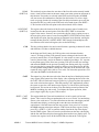
Mounting Rack Ears
The MMR-8 is a self-contained eight channel digital playback and recording device designed to be
mounted in a standard 19” (48.26 cm) IEC equipment rack in either the mix studio or a dedicated machine
room in a professional audio recording facility. As such, each MMR-8 is housed in a steel chassis 19inches (48.26 cm) wide by 17 ¼ inches (43.81 cm) deep by 7-inches (17.78 cm) tall. Each MMR-8
requires 5U (7-inches or 17.78 cm) of rack space.
Integral rack ears are provided with the chassis. If the unit is not rack-mounted, the rack ears do not need
to be installed onto the MMR-8 chassis. For rack mounting, install one rack ear to the front of each side of
the MMR-8 (three Phillips screws per side are supplied for fastening the rack ears to the chassis).
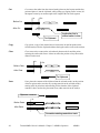
Figure 2-1. Rack Ear Installation
18
Tascam MMR-8 User’s Guide • Chapter 2 • Installation
MMR-8
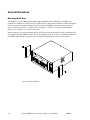
Installing Multiple MMR Units
Multiple units can be mounted one on top of the other when forced air rack ventilation is provided. A oneinch clearance is required on both sides of the MMR-8. In facilities with raised computer room-style
flooring, a ventilation opening in the floor is recommended. In no case should the internal rack
temperature ever exceed 110 degrees Fahrenheit (43 degrees Centigrade) during normal operation (as
measured at the rear of any of the MMR-8s in the system).
Figure 2-2. Multiple MMR-8 Rack Installation
MMR-8
Tascam MMR-8 Owner’s Manual • Chapter 2 • Installation
19
AC Mains and Grounding (Earthing) Considerations
Each MMR-8 requires one AC mains connection. A standard six-foot (1.83 Meter) power cordset is
included with each MMR-8, wired for the USA standard. A six-foot (1.83 Meter) AC Mains cordset for
use in Europe, proper for the country of use will be supplied by your TASCAM dealer. The AC mains
outlet must be capable of delivering 230 watts (2 amps) for each MMR-8 in the system. The main power
supply has a 115/230 VAC switch on the back of the unit. This switch should be set to match the facility
power level.
An unswitched female IEC convenience outlet is located on the rear panel of each MMR-8. In normal use
there is no connection to this outlet, although other electronics equipment using IEC plugs, and drawing
less than 120 watts total, can be connected to this outlet using the appropriate male-to-female IEC power
cord (like those used with computer monitors).
A facility-wide UPS system is recommended for protecting the MMR-8, and all your audio equipment,
from power line spikes, surges, brownouts, and line failure. If a facility-wide UPS is not available, each
MMR-8 should be connected to a home computer-type surge/spike protection system (of 250 watts
minimum) which is then plugged into an isolated ground AC outlet.
Caution: Grounding (Earthing)
Do not defeat the AC cord U-ground as this will present a potentially dangerous operator
hazard. Using an isolated ground outlet ensures the proper chassis grounding to the
mains “power company” ground. Using only isolated ground outlets throughout a facility
will prevent audio ground loops caused by AC outlets with different ground potentials. A
Ground Stud is provided on the back panel for chassis grounding of the MMR-8.
Audio Cables
Analog I/O Cables All analog input and output on the MMR-8 is done through a pair of 25-pin
D-sub connectors which are pin-compatible with the Tascam DA-88 connector.
Tascam DA-88 DB-25 to XLR cables, with either male (output) or female (input)
XLR connectors, are available from your authorized Tascam dealer.
Digital I/O Cables Analog I/O cables can be adapted for use as Digital I/O cables using 4 XLR gender
adapters. This arrangement provides four stereo AES/EBU digital inputs and four
stereo AES/EBU digital outputs using a standard DA-88 cable.
20
Tascam MMR-8 User’s Guide • Chapter 2 • Installation
MMR-8
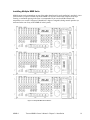
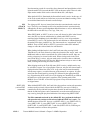
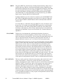
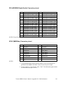
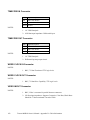
Figure 2-3. MMR-8 Back Panel
MMR-8 Back Panel Connections
The MMR back panel has connectors for the system analog and digital audio input/output, as well as
various types of synchronization and control signals. The following MMR back panel connections are
described in this chapter, and the pin outs for many of these connectors are given in Appendix D: Cable
Information.
•
•
•
•
•
•
•
•
•
•
•
•
•
•
•
•
•
•
•
•
•
•
Analog audio in
Analog audio out
Digital audio I/O
• Biphase in (BOB)
Not intended for public telecommunication network connection
• Biphase out (BOB)
Mono mix audio out (PRX)
SCSI
Remote control (UI/B)
MMR bus (Sync)
Word clock in
Word clock out
Video in
Video out
Midi in
Midi out
Midi thru
VITC in
Time code in
Time code out
Lynx (2 connections)
Editor (Sony 9-pin)
Transport (Sony 9-pin)
Parallel Tracks
Parallel Transport
MMR-8
Tascam MMR-8 Owner’s Manual • Chapter 2 • Installation
21
Audio Connections
All audio inputs and outputs (both analog and digital) connect to/from the MMR-8 using DB-25
connectors. The pin configuration used on the DB-25 analog audio connectors is identical to that used for
Tascam DTRS format digital tape machines such as the DA-88. Two female DB-25 connectors are used
for the analog connections, one for input and one for output, as labeled on the MMR back panel. A single
female DB-25 carries all eight channels of AES/EBU digital input and output signals.
Analog In/Out Connections
All analog inputs and outputs use balanced signals designed to mate with standard 600-ohm devices using
+4 dBu levels. Internal trim pots are available to set the exact input levels, as required to match external
equipment, although the MMR-8 is factory set to a nominal +4 dBu in and out. The inputs can also be set
for a nominal -10 dBu level for unbalanced consumer and semi-pro equipment signal levels.
Analog audio processing is done on two separate 20-bit Analog to Digital and Digital to Analog converter
cards mounted within the MMR-8. These converters are mounted in a special shielded cage within the
MMR and are attached via ribbon cable to a card (labeled A I/O) plugged into one of the system ISA bus
slots on the PC motherboard. These A/D and D/A boards have their own power supply separate from the
main PC power supply. Maximum load is 12.28 vrms.
Digital In/Out Connections
A single female DB-25 connector is used to provide four stereo digital inputs and four stereo digital
outputs. Tascam DA-88 analog I/O cables can be adapted for use as Digital I/O cables by using 4 XLR
gender adapters. Digital input 1 is the default reference track for the AES/EBU reference. This can be
changed to use digital input 3, 5, or 7 from one of the other three digital input pairs using Setup Menu 600
(Dig In Ref Track).
NOTE: The digital clock signals coming from any external device connected to the AES/EBU inputs will
force the MMR-8’s internal clock to try to lock to it when digital input is selected (Setup Menu 500). This
can cause playback and record problems if the clock source is not accurate. If this occurs set that track to
use the sample rate converter in Setup Menu 500 (Input Source).
Monitoring Connections
For monitoring at the MMR-8 there is a mono headphone jack on the front panel (compatible with stereo
headphones of either low or high impedance). For studio Cue or remote monitoring there is a rear panel
line level mono mini phone jack. It is an unbalanced output designed to be connected to external
amplification.
The front panel headphone monitor jack is controlled by the LEVEL control located next to the jack on
the front panel. Press the MON key and select the desired tracks using the Track Select keys to choose
which of the MMR-8 tracks will be summed to appear at the headphone jack output. The rear panel jack
is a pre-LEVEL control, so it is a fixed line level output (-10 dBu), and it always presents a summed
output of the audio channels selected using the MON function on the front panel.
22
Tascam MMR-8 User’s Guide • Chapter 2 • Installation
MMR-8
Timecode and Video Reference Signals
To accurately synchronize the MMR-8 to film or video, or with other audio playback equipment, some
method of providing a stable timing reference must be used. Because the MMR-8 is very flexible, there
are numerous methods one could use to connect film and video equipment. The best method depends
upon the chosen method of sync, the other equipment that is being controlled, and whether the MMR-8
will be the master or a slave to the other equipment. This section covers the various reference signals
available on the MMR-8 system and their applications.
Video In/Out
Most video post houses have a common house sync signal to lock all the audio and video equipment in
the facility to a standard video reference signal. This insures that all devices receiving the house sync
signal will lock together to the edge of the video frame. The house sync signal can be black burst,
composite sync, or color bars in NTSC or PAL format. The house sync video reference signal should be
connected to the VIDEO IN connector on the back of the MMR-8. To loop the connection through the
MMR, connect the MMR VIDEO OUT to the next device that will use the house sync signal. If there is
not a loop through connection then the VIDEO OUT may need to be terminated, depending upon the
facility signal design. To set the MMR frame reference to use this video input, choose setup menu 001,
Frame Reference, and set the value of this parameter to be Video Reference.
SMPTE/EBU Time Code In/Out
The MMR has two stereo phone jack connections using ¼” Tip/Ring/Sleeve connectors (with the tip
being + and the ring being - on a balanced signal) for synchronizing the operation of the MMR to other
devices using SMPTE/EBU Longitudinal Time Code (LTC). To synchronize the MMR to an external
device which outputs SMPTE/EBU LTC, connect the time code audio output of the master device to the
MMR TIME CODE IN jack. The MMR-8 can also generate a stable SMPTE/EBU time code output
(equivalent to a time code track signal) that can be used to synchronize external equipment or to stripe
time code onto tape. The TIME CODE OUT jack will always output SMPTE/EBU LTC when the MMR
is playing.
VITC In
Many videotape formats can record time code within the vertical interval space between each frame of
video. This type of time code recording is known as Vertical Interval Time Code, or VITC. The
advantage of this method is that a valid time code signal can still be generated even when the tape is
paused to show a single frame of picture, since the helical scan heads of the tape machine are continually
scanning the picture (and thus the VITC signal). The MMR-8 has a 75-ohm connection, using a BNC
connector to receive VITC. To use VITC time code with the MMR, connect the video machine’s VITC
output to the VITC IN connector on the MMR-8.
MMR-8
Tascam MMR-8 Owner’s Manual • Chapter 2 • Installation
23
Biphase Connections
Biphase is a control signal typically generated by a film projector and is traditionally used to interlock the
operation of the film with sprocketed magnetic tape machines. The Biphase Operations Board (BOB) on
the back panel of the MMR has four biphase input connections and one biphase output connection for
synchronizing the operation of the MMR-8 to film transports. Use Setup Menu 100, Sync Group, to select
which of the four Biphase inputs (Sync Groups) will control the system. The biphase connections use
6-pin modular RJ-12 connectors (like those used on commercial phone systems) and twisted multi-pair
cabling (Category 5 Ethernet). Up to 100 feet of cable can be typically run from a biphase device to the
MMR-8 or vice versa. The pinout diagram for these connectors is given in Appendix D: Cable
Information.
Unlike time code, Biphase gives only speed and direction and does not contain an absolute
address. To set the MMR to lock to biphase, or to be a biphase master device, use Setup Menu
000, Control Mode. The various biphase parameters such as frame rate, pulse rate, acceleration, etc. are
set in the 300 series Setup Menus. Not intended for public telecommunication network connection.
Digital Audio Sample Reference Connections
In combination with a frame reference for video and film, there may also be a sample reference for the
audio. The sample reference can be taken from one of the digital inputs, the frame reference, the Word
Clock input (if there is an active signal on that input), or the system’s internal clock source. These
connections are described here in more detail.
Word Clock
Word Clock is a digital reference signal used by many digital editors and digital tape machines. This
permits two digital audio devices to synchronize their sample clocks to facilitate digital audio transfers
between machines, and to insure that they are running at precisely the same sample frequency. The signal
is transmitted on an unbalanced coaxial cable that terminates into a BNC connector at the MMR-8 end.
The MMR-8 has both a digital WORD CLOCK IN and a digital WORD CLOCK OUT connection using
BNC connectors.
When an external tape machine is to control the sample rate of the MMR-8, connect the Word Clock
output from that machine to the WORD CLOCK IN on the MMR-8. When the MMR-8 is to control the
sample rate of an external machine connect the WORD CLOCK OUT from the MMR-8 to the Word
Clock In on the controlled machine. The maximum practical cable distance is up to 100 feet. Use setup
menu 002 to select the sample reference for the MMR-8 system. Normally this is a 48 kHz TTLcompatible (5 volt) signal.
AES/EBU Sample Rate
When using AES digital audio input, the audio sample reference for the MMR-8 can be taken from one of
the four AES digital inputs. Use setup menu 002 to select the sample reference for the MMR-8 system.
Setup Menu 600 selects which AES/EBU digital input pair will be used for the reference signal (input
1+2, 3+4, 5+6, or 7+8).
24
Tascam MMR-8 User’s Guide • Chapter 2 • Installation
MMR-8
MIDI Connections
The MMR-8 has MIDI (Music Instrument Digital Interface) In, Out, and Thru connectors. These are used
for sending out MIDI Time Code and for controlling the transport functions of the MMR via MIDI
Machine Control.
The MMR MIDI OUT connector carries a MTC signal generated by the MMR-8 whenever the unit is in
Play. To slave MIDI devices that can follow MTC (MIDI Time Code) to the MMR-8, connect the MMR
MIDI OUT connector to MIDI In port of the external device. The MIDI out signal (and the MIDI
Through signal, if it is set as a second MIDI output) will contain any MMR-8 responses to the MMC
input commands in addition to MTC generated by the MMR-8 from the time code reference source.
The MIDI IN port on the MMR can receive MIDI Machine Control messages for operating the MMR’s
basic transport control functions. The MIDI THRU jack on the MMR will pass through any MIDI signals
appearing at the MMR MIDI IN port.
External Controllers & Bus Connections
In most installations the MMR-8 will be rack mounted in a machine room and thus will either be remote
controlled through slaving to another time code-based machine (typically a VTR) or to a biphase machine
(typically a film transport). Any controller that has a Lynx port can also directly control, or be controlled
by, the MMR-8 (the TimeLine Lynx Keyboard Control Unit and the TimeLine Lynx-2 module are two
examples). There is also a fully featured remote, the Tascam MM-RC, which is specifically designed to
control multiple MMR units.
Lynx Bus / KCU Connection
The TimeLine Lynx Keyboard Control Unit (KCU) can be used with the MMR-8. Multiple units may be
daisy-chained using either of the two LYNX connectors as input. The other LYNX connector could be
tied to another MMR-8, or to a Lynx module for controlling other tape machine transports. The Lynx
KCU can control a total of up to six machines.
MMR Sync Bus Connections
The real power of the MMR system comes into play when multiple MMR-8s are tied together using the
MMR Bus to create larger “virtual” audio playback machines. The MMR bus supports up to 100 MMR8s, all tied together to create up to an 800-track playback system that could be controlled by a single
MMR-8, MM-RC Remote, Lynx KCU, or other machine remote controller.
The MMR Bus connects each MMR-8 using a 15-pin connector located on the SYNC card connector on
the MMR back panel. Two DB-15 connectors are provided on the back of each MMR-8 so that multiple
machines can be daisy-chained together. The system is auto terminating. To add MMR-8 units to the
system, connect a cable from the last unit in the chain to the new unit.
The MMR Bus is made active on each machine by choosing the MMR Master or Slave setting in Setup
Menu 110, MMR Bus Request. All of the MMR-8s that are tied together can then be software divided
(Setup Menu 100) into four Sync Groups, each featuring fully independent control within their group. All
of the MMR machines that are connected, Online, and set to the same sync group can then be controlled
together. The MMR Bus thus turns three MMR-8s into a single 24-track machine, six MMR-8s into a
48-track machine, and so on up to 100 MMR-8s functioning as a single 800-track machine. Any MMR-8
tied onto the MMR bus can also be individually taken off-line and controlled locally at any time.
Recorders can be added or dropped from Sync Groups using the Online key on the front panel.
MMR-8
Tascam MMR-8 Owner’s Manual • Chapter 2 • Installation
25
Serial Transport Connection
The TRANSPORT connection uses the industry-standard RS-422 Sony 9-pin P2 protocol (Ampex VPR-3
is also supported) for controlling external serial transports such as audio or videotape machines. It is
intended for transport control of a single external device. This port will send out the appropriate transport
commands when the transport functions of the MMR are engaged through the front panel or via the MMRC Remote controller. Use Setup Menu 000 (Control Mode) to set the MMR to control external devices
via the Serial Transport connection. A video reference source is required for this type of operation.
Serial Editor Connection
The EDITOR connection uses the industry-standard RS-422 Sony 9-pin P2 protocol. The Editor
connection allows for controlling the MMR-8’s transport functions from a standard Video editor
controller or other external device. Use Setup Menu 000 (Control Mode) to set the MMR for control via
the Editor connection. A video reference source is required for this type of operation.
Parallel Transport
The PARALLEL TRANSPORT connector allows use of remote control devices that operate by sending
messages via parallel signals for the motion control keys. There are +12 volts available to drive switch
lamps in conjunction with the tally outputs that are available for each key. The pinout diagram for the
Parallel transport connector is given in Appendix D: Cable Information.
Parallel Tracks
The PARALLEL TRACKS connector allows use of external remote control panels for controlling the
track record ready and input monitoring functions on the MMR. There are +12 volts available to drive
switch lamps in conjunction with the tally outputs that are available for each key. The pinout diagram for
the Parallel Tracks connector is given in Appendix D: Cable Information.
Connecting External SCSI Media
The MMR-8 SCSI interface card is pre-set to SCSI ID 7. The internal removable drive in the MMR-8 is
set to SCSI ID 0. Each device added in the SCSI chain must have a unique SCSI ID number or else the
MMR-8 will not boot properly.
External SCSI connections should be made using the shortest possible length of double-shielded SCSI-2
cables with 110 ohms impedance. Only the last drive in the chain is terminated. All other drives must
have their terminating resistors removed or have termination jumpers set to off (including those drives
placed in the MMR-8 internal drive slot). SCSI cables are readily available from most computer stores.
For the most reliable operation, the total length of SCSI cabling must not exceed 15 to 20 feet.
All drives must be pre-formatted using a single partition. Drives with capacities of up to 9 GB have been
tested and found suitable for use with the MMR-8. The MMR-8 system records all audio in separate
uncompressed 16-bit or 24-bit linear files. Approximately 5 MB (Megabytes) of disk space is required for
each minute of audio recorded per track. Thus a 4 GB drive can hold about 12 track hours of 16-bit audio,
while a 2 GB drive will hold about 6 track hours.
26
Tascam MMR-8 User’s Guide • Chapter 2 • Installation
MMR-8
For backing up files, and for ease of moving smaller projects around, we recommend using a
“LIM/DOW” (Light Intensity Modulation / Direct Over Write) type optical disk. The LIM/DOW
technology achieves better performance than is available on older types of Magneto-Optical media, which
must execute an erase pass before they can write new data to the disk. The Nikon Beluga AV MO
(Magneto-Optical) disk drive has been tested and rated to perform well when used with the MMR-8. A
chart of currently tested and certified disk drive media is given in Appendix B, MMR Approved Drives
List. The results from performance tests of the NIKON Beluga AV MO drive with 1K per sector media
are also given there. It is possible to use other removable media such as the IOMEGA Jaz drive and the
SyQuest Syjet, but these do not provide the same level of performance for recording as a hard drive and
they are more fragile than optical drive media is. DAT, Exabyte and other streaming tape device cannot
currently be used with the MMR-8 system.
Remote Controllers for the Tascam MMR-8
Tascam MM-RC
The TASCAM MM-RC is a dedicated remote control unit designed specially for
use with the MMR-8 and the MMP-16 sixteen channel player unit. It connects to a
special remote connector on the UI/B card on the back of the MMR and MMP
units. This remote allows complete control of all attached functions of the MMR
and MMP units, including all setup menus. It also allows for machine grouping as
well as system wide control of all attached units. A total of up to 100 units (any
combination of MMR and MMP) can be controlled from the MM-RC.
Lynx KCU
The TimeLine Lynx Keyboard Control Unit (KCU) is a tabletop controller which is
typically used in conjunction with Lynx 2 synchronizer modules. It provides a time
code display, motion control functions (including a jog/shuttle Wheel), track
selections, and audio editing functions for most professional video and audio
transports. The KCU can remotely control the operation of a total of up to six
transports including MMR-8s. When used with the KCU 900 software, the Lynx
KCU unit allows control of the following MMR functions:
•
•
•
•
•
•
•
Transport Control
Track Record Arm/Select
Slip Track/Region
Undo/Redo
Goto Prev/Next Edit
Goto Head/Tail
Clear/Paste
The Lynx KCU may be directly connected to either of the two integrated Lynx
ports on the MMR back panel. The second Lynx connector provides a loop thru
connection to an external Lynx module for control of other devices from the KCU.
The TimeLine Lynx KCU is available from:
TimeLine Vista, Inc.
1755 La Costa Meadows Drive, Suite B
San Marcos, CA 92069
Tel: (760) 761-4440 Fax: (760) 761-4449
MMR-8
Tascam MMR-8 Owner’s Manual • Chapter 2 • Installation
27
Powering Up the System
The MMR-8 comes from the factory with the operating system and MMR-8 software pre-loaded onto the
internal hard drive. At POWER ON, the front panel LCD should display the following message:
Tascam MMR-8
© TimeLine 1996 - 97
If this message is not seen, the front panel is not operating correctly, and you should contact Tascam
technical support for assistance. As the system software is loaded, the LCD will go blank, then after a few
seconds will display the message “Mounting Volumes”. Any SCSI drive that will be used by the system
must be attached to the SCSI bus and powered on at startup in order to be available for mounting. After
all volumes have been mounted, the display will be initialized with a fill character (all character positions
will be filled), and will pause as the power-up settings are restored. Various LEDs may turn on and off
during this process. The entire sequence of events may take up to 30 seconds. When it is complete, the
front panel display should show something like:
01:00:00,00.00
01:00:00,00.00
This indicates the system is now ready to go to work. Any other indication is an error condition. Should
an error occur, note the message, if any (if it is a long message, scroll using the left/right arrow keys), and
contact Tascam technical support.
Verifying MMR-8 Installation
Once the MMR-8 is properly mounted in a rack or has been positioned on or in the studio furniture,
follow these steps to complete, or to verify, the proper installation of your MMR-8 system:
1.
Connect the MMR-8’s 25-pin female D-sub analog output connector to the mixing console’s
tape returns or to those line-level inputs normally used for tape playback. Refer to Appendix D:
Cable Information for the connection pin outs for the analog input and analog output connectors.
2.
Install the removable drive into the front panel of the MMR-8 (if it is not already installed).
Slide the drive into the front panel opening and press on the drive to fully seat it in the holder.
Turn the key to lock the unit into place and to connect the drive power. The LED indicating the
drive SCSI address will flash until the drive has finished spinning up and is ready for operation.
3.
If external SCSI hard drives will be incorporated into the system, connect a SCSI-2 cable from
the MMR-8 rear panel SCSI-2 port to one of the SCSI ports on an external SCSI drive housing.
SCSI NOTES: Each device connected to the SCSI bus must have a unique SCSI ID number.
Configure the MMR-8’s removable hard drive (installed in the Kingston carrier) to use SCSI ID
0. The internal SCSI interface board uses SCSI ID 7. Thus, no other drive in the system can use
these SCSI ID numbers. Also, only the last drive in the SCSI chain can be terminated. All other
drives must NOT be terminated. If two drives are set for the same SCSI ID number, or if any
drive other than the last one in the chain is terminated, it will prevent the MMR-8 from properly
functioning. See Connecting External SCSI Media (in this chapter) for additional information.
28
Tascam MMR-8 User’s Guide • Chapter 2 • Installation
MMR-8
4.
Connect the MMR-8 to the applicable timing reference source and to the appropriate remote
control interface
a. To connect the MMR-8 to a film transport, connect the biphase sync output from the projector
to one of the four biphase inputs. The four biphase inputs are numbered 1 - 4 from top to bottom.
Any, or all, of the inputs can be connected. Use Setup Menu 100, Sync Group, to select which of
the four Biphase inputs (Sync Groups) will control the system. If the MMR-8 will function as
the master for a biphase device, then the biphase output must be connected to the biphase
device’s control input.
b. To connect the MMR-8 as a slave to a video machine, first connect a source of Video Frame
synchronization to the MMR-8’s VIDEO IN (either the Video Reference out from a video deck,
or a Video black burst signal). This is normally a loop-through connection so the MMR8’sVIDEO OUT jack should be terminated if it is not connected to another machine. Next
connect the Time Code signal from the video to the MMR-8, using either the VITC IN
connector, or the SMPTE/EBU TIME CODE IN (LTC) connector, whichever is appropriate.
Use the RS422 Sony 9-Pin Editor port to control the MMR-8 via Sony protocol. To connect the
MMR-8 as a master for a video deck, connect the TRANSPORT connector to the video deck’s
Sony P2 protocol-compatible remote control connector.
c. To connect the MMR-8 to other audio devices, connect the TIME CODE IN/OUT connectors.
If the other devices do not read or transmit SMPTE/EBU time code, but they do read MTC
(MIDI time code), then connect the MIDI IN/OUT/THRU as required.
d. To connect multiple MMR-8 recorders together, daisy chain them using the MMR Bus (the
15-pin SYNC connectors). A 3-foot MMR bus cable is provided with each MMR-8 for this
application. Since each connector parallels the other, connection order is not critical. The MMR
Bus is self-terminating.
e. If remote control capabilities are desired, then connect a Tascam MM-RC remote control unit
to the 25 pin D-sub connector on the UI/B board on the back panel of the MMR-8. Some
functions of the MMR-8 can also be controlled via the TimeLine Lynx Keyboard Control Unit
(KCU) by connecting the KCU to either LYNX connection (they operate in parallel, so either
one may be used) on the MMR-8 back panel. If necessary the other LYNX connection can be
daisy-chained to other equipment (MMR-8, a Lynx-2 controller, etc.).
Software Updates
Software updates are supplied on one or more floppy disks. To install the software update, insert the
floppy disk (or Disk 1, if multiple disks are received) into the front panel floppy drive while the unit is
operating normally. Access Menu 995 (Load Software) and press STO. The system will ask “Are you
sure?” Confirm the floppy is properly inserted and press STO again to confirm. If multiple disks are
supplied, the operator will be prompted via the display to remove Disk 1 and place Disk 2 into the drive.
After the software update is installed, the system will display a message that the update is complete, and
will display a checksum number (written on the floppy update disk for reference) to verify that the
installation has been successful. Remove the floppy disk and recycle the power to operate the unit with
the new software installed. All system floppy disks should be kept in a secure location in case they may
be needed in the future.
MMR-8
Tascam MMR-8 Owner’s Manual • Chapter 2 • Installation
29
Factory Default Settings
The MMR-8 is shipped from the factory using a pre-defined set of operating parameters. The factory
default settings can be changed in the field at any time through a system of Setup menus that control the
MMR-8 operating parameters. The new value settings will be automatically saved and used at system
start-up as the normal operating parameters of the MMR-8. The system can be reset to use the factory
defaults at any time by accessing menu 901 (“Recall Settings”), and selecting the “Default” value. The
system will then be returned to the factory default settings and is ready to use.
Testing Your Installation
To test your MMR-8, at a minimum connect the analog outputs (or the optional digital outputs) to a
mixing console with headphones or speakers powered for playback. If a console is not available, the
internal headphone monitor system (or the rear panel Studio Monitor output) could be used. Follow the
procedure below:
1. Load and lock the (internal) hard drive that has been installed into the Kingston drive carrier
that came with the system, and make sure that any external SCSI drives are securely and
correctly connected, addressed, and powered up.
2. Apply power to the MMR-8, and wait for the system to start up. See Powering Up the System
for details on system start up.
3. To test the analog audio inputs and outputs, feed a 1 kHz or similar steady tone into all eight
analog inputs on the MMR-8. To listen to the inputs, press the INPUT keys. Each of the eight
SEL key LEDs (just above each track SEL key) and the INPUT LEDs above the meters
should be lit as each key is pressed, and after all eight SEL keys have been pressed, all eight
tracks should have meter indication. Press the SEL keys for tracks 2 - 8 (to turn off Input
Monitor on these tracks) so that only track 1 is in input monitor (only the INPUT LED and
the SEL 1 key LEDs are lit). Adjust the audio volume (at the audio source) so that the level
meter indicates 0 VU, which is +4 dBu, in the middle of the meter.
Press the SEL 1 key to turn off input monitor for that track and press SEL 2 to turn input
monitor on for track 2. Confirm the input level meter reading, and that the output signal is
present. Continue to test each input and output in like manner. When all inputs and outputs
are tested, put all eight tracks back to input monitor (the INPUT and all SEL key LEDs will
be lit and there will be meter indication on all eight meters).
4. Adjust the headphone Level control to full off and then plug headphones into the PHONES
jack. Press the MON key. The MON LED and all SEL keys LEDs should turn on. Turn up
the Level control to a low level and verify there is audio present. Press SEL 2 - 8 to turn off
the audio on all tracks but 1. Verify input audio is present. Press SEL 1 (to turn off
monitoring track 1) and then SEL 2 (to monitor track 2). Verify audio is present and continue
to test all eight tracks of headphone monitoring in like manner. If the rear panel monitor jack
is connected, it can be tested at this same time. Note that it does not have any volume control.
5. Put all Tracks into Record Enable by pressing the Track 1 - 8 RECORD keys (the red keys
labeled 1 - 8). The eight REC LEDs above the meters should light. Press the REC+PLAY (>)
keys to start recording. After ten or fifteen seconds press STOP (o) to end the recording.
30
Tascam MMR-8 User’s Guide • Chapter 2 • Installation
MMR-8
6. If you wish, turn off Input Monitor on all tracks, by again pressing the Track 1-8 RECORD
keys, thus disabling record and turning off the input monitor function on those tracks. Locate
the transport back to the start of your recording (press SHIFT+8) and then press PLAY (>).
You should now hear the playback of what was just recorded, and see a 0VU indication on all
the meters. Press STOP (o).
If no audio is heard on any tracks, or if you cannot record, and you’ve double-checked your input and
output connections, your hard drive mounting, and that the system is using the default settings, contact
Tascam Technical Support for troubleshooting assistance.
This completes the standard hardware installation procedure and the basic audio technical checks.
MMR-8
Tascam MMR-8 Owner’s Manual • Chapter 2 • Installation
31
32
Tascam MMR-8 User’s Guide • Chapter 3 • MMR-8 Operation
MMR-8
Chapter 3 MMR-8 Operation
MMR-8 Keys & Definitions
Throughout this manual several abbreviations and written shortcuts are used to define user operations and
machine functions. The following summarizes how these abbreviations and text shortcuts relate to the
operational description:
Keys
Shift Key
Refers to the colored front panel keys on the MMR-8. The gray keys are used to
enter time code numbers (on the numeric keys) and to perform various other
common functions. The red numbered keys are record enables, used to toggle
tracks between record ready and safe modes. The shift key is the only yellow key.
Key use in the text is indicated through capitalizing the key legends (e.g., LOAD
TRACK indicates the Load Track key is to be pressed).
This key, the only yellow key on the front panel, functions like the shift key on a
computer keyboard. Located at the top-right corner of the numeric keypad area,
shift works in combination with selected gray keys, enabling their shifted
functions. The shifted function for each applicable gray key is written above the
key on the front panel metal. Press and release the shift key before pressing any
other key, to “latch” the shift key until the desired key is pressed. This will light the
shift LED above the SHIFT key. Pressing another key while the shift LED is on
will cause that key to execute its shifted function. Once the shifted function has
been activated, the shift LED will go off and the system will return to the normal
non-shifted state. If multiple shifted keystrokes are required, you may also press
and hold SHIFT (the shift LED above the key will stay on) while pressing one or
more gray keys in succession.
In the text “SHIFT+X” indicates the Shift key is used in combination with one of
the gray keys (X) that has a shifted function. Thus, SHIFT+TRIM means “press
and release (or press and hold) the SHIFT key and then press the TRIM key.” In
this case, the MMR-8 will enter Dynamic Trim mode since the shifted function for
the TRIM key is “Dynamic Trim” (which is indicated above the key). To cancel
shift, when the shift LED indicator is on, press SHIFT again, or press CLR.
Text Above Keys
Reversed Text
Above Keys
MMR-8
Indicates the “shifted function” for that key. Pressing SHIFT+ key, as detailed
above, accesses the shifted function.
Indicates the “alternate” function for the JOG and SHTL keys, and for the STO,
RCL and CLR keys. The alternate functions are used in Setup, Track, Verify, and
Error modes, and while trimming values. In Normal mode, the key functions are
normal (i.e., pressing JOG turns the Wheel into a Jog Wheel). In Setup or Track
modes, pressing JOG indicates a left-arrow function as a cursor or window
movement tool.
Tascam MMR-8 Owner’s Manual • Chapter 3 • MMR-8 Operation
33
34
Mode
This term is used to refer to the active Control mode selected by Setup menu 000
and to refer to the Track Select Mode which governs the behavior of the SEL keys.
It may also be used to refer to various operational modes such as Record, Loop,
Trim, or Shift which change the meaning of other keys or controls as long as the
mode is active.
LCD Text
To indicate the front panel LCD text, curly brackets are used to enclose the text.
(e.g., {X.
01:00:00,00}) A mono-spaced Courier font duplicates the
spacing and alphanumeric characters shown in the LCD. In the Normal state, the
top line of the LCD typically shows the current “play head” time code, while the
bottom line shows the entry (or other active) register time code. In Setup, Track,
Verify, or Error states, the two LCD lines will change to show various text
messages as indicated in the Functional Overview section of Chapter 2.
Tascam MMR-8 User’s Guide • Chapter 3 • MMR-8 Operation
MMR-8
MMR-8 Front Panel
Key Groups and Displays
Machine
Status LEDs
Liquid Crystal
Display (LCD)
Configuration
Status LEDs
Assigned
Machine
Identification
Track Status and
Metering LEDs
Track Group
Headphone
Output & Gain
Transport
Group
Keypad
Group
Wheel
Setup and
Wheel Group
Floppy
Drive
Removable
Drive Bay
36
Front Panel Indicators, Switches, and Displays
Collectively, all the front panel keys and the Wheel are called switches and the LEDs, eight motion
control lamps, and the Liquid Crystal Display (LCD) are called indicators. The MMR-8 is manually
controlled through front-panel switches, while system status is shown via the indicators. The front panel
switches are divided into five groups: the track group, the keypad group, the setup & wheel group, the
wheel itself, and the transport (or motion control) group. The functions for each switch in each group and
how their selection affects the indicators are discussed in this section. The MM-RC remote control unit
parallel most of the functions on the MMR front panel. Note that the CLR (clear or cancel) key will
almost always terminate an operation, and is a good first key to try to cancel an operation.
LED Indicators
Most operating parameters and key functions are indicated through LEDs, as are the input or output signal
levels and record status.
Configuration Settings
To the right of the LCD are 38 LEDs used to indicate the Control mode, the frame and sample reference
sources, the time code format, the sample rate being used, the active sync group, the state of the MMR-8
buses (master or slave on the MMR or Lynx buses), and the record file type.
Active Mode/Key Indicators
Above most soft-touch keys there are LEDs to indicate the key status. In some cases they indicate that the
shifted function is active. In other cases they indicate a key status. For example, the LOC (locate) key’s
LED will be on while the MMR-8 is locating, turning off to indicate the transport has completed locating
(the time code in the top and bottom lines of the display should then be equal).
The LEDs above the SEL keys indicate which tracks are selected according to which track function key is
also active. The track function key (EDIT, MON, INPUT, LOAD TRACK, TRACK or SLIP) that is
active will also have its LED turned on. For example, pressing MON will turn on the MON LED, as well
as the SEL LEDs for all the tracks that are currently being monitored in the headphones. Pressing any
SEL key will then toggle the track between monitor on (when the LED is lit) and monitor off (no SEL
LED for that track). If another track mode key is pressed the SEL LEDs will now indicate that mode’s
selected tracks.
Track Status and Metering
Immediately above the track record arm buttons associated with the eight tracks in the MMR-8 (tracks 1 8, from left to right) are 11 LEDs per track (for a total of 88 LEDs). These indicate audio signal levels
(meter LEDs), and the record enable, input monitor, & track slip status for each track.
Meter LEDs
Each track has its own column of signal level LEDs that can be switched to read the MMR-8 analog input
or the output signal off disk. Each meter column contains eight LEDs. Functioning much like a tape
machine’s peak meters, their meters have a fixed rise time of <30 ms and a default decay time of <0.5
seconds.
MMR-8
Tascam MMR-8 Owner’s Manual • Chapter 3 • MMR-8 Operation
37
The bottom level LED (-25) is a green presence indicator. Any time there is signal on the track there will
be an indication. The next three LEDs indicate signal levels of -12, -6 and 0 VU. The next two LEDs are
yellow and indicate +6 and +12 VU. The final two LEDs are red to indicate the audio peaks are at MAX
(3 dB below clipping) and CLIP, which means the signal has most likely exceeded the input capability of
the digital converter and may be distorted. The CLIP indicator acts as a peak-hold indicator during
recording. It is only reset when the MMR-8 is stopped and put into PLAY again.
A de-facto film/video industry standard for digital device monitoring is that 0 VU should be set to
indicate a signal level of -20 dBFS (decibels below full scale, i.e. 20 dB below the digital clipping level).
The MMR-8 default setup follows this recommendation with the MAX LED indicator set to turn on with
a signal 17 dB above the nominal 0 VU indication (just before all bits would be set true in the ADC). The
CLIP indication is typically adjusted for a 3 dB hotter signal (20 dB above 0 VU). These settings can be
adjusted in 1dB increments using Setup mode menu 520 (Meter Reference Level) for any dB reference
level from -15 dBFS to -24 dBFS.
When the Meter Calibrate function (Menu 521) is on (for accurate field calibration of the inputs), the
LED’s reference steps are changed to indicate levels above and below 0 as +/- 1/3 dB, +/-1.0 dB, and +/3dB steps to allow fine tuning of input calibration levels. See the Chapter 6, System Maintenance for
instructions on calibrating the inputs and outputs using the meters.
Machine Status LEDs
To the left of the LCD are 12 LEDs used to indicate the status of various MMR machine states (interlock,
calibrate, busy, lock, etc.), as well as the master record states (safe, destructive, 24-bit, etc.). These are
described here:
•
•
•
•
•
•
•
•
•
•
•
•
38
The SAFE LED will light when menu 201 (All Safe) is set to On, indicating that the MMR-8 will not
go into record.
The DESTRUCTIVE LED will be lit when menu 200 (Record Mode) is set to Auto-Cleanup or Tape
Mode. This indicates that all recordings will be destructive (i.e. any new recording will replace audio
already existing on the recorded track between the punch in & out points).
The 24-BIT REC (24-bit recording on) LED is controlled by menu 700 (Disk Encoding). When the
LED is lit, all audio is recorded in 24-bit file format. When the LED is off, 16-bit file format is used.
The DIG IN LED (Digital In) will be lit when menu 500 (Input Source) is set to Digital or Rate
Converter.
The TONE LED is lit when menu 530 (Reference Tone) is set to On. Pressing play when this LED is
lit will cause all channels to output a 1kHz reference tone at 0 VU.
The MIDI LED is used to indicate a valid MIDI input signal (MMC) is being received.
The ERROR LED indicates an error state has occurred and must be cleared before normal operation
can resume.
The BUSY LED indicates the system is occupied with a task, and the transport keys are not available
until the system finishes the current task and the Busy LED goes out.
The LOCK LED indicates the system is locked to the incoming machine synchronization source
(usually time code, biphase, or the MMR Bus).
The CAL LED indicates the Calibration function (Menu 521) is on.
The OFFSET LED indicates there is an offset (value other than 0) in the offset register (local MMR
offset) or when there is an MMR bus offset and the unit is a slave on the MMR bus.
The INTERLOCK LED lights when the system is in Biphase Chase Control Mode.
Tascam MMR-8 Owner’s Manual • Chapter 3 • MMR-8 Operation
MMR-8
Liquid Crystal Display (LCD)
The LCD or “display” consists of two lines of twenty characters that show various operator messages
(time code, user prompts, error messages and information, track data, and setup menu information)
depending upon the active panel/display state. Both lines of the LCD can also show various system
messages according to the operating state. Typically the top line will indicate the current time code
position in the Normal state, the Setup menu number and item in the Setup state, and the Track
information or action instruction in the Track states. In the Verify or Error states, additional text may be
displayed in the bottom line of the display, depending upon the message or error generated.
In cases where the message exceeds the width of the LCD window, the left/right arrow keys can be used
to horizontally scroll the message. The window follows the arrow key movement (right-arrow moves the
window to the right and left-arrow moves the window to the left), thus scrolling the text across the LCD
in the opposite direction. The appearance of the LCD in each of the MMR panel/display states is
described in detail here.
Normal State Display
In the Normal state, the top line shows the current transport status and the current position of the “play
head” in either SMPTE/EBU time code or in feet & frames. The bottom line of the display shows the time
code entry register or most recently accessed time code register. The display format selected is kept as
part of the user settings file. The following illustrates the Normal state display of just the top line for time
code and for feet & frames:
01234567890123456789
the 20 LCD character positions
cd
cd
(Top Line Display for time code)
(Top Line Display for feet & frames)
HH:MM:SS:FF.xx
TTTTT FF.xx
“cd” is a one or two character display code for the current state of the MMR-8 transport:
o Indicates the transport is stopped
> Indicates the system is in play mode but unlocked
>L Indicates the system is locked and in play
< Indicates the system is in reverse play
>> Indicates the system is in fast forward
<< Indicates the system is in rewind
In Shuttle or Jog the display will show <<, <, > or >> according to the movement of the Wheel. The Time Code
and Feet & Frames characters shown in the Normal state display are:
HH - the hour display (01 - 23)
MM - the minutes display (00 - 59)
SS - the seconds display (00 - 59)
FF -the frame number (00-29)
xx - the subframe number (00 - 99)*
TTTTT is the film footage count (00000 - 99999)
* Subframes is an optional display characteristic.
MMR-8
Tascam MMR-8 Owner’s Manual • Chapter 3 • MMR-8 Operation
39
In the Normal state, the bottom line of the display shows time code (or feet & frames) that has been
entered manually, captured, or recalled from one of the memory or special-purpose registers. There is a
label in front of the time code (or feet & frames) to indicate what register is being displayed. The “Label”
identifies the memory or register that is currently being displayed through these abbreviations: SYNC,
OFST, RDR, TIME, FREE, HEAD, TAIL, IN, OUT, NEXT, PREV, and MEM n (where n = 0 - 9). If a
time code is manually entered, or if CLR was pressed, there will be no listing in the “Label” area of the
display, indicating the timecode Entry register is displayed.
01234567890123456789
LCD character positions (left to right)
Label HH:MM:SS:FF.xx
Label
TTTTT FF.xx
(Bottom Line Display for time code)
(Bottom Line Display for feet & frames)
Setup State Display
In the Setup state, the display is used to show a list of menus for setting various system parameters.
Pressing the SETUP key enters this state. The top line shows the 3-digit menu number and the name of
the menu. The bottom line shows the list of parameters. To scroll through the list of menus, use the
Up/Down arrow keys or the wheel. You may also jump directly to “banks” of menus by pressing any of
the numeric keys on the keypad. To scroll through the list of parameters for a selected menu, press TRIM,
then use the Up/Down arrow keys or the Wheel. Note that the currently selected parameter will always be
preceded by a * character. Many parameters have system default values which can be accessed by
pressing TRIM, followed by press SHIFT + CLR.
01234567890123456789
20 position LCD character positions
NNN Tttttttttttttttt
Top: (NNN indicates the menu number, t indicates
the menu name)
*Tttttttttttttttttttt
Bottom: (* indicates the currently selected
parameter, t indicates the parameter name)
To exit the Setup state and return to the Normal state, press SETUP, or press CLR, or press the EDIT,
MON, or INPUT Track Mode keys. To jump directly to one of the Track states from the Setup state, press
VIEW TRACK, TRACK, or SLIP. Note that attempting to set the MMR to an invalid condition may
result in an Error state, and that attempting to choose some menu parameters will put the system in the
Verify state for confirmation of the choice before it is finalized.
View Track State Display
In the View Track state, the display is used to show the name of the selected track. To enter this state,
press the TRACK key. Press the appropriate SEL key to display the desired track. The wheel and the
Up/Down arrow keys can be used to move to the next or previous track selection.
01234567890123456789
LCD character positions (left to right)
Track Contents:
Top: (Operator message)
T nnnnnnnnnnnnnnnnnn
Bottom: (T indicates the assigned track, nnn is the
track name in the EDL) and will read *Blank* if
the track isn’t assigned.
To exit the View Track state and return to the Normal state, press TRACK, or press CLR.
40
Tascam MMR-8 Owner’s Manual • Chapter 3 • MMR-8 Operation
MMR-8
Slip Track State Display
In the Slip Track state, the display will show the current time position in the top line of the display (the
same as in the Normal state), while the bottom line of the display is used to show the contents of the slip
register for the selected track. If more than one track is selected, all of their registers are active, but only
the last selected track indexes slip register will be shown.
01234567890123456789
LCD character positions (left to right)
Label HH:MM:SS:FF.xx
Top: (Operator message) same as Normal state
SlipX HH:MM:SS:FF.xx
Bottom: (X is the number of the currently selected
track index, Time code display is the slip register
for the selected track index)
To increment or decrement the slip register amount for the selected track index, use the Up/Down arrow
keys or the Wheel. To clear a slip register, set the slip amount to zero (0), or hold the clear key while also
pressing the appropriate track SEL key. To directly enter a slip time into a slip register, use the keypad
while in the Normal state to enter the desired slip time amount, then press STO followed by pressing the
appropriate track SEL key.
Load Track State Display
In the Load Track state, the display is used to show the directory of all Edit Decision Lists or EDLs
(Projects, Sessions, and Compositions) on all mounted drives. Use the wheel or the Up/Down arrow keys
to scroll through the list of projects. Press STO to automatically load the first eight tracks of the Project
into the eight MMR track indexes.
01234567890123456789
LCD character positions (left to right)
Project:
nnnnnnnnnnnnnnnnnn
Top: (Operator message)
Bottom: (nnn is the project name, use wheel or
Up/Down arrows to scroll list)
Pressing the Load Track key again shows the next level of the EDL hierarchy for the chosen project
(usually the Track name) and allows for scrolling through the list of tracks in the Project, and loading any
track into the selected track index.
01234567890123456789
LCD character positions (left to right)
Load into Track X:
o nnnnnnnnnnnnnnnnnn
Top: (X is the currently SELected track index)
Bottom (o indicates an unloaded track, and nnn is
the track name in the EDL)
If a track from the list of available tracks has already been loaded into an MMR track index, the display
will ask if you wish to move that track into the currently selected Track index. If accepted, this action will
remove the track from its previous Track index location, thus leaving it blank.
MMR-8
01234567890123456789
LCD character positions (left to right)
Move Track X à Y
Top: (X is the Track index into which the listed track is
already loaded, Y is the currently SELected track index)
X
Bottom: (X is the Track index into which the listed track is
already loaded, and nnn is the track name)
nnnnnnnnnnnnnnnnnn
Tascam MMR-8 Owner’s Manual • Chapter 3 • MMR-8 Operation
41
To move a loaded track from its current Track index position into the selected Track index or to load a
currently unloaded track into the selected Track index, scroll through the list of available tracks until the
desired track is located. The display will indicate your choice of both the selected track to be moved or
loaded, and the destination Track index. Press the STO key to complete the operation and load the track.
Backup State Display
The Backup state is accessed via the Load Track state by choosing (scrolling to) the desired Project and then
pressing SHIFT + SLIP. There are two menu choices that can be displayed, corresponding to two styles of Backup.
Use the Up/Down arrow keys or the Wheel to toggle between the two Backup options. The first Backup option is:
01234567890123456789
LCD character positions (left to right)
Begin Backup to:
*Disk X
Top: (Operator message)
Bottom: (X is the number of the currently selected
Disk volume, press Trim and use the Up/Down
Arrow keys or Wheel to choose other disks)
The second Backup option is:
01234567890123456789
LCD character positions (left to right)
TapeMode Convert to:
*Disk X
Top: (Operator message)
Bottom: (X is the number of the currently selected
Disk volume, press Trim and use the Up/Down
Arrow keys or Wheel to choose other disks)
Only currently mounted disk volumes will be shown as choices for the target of the backup operation. Press CLR to
cancel the Backup state and return to the Normal state.
Verify State Display
In the Verify state, the display is used for operator interface messages which usually request a Yes/No answer or
require a number to be entered (such as a password) before normal operation can be resumed.
01234567890123456789
LCD character positions (left to right)
Function Message
Are you sure (Y/N)?
Top: (Operator message)
Bottom: Verification request – press STO for Yes,
press RCL for No, use keypad to enter number, or
press CLR to Cancel and return to previous state
Error State Display
The Error state will cause the ERROR LED to flash red and show a message in the display indicating an action can
not be implemented or gives some other instruction. This state may also present various information messages
indicating system status, disk mount status, an event has timed out, or that some type of operation (such as disk
formatting) is requiring the system to wait until the operation is finished.
01234567890123456789
20 position LCD character positions
Error: nnnn
Tttttttttttttttttttt
Top: (nnnn indicates the error message number)
Bottom: (t indicates a possible text message)
It is necessary to clear the Error state to return the front panel keys to normal operation. Most error
messages can be cleared from the display by pressing the CLR key.
42
Tascam MMR-8 Owner’s Manual • Chapter 3 • MMR-8 Operation
MMR-8
Front Panel Key Groups
The MMR-8 front panel keys and controls are divided into five functional groups, the Transport Group,
the Setup & Wheel Group, the Wheel itself, the Track Group, and the Keypad Group.
Transport Group
These keys consist of the On Line, Rewind (<<), Reverse Play (<), Stop (o), Play (>), Fast Forward (>>),
Rehearse (REH) and Record (REC) keys. These transport functions are analogous to those found on tape
dubbers and recorders. The keys are located on the bottom central portion of the front panel, and are
larger and also backlit in order to be seen clearly at a distance.
ONLINE
This key selects whether the MMR-8 is connected to an outside sync source and
can be controlled by an external device (the key is lit), or isolated and working as a
stand-alone device (the key is unlit). When pressed in combination with the Stop
key (ONLINE+STOP), all currently mounted disk volumes are unmounted in
preparation for removal from the MMR-8. There is no shifted function for this key.
When chasing Biphase the Online key operates in Interlock mode where placing
the MMR-8 online establishes the sync relationship (offset) between the MMR-8
and the master Biphase signal.
<< (REWIND)
The Rewind key causes the current time code position to roll in reverse at
approximately 18 times play speed. Rewind cancels any loop operation. There is no
shifted function for this key.
< (REVERSE
PLAY)
The Reverse Play key causes the MMR-8 to play audio backwards at play speed.
Except for the direction, other operating parameters such as speed and output level
will follow those of Play. If there is a loop function pending, Reverse Play enters
Loop play operation and causes the MMR to perform an alternating forwardbackward loop. There is no shifted function for this key.
o (STOP)
(MOUNT)
The Stop key halts the operation of the transport under all conditions and removes
any loop pending mode. It is usually lit in the stopped condition, and not lit under
other conditions (with the exception of Jog and Shuttle modes). Used in
combination with the On Line key, the Stop key causes all currently mounted disk
volumes to be unmounted. There is no shifted function for this key. The alternate
function of the Stop key is to MOUNT all available disk drive(s) after a dismount
operation has been performed.
> (PLAY)
The Play key causes the MMR-8 to play audio in the forward direction at play
speed, advancing the time code counter. The Play key must be held down at the
same time as the Record key in order to initiate recording, or with the Rehearse key
to initiate rehearsing, depending on the parameter settings of Setup menus 202
(Record Key) and 203 (Rehearse Key). This may be changed by selecting the
single-key REC or REH options in these menus. In this case the Play key is not
required to initiate Recording or Rehearsing. If there is a loop pending, Play enters
the playback loop operation and will play the loop according to the parameter
settings in menu 210 (Loop Mode). There is no shifted function for this key.
MMR-8
Tascam MMR-8 Owner’s Manual • Chapter 3 • MMR-8 Operation
43
>> (FAST
FORWARD)
REH
(REHEARSE)
REC (RECORD)
The Fast Forward key causes the current time code position to roll forward at
approximately 18 times play speed. Fast Forward cancels any loop pending
operation. There is no shifted function for this key.
The Rehearse key allows the MMR to behave exactly as if a Record operation is
taking place, except that audio is not actually recorded to disk and no existing
material on any track is disturbed. When the MMR is playing and the REH key is
pressed, all armed tracks are switched to Input Monitor. If there is a loop pending,
pressing REH starts the Rehearse Loop operation according to the settings in
Menus 210 and 211 (Loop Mode and Loop Record). There is no shifted function
for this key.
The Record key initiates recording on those tracks armed for recording, or prepares
those tracks not armed for recording for “punch-in” recording. The MMR can be
set for one-button record (pressing only the REC key initiates Record), or to enter
Record only when pressing PLAY + REC, according to the setting in menu 202
(Record Key). Recording is done in Non-Destructive, Auto Cleanup, or Tape
Mode, according to the setting in menu 200 (Record Mode). If there is a loop
pending, pressing REC enters the record looping operation. There is no shifted
function for this key.
Setup and Wheel Group
This group of keys contains the SETUP and arrow keys, and the TRIM, JOG, and SHTL (shuttle) keys.
These keys are located on the right section of the front panel, directly over the wheel and below the right
end of the LED display panel. The Setup and Wheel Group keys are used to navigate through the various
choices in the Setup menus and to control the operation of the Wheel. These keys also have shifted
functions that are indicated in the text above the keys and are accessed by first pressing the SHIFT key,
then the key itself.
SETUP
SHIFT+SETUP
(+/-)
DOWN ARROW
SHIFT+DOWN
ARROW
(SUBF)
UP ARROW
44
This key places the MMR-8 into the Setup state, where MMR operating parameters
can be changed as required using the Setup menus. To exit Setup mode, press
SETUP again or press CLR.
The shifted function of the SETUP key is the +/- (plus/minus) key. This is used
during time code entry to change the sign (+/-) of the time code value being
entered. Most often used to enter a negative offset amount.
This key performs whatever the mode requires, and often duplicates the function of
the Wheel in scrolling “downward” through track or menu options, or
decrementing numeric values.
Toggles the display of subframes in the LCD for both time code and feet and
frames. Also controls whether subframes may be entered or trimmed using the
Up/Down arrow keys or Wheel..
This key performs whatever the mode requires, and often duplicates the function of
the Wheel in scrolling “upward” through track or menu options, or incrementing
numeric values.
Tascam MMR-8 Owner’s Manual • Chapter 3 • MMR-8 Operation
MMR-8
SHIFT+UP
ARROW
(TC/FEET)
TRIM
Toggles the LCD transport position and register display between time code or
35mm film feet/frames format.
Activates a mode in which Wheel rotation and Up/Down arrow keys change the
time code value in the currently active register. This allows fine control over
incremental and decremental changes in a particular time code value.
When TRIM is pressed, the MMR-8 goes into a Trim mode, indicated by the lit
LED over the Trim key. At this point, the active register is being “trimmed”, with
the left/right arrow keys (JOG/SHTL) selecting the digit, and the Wheel or
Up/Down arrow keys incrementing or decrementing that digit. If no register is
recalled beforehand, the trim operation is performed only on the entry register’s
time code. When trim mode is exited by pressing the TRIM key, the trimmed value
is then kept in the register, and the value for that register is sent to the transport.
SHIFT+TRIM
(∆ TRIM)
The shifted version of this key performs what is called a “dynamic” trim, indicated
by use of the Delta (∆) character for the shifted key designation. The only
difference between this and the normal trim is that dynamic trim sends the trimmed
value continuously to the transport whenever the value changes.
At any time during either type of trim operation, CLR may be pressed to cancel the
trim operation, returning the value of the register being trimmed to its previous
value. Pressing TRIM during the trim operation completes the trimming and
automatically stores the trimmed value in the appropriate memory or register.
JOG
Pressing JOG stops the transport and allows the Wheel to “scrub” over the current
location at a speed relative to the motion of the wheel. The minimum Jog speed is
Play/8 (3 octaves down), and maximum is 1.5 times nominal speed. Jog is typically
used to play audio at slow speed to locate to a particular spot in pre-recorded
material in order to identify an edit or punch point. Sound is produced in the Jog
mode only as long as the wheel moves.
Pressing the JOG key again or pressing the STOP key halts the Jog action and takes
the system out of the Jog mode.
Although Jog has no shifted function, the alternate function of this key is the leftarrow, which is active in several different modes, and which typically scrolls the
window to view parts of the display that may extend beyond the window. This key
also moves the cursor left for selection of a digit within a time code that may need
trimming, or for selecting a character value to alter in a Setup menu.
SHTL (SHUTTLE) Pressing the Shuttle key stops the transport and allows the Wheel to initiate
sustained audio playback from the current location at continuously variable speeds.
Shuttle is typically used to assist in locating a particular spot in pre-recorded
material, and is useful for “fast-forwarding” through material while listening. The
minimum Shuttle speed is a very slow crawl (Play/1000) and maximum is 1.5
times nominal speed. The Shuttle speed is governed by the distance traveled by the
Wheel, with ½ turn equal to half speed, a full turn for nominal speed, and 1 ½ turns
for 1.5 times nominal speed. Pressing the Shuttle key again or pressing the Stop
key halts the Shuttle action.
MMR-8
Tascam MMR-8 Owner’s Manual • Chapter 3 • MMR-8 Operation
45
Although there is no shifted function of the Shuttle key, the alternate function of
this key is the right-arrow, which is active in several different modes, and which
typically scrolls the window to view parts of the display that may extend beyond
the window. This key also moves the cursor to the right for selection of a digit
within a time code that may need trimming, or for selecting a character value to
alter in a Setup menu. The lit transport lamps indicate the current relative speed
range for Jog and Shuttle according to the following conventions:
o Indicates the transport is stopped
o + > Indicates the transport is playing forward slower than nominal speed
> Indicates the transport is playing forward at nominal speed
> + >> Indicates the transport is playing forward faster than nominal speed
o + < Indicates the system is in reverse play at slower than nominal speed
< Indicates the system is in reverse play at nominal speed
o + << Indicates the system is in reverse play at faster than nominal speed
Wheel
The wheel is its own group, and has several different functions during MMR-8 operation. In the Normal
state, it controls jog and shuttle of the system transport in conjunction with the JOG and SHTL keys. In
conjunction with the TRIM key it can be used to manually trim time code registers. In the Setup state, the
Wheel normally scrolls through the menu items, but when TRIM is active, it scrolls through the parameter
values. In the Track states, it scrolls through the Project or track names for loading and viewing. There is
no shifted function for the Wheel.
Track Group
These keys are located at the left central portion of the front panel under the track meters. Although the
SEL keys are active all the time, they affect tracks according to which Track Select Mode (EDIT, MON,
INPUT, LOAD TRACK, TRACK, SLIP) is active. The active mode is indicated by the amber LED above
the keys, while the active track(s) for that mode are indicated by the amber LEDs above the SEL keys.
RECORD
ENABLE
These are the numbered red keys at the top of the Track group, just below the
meter panel. Pressing one or more of these keys arms the selected track(s) for
recording (just like their counterparts on other types of multitrack recorders). The
red record (REC) LEDs located above the peak meters will then flash to indicate
the tracks’ armed status.
When the transport is in motion, and the MMR-8 is already recording (i.e., the red
RECORD key indicator is lit and not flashing), then pressing a record enable key
on one of the non-recording tracks causes that track to immediately “punch-in” to
record. This automatically creates the necessary record file and a crossfade from
the existing material on that track, and causes the track’s REC LED(s) to stop
flashing and turn on solid.
46
Tascam MMR-8 Owner’s Manual • Chapter 3 • MMR-8 Operation
MMR-8
Note that arming a track for record also forces that track into Input Monitor, which
lights the amber LED just under the REC LED on the meter panel. There are other
input monitor modes which can be selected in Menu 501 (Auto Input).
When the Safe LED is illuminated, the Record Safe mode is active. In this case, all
of the Track record enables are locked out (to prevent accidental recording). There
are no shifted functions for the track record arm keys.
SEL
(TRACK
SELECT)
The eight gray SEL keys are located just below their associated track record arm
keys. These keys are normally used to select and deselect their associated tracks,
although they do have track independent shifted functions as well (as indicated by
the labels above each SEL key: Cut, Copy, Clear, etc.).
When EDIT, MON, or INPUT is active (as one will always be while in the Normal
state), the SEL keys choose which tracks are edited (when EDIT is active),
monitored at the headphone jack (when MON is active), or are in input monitor
(when INPUT is active). The chosen tracks for each function are indicated through
the amber LEDs above each SEL key. The chosen tracks are “remembered” by the
MMR-8. Thus as EDIT, MON, or INPUT is pressed, the amber SEL indicators
change to reflect the selected tracks for each function.
When loading individual tracks in the Load Track state (after pressing LOAD
TRACK twice), the Track Select keys allow the selection of the “target” track—the
MMR track index to which a stored track file will be loaded or moved. Only one
track at a time may be selected in this mode. When viewing tracks in the Track
state (TRACK key is active), only one track can be viewed at a time as indicated
by the amber LED above the SEL key (the Wheel and arrow keys are active in this
mode, scrolling and selecting one track at a time).
When slipping tracks in the Track Slip state (SLIP is active), multiple tracks may
be selected as “targets” for a slip operation. However, only the last selected track is
displayed on the bottom line of the LCD. A slip value may be entered manually
into the entry register, or recalled from one of the memories or registers. It is then
stored into the selected track by pressing STO followed by the appropriate SEL
key. Slipped tracks (NOT tracks selected for slipping) are identified by an LED on
the bottom row of the meter panel, regardless of the operating mode of the
MMR-8. Press CLR+SEL to clear the slip register for any track and return it to an
un-slipped status.
SHIFT+SEL
(various EDIT
commands)
When shifted (SHIFT+SEL), the Track Select keys perform various edit operations
on those tracks previously selected while the EDIT key was active. Editing is
controlled by the In point and Out point times from the In and Out registers. Note
that the In and Out registers can be automatically set to the start and end times of
any event by placing the play head within the event and pressing SHIFT+EDIT.
The Edit commands activated by the shifted SEL keys perform the indicated
edit operation only on those tracks selected while the EDIT key is active. The
shifted functions for the SEL keys are cut (SHIFT+SEL 1), copy (SHIFT+SEL 2),
clear (SHIFT+SEL 3), paste (SHIFT+SEL 4), insert (SHIFT+SEL 5), open
(SHIFT+SEL 6), undo (SHIFT+SEL 7) and redo (SHIFT+SEL 8). Following are
illustrated summaries of these edit operations:
MMR-8
Tascam MMR-8 Owner’s Manual • Chapter 3 • MMR-8 Operation
47
Cut
Cut removes the audio from the selected track(s) between the In point and the Out
point and places it into the clipboard, while pulling up (slipping earlier in time) all
subsequent events by an amount equal to the length of the cut track segment.
In
Out
Before Cut
After Cut
Audio after Out is
shifted earlier in time
To Clipboard
Copy
Copy places a copy of the material that is between the In and Out points on the
selected track(s) into the clipboard without altering the audio events on the track(s).
Clear
Clear removes the events on the selected track between the In and Out points,
replacing the audio with silence. It does not affect the position of any other audio
material on the track.
In
Out
Before Clear
After Clear
To Clipboard
Paste
Paste places the contents of the clipboard into the selected track(s) at the position
of the In register and overwrites any existing material on the selected track(s)
starting at the In point time and extending for the duration of the clipboard
contents. It does not alter the placement of any other material on the track(s).
Clipboard contents
In
Before Paste
Out
After Paste
Overwrites existing material on track
48
Tascam MMR-8 Owner’s Manual • Chapter 3 • MMR-8 Operation
MMR-8
Insert
Insert places the contents of the clipboard into the selected track(s) at the In point
time, while moving all subsequent events “down stream” (later in time) by the
length of the inserted event(s).
Clipboard contents
In
Before Insert
Out
After Insert
Audio after Insert is
shifted later in time
Open
Open places a segment of silence into the selected track(s) equal to the time
between the In point register and the Out point register. It functions like an Insert,
slipping all subsequent material on the selected tracks downstream in time. Another
way to say it is that all material on the selected tracks from the In point onward is
moved (or rippled) so that it now begins at the time code location in the Out
register. If the In point is within an audio segment on the track, the segment is split
at the In point, with material before the In point remaining in place and material
after the In point shifted to the position defined in the Out register.
In
Register
Out
Register
Before Open
After Open
Undo
Undo un-does the last edit operation, which includes undoing the last recording that
was ended by pressing the “stop” transport key (only in Non-Destructive Record).
There are ten levels of undo available, accessed by selecting SHIFT and then
pressing SEL7 one or more times (while the SHIFT key is active).
Redo
Redo re-does the last undo edit operation, including restoring recordings that were
undone (only in Non-Destructive Record). There are ten levels of redo possible,
accessed by selecting SHIFT and then pressing SEL8 one or more times while the
SHIFT key is active.
Undo and Redo put the time code registers and Selected tracks to the state they
were in before the edit (undo) or after the edit (Redo).
MMR-8
Tascam MMR-8 Owner’s Manual • Chapter 3 • MMR-8 Operation
49
EDIT
Pressing this key (while in the Normal state) allows the SEL keys to select which
track(s) will be later edited (using the SHIFT+SEL edit functions described above).
The suggested sequence of keystrokes to follow for editing is:
Press the EDIT key to enter the Edit Track Mode, then the SEL key for the track(s)
to be edited.
Set the In and Out points to define the range of material to be affected on the
selected track(s).
Press SHIFT + SEL for the desired edit function (Cut, Clear, Copy).
Set the In point to the time code location where the material on the clipboard is to
be placed.
While the EDIT key is still enabled (amber LED is on), press the SEL key for the
track(s) where the material on the clipboard is to be placed.
Press SHIFT + SEL for the desired edit function (Paste, Insert)
This completes the Edit operation. Note that Open operates differently in that it
does not place material from the Clipboard into a track, but instead references the
length of time between the In and Out registers and moves the downstream
material by that amount.
If material from a single track is placed on the clipboard, but multiple destination
tracks are selected, only the first selected track (counting upwards from 1 to 8) will
be used as the target for the Paste or Insert.
If multiple tracks are placed on the clipboard, then multiple destination tracks can
be selected. Selecting the same number of target tracks as used for the clipboard
operation insures the material will be placed on only those tracks. If a different
number of target tracks are selected, the Paste or Insert will place the clipboard
material consecutively on the selected tracks, starting with the first selected track,
up to the limit of the number of tracks selected. For example:
If material is Copied from Track 1, then tracks 3, 4, 6, and 8 are Selected for the
target, the Paste operation will only put material on track 3.
If material is Copied from tracks 2, 4, and 6, then tracks 1 through 8 are all
selected, the Paste operation will place material on tracks 1, 2, and 3. If only three
tracks are selected for the Paste (for example, tracks 3, 5, and 7) then the material
will go on those tracks in order.
50
Tascam MMR-8 Owner’s Manual • Chapter 3 • MMR-8 Operation
MMR-8
Edit Sync Mode
The setting chosen in Setup Menu 221 - Edit Sync Mode – determines which point
in the audio material to be pasted or inserted from the clipboard will be used as the
sync reference point for the edit. This is a very important consideration, since the
end result of the edit operation may be very different depending on the current
setting of this menu parameter when the edit is performed.
The two parameters for this menu are Sync at In Point and Sync at Playhead.
When Sync at In Point is chosen as the Edit Sync Mode, the beginning of the
region placed in the clipboard (by executing a Copy, Clear, or Cut operation) will
be placed at the current In register time code setting when a Paste or Insert
operation is performed. This is the mode illustrated in the graphic representations
of the Edit functions shown on the previous pages of this manual.
When Sync at Playhead is chosen as the Edit Sync Mode, the location of the
playhead relative to the In register is remembered as an offset when the material is
placed on the clipboard (by executing a Copy, Clear, or Cut operation). That offset
point (rather than the beginning of the region defined in the clipboard) will be
placed at the current In register time code when a Paste or Insert operation is
performed. The region defined in the clipboard will be placed at the appropriate
location relative to the offset amount defined when the Cut, Copy, or Clear
operation was performed. The Playhead offset can be before or after the In point of
the material placed on the Clipboard. Here are two examples:
To Clipboard w/offset
Playhead
In
Clear w/Playhead Before In
Out
offset
In
Paste with Sync at Playhead
offset
Playhead
In
Out
Clear w/Playhead After In
To Clipboard w/offset
offset
In
Paste with Sync at Playhead
offset
This function is most often used to synchronize a point within an audio segment
(for example the point of the Doppler shift in a car drive by) to a specific time
code point (the place where the car appears closest in the shot).
MMR-8
Tascam MMR-8 Owner’s Manual • Chapter 3 • MMR-8 Operation
51
SHIFT+EDIT
(EVENT)
Loads the start and end of the event currently under the play head on the selected
track(s) into the In point and Out point registers (also called “event capture”).
MON
Pressing this key while in the Normal state allows the SEL keys to select which
track(s) will be monitored through the front panel headphone monitor output. This
does not affect the rear panel Studio Monitor jack, which always presents a mono
mix of all tracks.
SHIFT+MON
(Slip In/Out)
Pressing SHIFT + MON puts the MMR into a Slip In/Out mode that allows for
slipping (or nudging) all material between the In and Out register locations on
selected tracks. When Slip In/Out is active, none of the status LEDs for the Track
Mode Select keys is lit on the MMR front panel. This is to distinguish this mode
from all other Track Select Modes, wherein at least one Track Select Mode status
LED is always lit. Upon pressing SHIFT + MON, the bottom line of the display
will show Slip and a time code entry field. Use the Wheel or the Up/Down arrow
keys to enter the amount by which the defined region (between In and Out) on the
selected tracks is to be slipped. This operation does not affect sync on material
which is not located between the In and Out register locations. Slip In/Out will
overwrite any existing material on the selected tracks that is at the new destination
location to which the material has been moved.
To complete the Slip In/Out operation, press SHIFT +MON again. The bottom line
of the display will show Slip In/Out to indicate that the slip operation has been
performed. To exit the Slip In/Out operation without executing the slip, press CLR.
INPUT
Pressing this key while in the Normal state allows the SEL keys to change the main
audio outputs from monitoring audio off the disk to monitoring the audio present at
the track inputs and lighting the Input LED above the meters. Note that enabling a
track for record automatically selects input monitoring for that track.
SHIFT + INPUT
(REP/INP)
When shifted (SHIFT+INPUT), the Input key toggles all tracks between the Input
monitor state and the Repro state. The Input LEDs above the meters and the status
LEDs above each track select key will light or turn off as needed to show the
current state. This is equivalent to engaging and disengaging all of the Select keys
together at the same time while in Input monitor. This feature is a convenience for
saving time when toggling this state for all eight tracks at once.
LOAD TRACK
Pressing this key puts the MMR-8 into the Load Track state, and is the first step to
loading pre-recorded material for playback or re-recording, or for deleting recorded
material. Information on the pre-recorded material available on the drive is
presented in hierarchical levels on the LCD display, according to the EDL format
of the material itself.
For WaveFrame or StudioFrame volumes, this means the material will be listed
in a Project / Episode / Reel / Dub / Track hierarchy, with Episode being an
optional element. For Pro Tools volumes, the material will be listed in Session /
Track hierarchy, and for OMF volumes, the material will be presented in a
Composition / Track hierarchy.
52
Tascam MMR-8 Owner’s Manual • Chapter 3 • MMR-8 Operation
MMR-8
As with the Setup menu system, the Wheel and arrow keys are used to navigate
through the available selections at a given level. Unlike the Setup menu system,
however, descending through the hierarchy of track information is accomplished
by repeatedly pressing LOAD TRACK. Pressing LOAD TRACK while at the
bottom or “track” level exits the Load Track state and returns the MMR-8 to the
Normal state.
When LOAD TRACK is first pressed, the LCD will show a list of all WaveFrame
Projects, Pro Tools Sessions, or OMF Compositions on all mounted volumes. The
wheel or arrow keys are used to scroll through the various choices (if multiple
choices are available) and to display the name of each of the available files. To
view the next lower level of the EDL hierarchy (Episode, Reel, Act, Dub or Track),
for the currently displayed Project, Session, or Composition, press LOAD TRACK
again. Repeat this procedure to reach the lowest level available for the particular
EDL file type. Pro Tools Session files and OMF Compositions will exhibit only
two levels – the main EDL (Session or Composition) and Track.
Once the desired Project or track is located and displayed, press the Store (STO)
key to load the Project (up to eight tracks) or individual track into the MMR Track
index locations. The target Track index is designated by activating the SEL key
associated with the Track index (the LED above the SEL will be lit when the Track
index is chosen as a target). If a track listed in the display has already been loaded
into a track index, the display message will read “Move” rather than “Load”. This
allows you to move an already loaded track into a different track index. Which
operation is performed depends upon whether the source track file is already
loaded; if it is, then a track move is performed. If the source track file is not already
loaded, a track load is performed and the track file is loaded or “stored” into the
target track. If track information is stored into a track location that is already
occupied by a previously loaded track, the previously loaded track is automatically
“unloaded.” In Load Track mode, the bottom line of the LCD shows the names of
“unloaded” tracks preceded by a small box (the STOP character) in the first
character of the display. Loaded tracks are preceded by their track number
(indicating the track into which the sound file has been loaded).
The last target track (which defaults to Track 1 at the start of a session) is
remembered for the duration of the session. A store operation (either load or move)
automatically advances the target track by one, circularly advancing back to track
one after track eight. The target track may be selected manually by pressing the
appropriate SEL key before STO is pressed.
The Load Track key is also used to identify Projects or Tracks for Backup. Choose
(scroll to) the name of the desired Project or Track, then press SHIFT + SLIP to
enter the Backup state.
SHIFT + LOAD
TRACK
(DELETE)
MMR-8
Pressing SHIFT + LOAD TRACK deletes the currently displayed project or track
file. The deletion simply removes the EDL information, not the associated sound
file(s), so little disk drive space is reclaimed by this operation. However, sound
files not associated with the EDL (track) information are made available for
deletion by the Disk Cleanup operation accessed via Setup menu 720. This is the
typical method by which space on a given drive volume is reclaimed (the other
method is by using Destructive Record to record over existing material).
Tascam MMR-8 Owner’s Manual • Chapter 3 • MMR-8 Operation
53
TRACK
Pressing this key places the MMR into the View Track state to allow inspection of
the currently loaded tracks. The Wheel, the Select keys, or the Up/Down arrow
keys may be used to select and view a track index. If nothing is loaded in a
selected Track index, the word “*Blank*” is displayed for that track. Pressing this
key again while viewing tracks or pressing the CLR key exits the View Track state
and returns the MMR-8 to the Normal state.
SHIFT+TRACK
(UNLOAD)
The shifted function of the TRACK key allows “unloading” of a loaded track, and
will return the track to the “blank” state, as well as returning the loaded track back
to the pool of unloaded tracks, which can then be viewed using LOAD TRACK.
Note that tracks may be loaded or unloaded even while the MMR is playing. This
is a very convenient feature of the MMR and allows for auditioning alternate tracks
during playback or loading tracks from different projects.
SLIP
Pressing this key allows the re-positioning of selected tracks relative to the timeline
and other tracks. The LCD will show the number of the last selected track,
although all selected tracks (as indicated by the LEDs above the SEL keys) will be
“slipped” as a group. Once the tracks to be slipped have been selected, the wheel or
arrow keys are used to trim the slip value. The slip register for each track will be
adjusted by the relative amount entered during the slip operation. In other words, if
a track is already slipped by 10 frames and it is then made part of a group of tracks
which are slipped by two more frames, that track’s slip register will then show a
value of 12 frames. The MMR-8 will “remember” the slipped tracks (as indicated
by the SLIP LEDs below the meters) and the slip value for a given session, so any
slip value must be explicitly removed (i.e., set to zero) in order to clear the slip
register for that track. To clear the Slip register, either use the Wheel or Up/Down
arrow keys to set the Slip value to 0, or press CLR + SEL for the desired track.
Note that the value in the slip register is volatile, and will not be retained when the
track index is unloaded or replaced by a different track. To slip a track permanently
within the EDL, perform an Edit operation (Clear and Paste the contents of the
entire track), or use the Slip In/Out function described under SHIFT + MON.
SHIFT + SLIP
(BACKUP)
Pressing SHIFT+SLIP places the MMR into the Backup state so that a backup
copy of the currently displayed project or track can be made to any mounted drive
volume. The Backup state presents two menu items that allow for choosing either
normal or Tape Mode style backup. Use the Wheel or Up/Down arrow keys to
switch between these two menus after entering the Backup state.
Normal backup will copy the project or track file including all edit information and
associated audio clips to the target drive. The Tape Mode backup will rewrite
(copy) the project or track files as continuous media files with no audio edits, and
all fades fully rendered. Tape Mode backup will copy only media actually used in
the project or track, and provides a way to consolidate the data and “flatten” the file
for more efficient playback and disk usage. The word _TAPE will be appended to
the end of the file name of the newly created tape mode backup file so that it can be
distinguished from the original file name. This is especially important if the backup
is made to the same disk as the original file. When not in the Load Track state,
pressing SHIFT + SLIP will display the current status (progress) of the Backup
function.
54
Tascam MMR-8 Owner’s Manual • Chapter 3 • MMR-8 Operation
MMR-8
Keypad Group
These keys are located in the central portion of the front panel, directly under the LCD. In addition to the
numeric keys 0-9 (which are mainly used to enter and otherwise manipulate time code), keys performing
various other operations are also located here:
•
•
•
•
•
•
•
(CLR) the clear time code key
(CAPT) time code capture key
SHIFT key
(STO) store key
(RCL) recall key
(LOOP) looping key
(LOC) locate transport key
NUMERIC KEYS
(0-9)
In the Normal state, these keys are used to enter a time code value into the hold
register (the bottom line of the LCD). The numeric keys are also used to access ten
time code memory registers and in combination with the SHIFT, RCL, STO,
LOOP and LOC keys to store or recall time code to and from the various special
time code registers. In the Setup state, these keys directly select menu banks, and
are used to enter passwords, date, time, and other numeric entry. The Error and
Track states may also use these keys to enter a password or other numeric value.
Time code values are entered into the entry register, beginning with the right-hand
digit which moves left as additional digits are entered. Use CLR to reset the entry
register to zero {00:00:00,00}. As an example of the entry register’s use; to
enter a time code of 00:34:00,15 (thirty-four minutes and 15 frames); press
CLR one or two times (to set the entry register to zero), then the 3 (three) key,
4 (four) key, 0 (zero) key, 0 (zero) key, 1 (one) key, and 5 (five) key. The time
code is displayed as the numbers are keyed into the hold register.
To store the entry register time code into one of the ten memory registers, press
STO followed by one of the numeric keys. This stores the entry register time code
into the selected memory register (0 - 9). The stored time code can later be recalled
by pressing RCL then the appropriate numeric key.
The entry register time can also be stored to the special-purpose registers that are
not display-only (Lynx Sync, Offset, Time, Out, In), replacing the previous register
contents. In this case the shift key is added to the store command key sequence
(STO then SHIFT+ the appropriate numeric key).
SHIFT+
NUMERIC KEY
LYNX SYNC
(SHIFT+0)
MMR-8
The shifted function for each numeric key recalls the special-purpose register
contents listed above each numeric key, and for certain registers (the registers
associated with keys 0, 4, 5, 6, 7, 8, or 9) performs an immediate transport locate to
the register time code value. If STO is pressed before SHIFT+ one of the numeric
keys is pressed, then the active register contents (bottom line of the display) are
stored in the target register location (providing, of course, that the target register is
a writeable and not a read-only register).
This register holds the MMR-8 sync point time which is used in conjunction with
the master sync point on the Lynx bus to calculate the MMR-8 offset. Storing a
value to this register automatically calculates this offset.
Tascam MMR-8 Owner’s Manual • Chapter 3 • MMR-8 Operation
55
OFFSET
(SHIFT+1)
This display-only register represents the time difference between the MMR-8’s
time code and the time code being chased. When locked to the Lynx bus, this
equals the time difference between the MMR-8’s time code and the Lynx master
time code. In either case, the offset is equal to the MMR-8 time minus the time
code being chased.
READER
(SHIFT+2)
This display-only register shows the current time code being chased by the
MMR-8. If time code chase mode is active, whatever time code is being read is
displayed here. If the MMR-8 is a slave on the Lynx bus, it holds the current time
coming from the Lynx bus master machine.
FREE (SHIFT+3)
OUT POINT
(SHIFT+4)
This display-only register shows the amount of recording time available on the
system default disk volume (the only volume or drive available for recording).
Note that this value is always displayed in “time code” format, even if the display
format currently is feet/frames, because it is essentially an elapsed time value, not a
time code. This display will recalculate and update to take into account the
currently selected bit resolution (16 or 24 bit) and the number of tracks currently
armed for recording.
This register holds the “punch out” time. It is used as the end point of a record or a
play loop and as the end time for a track marked for editing.
TAIL (SHIFT+5)
This read-only register shows the end time of the last edit on the currently loaded
tracks. Tracks selected while in the EDIT track select mode govern the operation of
this function. If no tracks are selected in the EDIT track select mode, the MMR
will scan across all loaded tracks to find the last edit location. To select a single
track or a group of tracks for location of the last edit point location, press only the
desired track SEL keys while in the EDIT track select mode, then select SHIFT +
5. The location of the last edit point on the selected tracks will be shown.
PREVIOUS
EDIT (SHIFT+6)
This register represents the location of the first splice point (or start of the sound
event) located just previous to the current location. Each time PREV EDIT is
selected the register value moves “back” one event in time in the edit list, showing
the start point of the earlier of event.
Pressing SHIFT+PREV EDIT not only finds and displays this point, but also
performs an automatic locate function, moving the transport to that point. This is in
contrast to RCL+SHIFT+PREV EDIT, which will simply find and display the
appropriate time point in the entry register without performing a locate function
(also see the Recall key).
IN POINT
(SHIFT+7)
56
This register holds the “punch in” time code. It is used as the start point of a record
or play loop as well as the beginning time for edit operations on any track selected
for editing in the Edit track select mode.
Tascam MMR-8 Owner’s Manual • Chapter 3 • MMR-8 Operation
MMR-8
HEAD
(SHIFT+8)
This read-only register shows the start time of the first edit on the currently loaded
tracks. Tracks selected while in the EDIT track select mode govern the operation of
this function. If no tracks are selected in the EDIT track select mode, the MMR
will scan across all loaded tracks to find the first edit location. To select a single
track or a group of tracks for location of the first edit point location, press only the
desired track SEL keys while in the EDIT track select mode, then select SHIFT +
8. The location of the first edit point on the selected tracks will be shown.
NEXT EDIT
(SHIFT+9)
This register shows the location of the first splice point (or start of sound event)
located just after the current location. Each time NEXT EDIT is selected the
register value moves “forward” one event in the edit list, always coming to rest at
the next splice point or start of event. Pressing SHIFT+NEXT EDIT not only finds
and displays this point, but also performs an automatic locate function, moving the
transport to that point. RCL+SHIFT+NEXT EDIT simply finds and displays the
next edit time code in the hold register (also see the Recall key).
CLR
This key performs both a clear and a cancel function, operating in almost all modes
and situations. CLR has no shifted function.
In the Setup and Verify states, the CLR key takes on its alternate function,
“cancel.” In Setup, pressing CLR generally returns a changed value back to the
previously stored value, or exits altogether. It is also used to re-enter a password, to
cancel a password entry, and as an alternative method of providing a “no” response
to an operator query. In the Error state, pressing CLR will clear the error message
and return the MMR-8 to the previous operating state. During track slip or register
trim, pressing the key returns the registers to their previous values (before the slip
or trim operation changed them). During time code entry in the Normal state, CLR
returns the entry register time code to a zero value. For most other operations, CLR
will return the MMR-8 to the Normal state.
CAPT
The capture key places the time code value from the top line of the display into the
entry register in the bottom line of the display. After capturing the time code value
the CAPT LED will flash until a target register key is pressed to place the captured
time code value into that register. Note that pressing CAPT automatically readies
the system to store the value into the target register, as if the STO key had already
been pressed. This action can be done at any time during normal operation of the
MMR-8 (including play and record). To complete the capture operation, either
press a target register key or press CLR to cancel.
SHIFT + CAPT
(TIME)
This register holds the Time code location that is set to be equal to 0 feet and
frames. This is used in film post production work to set a “local 0” for interlocking
film to a time code source. To set the offset between the time code display and the
feet and frames display, use the keypad to enter the time code that will be
equivalent to 0 feet and frames into the entry register. Next, press LOC to locate
the MMR transport to that time and press CLR to clear the entry register. Finally,
press STO + SHIFT + CAPT to enter the number listed in the top of the display
into the TIME register. There will now be an offset between the time code display
and the feet and frames display when toggling between these two display styles. To
clear the time register, locate to 00:00:00:00 and store that to the Time register.
MMR-8
Tascam MMR-8 Owner’s Manual • Chapter 3 • MMR-8 Operation
57
SHIFT
The yellow SHIFT key functions like a locking keyboard shift key. When active, it
modifies those keys that have a shift function assigned to them (identified by the
function name written above the gray keys). Pressing and releasing the yellow Shift
key causes the shift LED to turn on, indicating SHIFT is active. Pressing a gray
key with a shift function will then perform the shifted function and turn off the
yellow Shift LED. To cancel Shift without pressing a function key, press SHIFT
again or press CLR (the shift LED will then turn off).
If multiple shifted keys are to be entered in a sequence, press and hold SHIFT (the
shift LED will light) while pressing the various gray keys in sequence. When you
lift your finger off SHIFT, the Shift function will be canceled (and the shift LED
will turn off).
Use of the shift key is indicated in the text by SHIFT+X, where X indicates one of
the gray keys. For example, pressing SHIFT+EDIT captures the in and out points
of the current edit event, while pressing SHIFT+LOOP only cancels Shift (since
LOOP has no shift function). All the various shifted functions are described in the
appropriate key definitions. They are also listed in the Key Command Summary in
Appendix A.
STO (STORE)
The Store key is an important key, performing the functions of an enter or
confirmation key for various operations, as well as being a selection key for an
actual store operation. Pressing STO + SEL will enter the current hold register time
code as a Slip amount for the selected track. In the Setup and Track states, its
alternate function is to answer “yes” to a Verify or Error state operator query.
In the Normal state, the store key is used to save the hold register value into another
register. To store a time code value into a register, press the STO key followed by a
numeric key (to save the value to a memory register) or by the shift key and a
numeric key (to save the value to a special-purpose register). In the Setup state,
pressing STO selects the parameter value displayed in the LCD or undertakes an
action, according to the type of menu displayed. In the Verify state, the Store key
serves both to complete a password entry and to confirm a potentially destructive
action. When loading projects or tracks (in the Load Track state), the Store key
initiates the action of loading tracks into the MMR Track index locations. The LED
above the Store key will flash when the key is pressed to begin a store operation,
and will flash more quickly when pressing this key is a possible YES response to a
verify request or menu parameter selection. There is no shifted function for this key.
RCL (RECALL)
58
This key is used to recall one of the time code registers, and to make it the “active”
register. Pressing RCL+ a numeric key recalls one of the 10 system memory
registers. Special-purpose register contents may also be accessed in this way through
using RCL+SHIFT+ a numeric key. After a recall operation, the recalled value is
displayed in the bottom line of the LCD. It is preceded with a four-character
mnemonic indicating the register that was recalled. The Recall key is also used to
provide a NO or negative response to a query when confirmation of a potentially
destructive action is required. The LED above the Recall key will flash when the key
is pressed to begin a recall operation, and will flash more quickly when pressing this
key is a possible NO response to a verify request or menu parameter selection. There
is no shifted function for this key.
Tascam MMR-8 Owner’s Manual • Chapter 3 • MMR-8 Operation
MMR-8
LOOP
Pressing the Loop key prepares the MMR transport for performance of one of
several possible types of loop sequences relative to the In and Out time code
registers. To start looping after LOOP is pressed and the In and Out times are set,
press the appropriate transport key (<, >, REH, or REC). To cancel Loop mode
press LOOP again before pressing a transport key.
The start point of the loop is always the In register (minus any pre-roll time set)
and the end point is the Out register (plus any post-roll time set). If the value of the
Out register is less than (i.e., before) the value of the In point register, then the loop
will not play and an error message “Loop points inverted” will be displayed, since
the In point value must always be considered the “start” point. The loop cannot
play across the “midnight crossing” at the 24 hour mark. This includes pre-roll or
post-roll amounts. There must be at least one frame between the 00:00:00:00 time
code location and the In minus pre-roll or Out plus post-roll times. There is no
shifted function for this key.
There are three selectable Loop Play modes (Setup menu 210): Play Once and
Stop, Play Once and Cue, and Play Repeatedly. For Play Once and Stop, when play
(>) is pressed after LOOP, the MMR-8 will loop from the In register time (minus
any pre-roll amount) to the Out register time (plus any post-roll amount), and then
stop. For Play Once and Cue, when play (>) is pressed after LOOP, the MMR-8
will loop from the In register time (minus any pre-roll amount) to the Out register
time (plus any post-roll amount), then cue to the In point minus pre-roll time. If
Play Repeatedly is selected, the MMR-8 will play from the In time (minus any preroll amount) to the Out time (plus any post-roll amount), and repeat this same play
sequence until STOP or LOOP is pressed again. The MMR does not execute a
seamless repeat, so there will be a small gap in time between the end of the loop
and beginning of the next iteration of the loop.
Rehearse Loop and Record Loop work similarly, with the Rehearse Loop
performing input monitor switching at the In and Out times in the loop, and Record
Loop actually placing the machine into record at the In and Out points. Press
LOOP then REH to initiate a Rehearse Loop and LOOP then REC to initiate a
Record Loop.
There are three selectable Loop Record modes (Setup menu 211): Record Once
Only, Repeat Record, and Repeat w/Unload. Record Once Only will record only on
the first pass of the loop, and then switch to playback only for subsequent loops.
Repeat Record will initiate a recording between the In and Out points for every
loop. Repeat w/Unload will make a recording on each pass and then unload the
track just created by the record pass before the next loop begins. This allows for
rapidly making many recordings in succession and keeping them all as separate
sequentially numbered track files in the project.
To perform a forward-backward loop, press Loop and then Reverse Play (<). The
MMR-8 will play forward from the start time (minus any pre-roll amount) to the
end time (plus any post-roll amount) and then play in the reverse direction from the
end time (plus any post-roll amount) to the start time (minus any pre-roll amount).
The MMR will then continually repeat the process (according to the Loop Play
menu setting). Press STOP or LOOP to cancel Looping.
MMR-8
Tascam MMR-8 Owner’s Manual • Chapter 3 • MMR-8 Operation
59
LOC (LOCATE)
60
This key causes the transport to locate to the active register (bottom line of the
display) time code. The time code may be from a recalled register, a captured value
or a value entered through the numeric keypad. An implicit (or automatic) locate to
certain registers is done when a SHIFT+ numeric key is pressed. A locate operation
always stops the transport if it is not stopped. There is no shifted function for this
key.
Tascam MMR-8 Owner’s Manual • Chapter 3 • MMR-8 Operation
MMR-8
Basic Operation
Loading and Mounting Drives
The MMR-8 will scan the SCSI bus when the system is powered up and will mount all available drives.
The MMR is unable to access any drive address that was not present at power-up. Be sure that all drive
bays holding removable drives contain fully-seated and engaged SCSI disk drives throughout the powerup and initialization process. Removable storage devices (such as the Nikon Beluga AV LIMDOW
optical drive) must be attached to the system SCSI bus and powered on when the system powers up.
Removable storage devices do not require that removable media disks be present at power up, as long as
the device itself is present and turned on. Once the initialization process is complete, drives in the
removable Kingston carriers may be “spun down” and removed from the MMR-8 following the unmount
procedure, and later re-inserted and re-mounted using the mount procedure.
After this point, it is not necessary to turn off power to the MMR-8 if the internal removable hard drive
needs to be changed. “Hot swapping” is possible because the Kingston Drive Carrier features an integral
lock/unlock key which removes power from the drive when in the unlock position. Before removing the
internal drive, always unmount the drives first (press STOP+ONLINE), before turning the drive key to
remove power. DATA MAY BE LOST IF DRIVES ARE NOT UNMOUNTED BEFORE REMOVING.
HARD DRIVE NOTE:
To prevent drive damage when moving hard drives, always allow plenty of time for the
drive heads to lock, and for the drive to spin down and stop, before removing the drive.
Once a new drive has been installed (simply press it into place, it only goes into the slot in one direction),
move the key from the unlock position to the lock position. The drive will automatically spin up to speed.
After allowing a few seconds for the drive to reach locked speed and release the heads, press the STOP
key. The MMR-8 will attempt to mount the drive. The “Mounting Volumes” message will be displayed
on the LCD as the mount attempt begins. The MMR-8 will try for up to 30 seconds to find the first drive
to mount. This is to allow time for the disk drive to spin up completely. After a successful re-mount (i.e.,
not a power-up mount), the LCD will display the message “n Volumes Mounted”, where n is the number
of volumes mounted. If you receive the message “No Volumes Mounted”, press the STOP key again. If
the “No Volumes Mounted” message persists, re-seat, format, or replace the drive(s) as necessary until
the mount succeeds.
If an unformatted drive is installed, or if the drive is not compatible with the system (i.e., is unreadable by
the MMR-8), then the MMR-8 will not be able to mount the volume. To initialize a volume, access menu
item 710 (Disk Initialize), and press the STO (store) key. The LCD will display the message {Initialize
Disk? }. If it’s a new hard drive, or you wish to fully erase and re-initialize a used drive, press STO
(store) to continue. The message {Are you sure (y/n)?} then appears. If you wish to continue, press the
STO (store) key again. If the drive is known to have information on it, and you wish to keep the
information, answer no by pressing the RCL (Recall) key.
Once the drive has been initialized, it can be used on the MMR-8 or on a WaveFrame/StudioFrame
system for recording and playback. A low-level format may be accomplished in a similar fashion, using
menu item 711 (Disk Low Format). Note that it will take quite some time to low-level format a disk, with
the amount of time dependent upon the size of the hard drive (e.g., for a 2 GB drive figure at least 30
minutes). A low-level format is rarely needed, and should have been done by the drive manufacturer.
MMR-8
Tascam MMR-8 Owner’s Manual • Chapter 3 • MMR-8 Operation
61
Loading a Project, Session, or Composition
Press LOAD TRACK to show list of Projects, Sessions, or Compositions from all mounted drives. The
list is shown in alphanumeric order.
Example: To load 2B Project
Use Arrows or Wheel to Scroll
Project list in LCD display
Project
2B Project
A Project
Dialogue Export 1.omf
Mix Stems 1
Pro Tools Session RWF
Pro Tools Session SW
WaveFrame CDoo
From Disk:
1 (MMR/WaveFrame)
1 (MMR/WaveFrame)
2 (Macintosh)
1 (MMR/WaveFrame)
2 (Macintosh)
2 (Macintosh)
1 (MMR/WaveFrame)
Press STO [YES] to load the first eight tracks from the desired Project into MMR Track Index 1 – 8
Loading Individual Tracks
After pressing LOAD TRACK (as above), choose (scroll to) the Project, Session, or Composition
containing the tracks you wish to load. Press LOAD TRACK again to show the list of tracks in the
Project, Session, or Composition (if Project is WaveFrame, it may also show Episode, Act, Reel, or Dub).
Example: Track list for project: 2B Project
Load into Track 7:
MMR Trk1 00250
MMR Trk2 00251
Use Arrows or Wheel to Scroll
MMR Trk3 00252
Track list in LCD display
MMR Trk4 00253
MMR Trk5 00254
MMR Trk6 00255
MMR Trk7 00256
MMR Trk8 00257
TRK 1
SEL
•
•
•
•
TRK 2
SEL
TRK 3
SEL
TRK 4
SEL
TRK 5
SEL
Loads into any
Selected Track Index
TRK 6
SEL
TRK 7
SEL
TRK 8
SEL
Press the appropriate SEL key to choose the desired Track index into which the track will be loaded.
Press STO [YES] to load the displayed track from the list into the currently selected Track index.
Use the arrows or wheel to scroll to a different track from the list of available tracks in the project.
To facilitate loading tracks in succession, the MMR will automatically increment the selected Track
index and advance the display to the next track in the list of available tracks after a track is loaded.
After pressing the LOAD TRACK key twice, the first Track name will be displayed in the bottom line of
the LCD preceded by a small box (the STOP character) in the first character of the display to indicate the
track has not been loaded yet (it is “unloaded”). To load tracks individually in succession starting with
Track 1, first press the Track 1 SEL key. The LED on Track 1 will be lit to indicate that when STO is
pressed the displayed track will load onto track 1. After track 1 is loaded, the next track name in the list
will automatically display, and the LED on track 2 will turn on to indicate pressing STO will store that
track onto track 2. Any target track may be selected manually by pressing the appropriate SEL key before
STO is pressed. Typically, a hard drive will contain eight or more tracks for one project, and thus tracks
can be loaded in rapid sequence by simply pressing STO eight times in a row. After a track is loaded, the
track index number into which the sound file has been loaded will precede the track name.
62
Tascam MMR-8 Owner’s Manual • Chapter 3 • MMR-8 Operation
MMR-8
Once a track is loaded into a track index, it is removed from the “pool” of tracks available for direct
loading, but it may be moved from its current track index position to another track index position. If a
track from the project is already loaded into a track index, then choosing (scrolling to) that track name in
the list of tracks will cause the MMR to ask if you want to Move that track to the currently selected Track
index. If a track is moved from its current track index position to a new track index by this method, the
previous Track index will then be empty and will show *Blank* when viewed using the TRACK key
(View Track state). If you do not wish to move a currently loaded track into an empty Track Index, use
the arrows or Wheel to scroll through the list of available tracks to find currently unloaded tracks which
may then be loaded into the empty track index. If track information is stored into a track location that is
already occupied by a previously loaded track, the previously loaded track is automatically “unloaded.”
Press TRACK again (or press CLR) to exit the Track state and return the MMR-8 to the Normal state.
Viewing Tracks
To view which tracks are currently loaded, press TRACK, which puts the MMR-8 into the View Tracks
state. Use the Wheel, the arrow keys, or the Select keys to select which track index to view. If nothing is
loaded for a given track, the word “*Blank*” is displayed for that track in the LCD.
Unloading Tracks
To “unload” a loaded track and return the track to the “blank” state, while returning the loaded track back
to the pool of unloaded tracks, put the MMR-8 into “view tracks” mode by pressing the TRACK key.
Select the track you wish to unload, and press SHIFT+TRACK. The displayed track will be “unloaded”,
and the word “*Blank*” will appear in the display.
Deleting Tracks from the Disk
To delete a displayed track, enter the Load Tracks state by pressing the LOAD TRACK key, and
descending through the project/file hierarchy as detailed above. Select the track you wish to delete, and
press SHIFT+LOAD TRACK. Deletion simply removes the track edit information (the “EDL”), not the
associated sound files, so very little disk drive space is reclaimed by this operation. However, sound files
not associated with any track edit information may be deleted from the disk by using the Disk Cleanup
function (found in Setup Menu 720). This is the typical method by which space on a given disk drive
volume is reclaimed. The other method is by using Tape Mode or Auto Cleanup Record mode to record
over existing material.
Recording a New Project
The MMR-8 may currently record only to the mounted drive with the lowest SCSI address. This is
usually the internal Kingston carrier, but any drive may be set to be the lowest numbered SCSI drive. If
multiple volumes are mounted, any or all drives can be used for playback, but only the drive with the
lowest SCSI ID will be recorded to. See the manual for the Kingston drive carrier for instructions on
changing the SCSI ID of the carrier.
When attempting to record to a new drive for the first time, it will be necessary to first Initialize the drive
so that audio may be recorded to it. The MMR-8 will currently format drives only for the WaveFrame
audio file format. To Initialize a drive, go to menu 710 and select the SCSI ID of the volume to be
initialized by pressing the TRIM key and turning the wheel or using the Up/Down arrow keys until the
SCSI ID of the drive appears as the selection. If the SCSI ID does not appear, be sure there is no SCSI ID
conflict between any of the attached drives and that the desired target drive is connected and turned on.
Reboot the MMR-8 with the desired target drive on line and look for it again in menu 710.
MMR-8
Tascam MMR-8 Owner’s Manual • Chapter 3 • MMR-8 Operation
63
Once the desired drive is selected press STO to select it and STO again after the prompt “Are You Sure?”
appears. The drive will be initialized within a few seconds and is now ready for recording.
To record a new project, first go to Setup menu 800 and create a name for the project using the Trim key
and the Wheel or Up/Down arrow keys to spell the Project name. Press STO after inputting the name.
This will unload any currently loaded projects and the new name will appear with an asterisk as the
currently loaded project. The new project name initially exists only in memory, so the name will not
appear in the disk directory until some audio is recorded. It is necessary to actually record some audio on
at least one track before the project will be created on the disk. Loading a project will set the project name
to that of the loaded project so it may be recorded into. Once audio is recorded into the new project, that
project’s name will appear as a choice in the disk directory when pressing the LOAD TRACK key.
Using Registers
There are 21 time code registers (10 memory registers and 11 special-purpose registers) that hold time
code values for immediate or future use. Some of the special-purpose registers are automatically filled
when tracks are loaded (e.g., HEAD, TAIL), others are updated according to the current play or stop time
code reading (e.g., PREV, NEXT), while others (notably memory registers 0 - 9) are entered either
manually or through using CAPT, STO, or RCL functions. The register currently displayed on the lower
line of the LCD is called the active register. By default, the active register is the entry register, which is
the register used to capture manual time code input from the keypad.
Accessing registers is done using a two-keystroke command sequence which consists of the function
(store, recall, capture) and the numeric or shifted numeric key associated with the desired register (i.e., 0 9). Before pressing the second key, operations can be canceled by pressing the same function key again or
by pressing CLR, but are typically ended by completing the full key sequence.
Recalling Registers
To recall the time code previously stored into a memory register, press RCL (the RCL LED will flash
indicating one of the numeric keys should be pressed) and then press the desired key (0 - 9). The RCL
LED will turn off and the time code from that register will be displayed in the bottom line of the display,
with a prefixed heading indicating which register is the currently displayed (active) register. All specialpurpose registers may be recalled similarly, first by pressing RCL, then SHIFT+the desired numeric key.
Special-purpose registers have their names written on the front panel directly above the numeric key with
which they are associated. Note that if RCL is not pressed first, then pressing SHIFT+ one of these
special-purpose register keys — LYNX SYNC, IN, OUT, HEAD, TAIL, NEXT EDIT, or PREV EDIT
— will cause the transport to automatically locate to the register contents. This is a short cut for RCL +
SHIFT+ register key + LOC.
Capturing the Current Time Code
During any transport state (stop, play, record, etc.), the current time code shown on the top line of the
LCD display can be captured into the entry register by pressing the CAPT key. The captured time code
can be stored to one of the ten memory registers for later recall, or to one of the five “writeable” specialpurpose registers (IN, OUT, OFST, LYNX SYNC, TIME). The capture key places the time code value
from the top line of the display into the active time code register in the bottom line of the display. After
capturing the time code value the CAPT LED will flash until a target register key is pressed to place the
captured time code value into that register. Note that pressing CAPT automatically readies the system to
store the value into the target register, as if the STO key had already been pressed. To complete the
capture operation, either press a target register key or press CLR to cancel.
64
Tascam MMR-8 Owner’s Manual • Chapter 3 • MMR-8 Operation
MMR-8
Trimming Time Code Values
Any time a writeable register is shown in the bottom line of the display (usually by being recalled), it can
be trimmed as required. There are two types of trimming: static and dynamic. Dynamic trim is desirable
only in certain special situations, and differs from static trim in that the register values are sent to the
transport immediately as they are changed. In static trim, register values are sent to the transport at the
point where trim mode is exited. Note that Trim mode cancels Jog or Shuttle modes, if active, since Trim,
Jog, and Shuttle are mutually exclusive.
To trim the time code in the active register, press TRIM (for static trim) or SHIFT+TRIM (for dynamic
trim). The TRIM LED will flash slowly (static trim) or flash quickly (dynamic trim) to indicate trim mode
is active. Rotate the Wheel clockwise or press the up-arrow key to increment the time code numbers, or
rotate the wheel counterclockwise or press the down-arrow key to decrement the time code numbers.
When the desired value is reached, press TRIM again to exit trim mode. This saves the value as trimmed,
while continuing to display the register last trimmed. If you don’t want to save the trimmed value, exit
trim mode by pressing CLR. This cancels Trim mode and restores the register to its pre-trimmed value.
Using the Entry Register
In the Normal state, the bottom line of the LCD typically displays the entry register. This register is used
for manual time code entry from the keypad. It can be used to update memory registers and the writeable
special-purpose registers. Once time code is displayed in the entry register, the MMR-8 can be
immediately located to that time by pressing the LOC key. The following methods may be used to enter
time code into the entry register while in the Normal state):
Direct time code
entry
Capture the
time code
Recall, Trim,
and Store
a Register
Use the numeric keys to type in the time code. The keyed time code will replace
any existing time code in the display. Use this method if the time code position is
known. Pressing CLR will reset any existing time code in the register to zero,
making it easier to enter new time code numbers.
Press CAPT during play, record or while stopped. This copies the “play head”
time code shown in the top line, at the moment the CAPT key is pressed, to the
entry register on the bottom line.
Recall and trim one of the ten memory registers (using RCL+0 - 9), or one of the
special-purpose registers (using RCL+SHIFT+0 - 9), and press the STO key. The
register time code value is then copied to the entry register.
The time code value in the entry register can be trimmed, as required, by using the Wheel or Up/Down
arrow keys to increment or decrement the time code before any other action is taken on the time code.
MMR-8
Tascam MMR-8 Owner’s Manual • Chapter 3 • MMR-8 Operation
65
Local & Studio Monitoring
A front panel headphone jack allows the MMR-8 operator to locally monitor one or more tracks, right at
the front panel, without affecting the output signals. The rear panel mini-jack output on the PRX card is
designed for studio monitoring using a customer-supplied studio monitor amplifier and speaker. The
mini-jack level is not controlled by the front panel volume control, and the audio output of the mini-jack
always presents a mono sum mix of all tracks according to the track monitor selection chosen on the front
panel. Headphone and studio monitoring both follow the Input Monitor selection, so if a track is being
monitored and it is switched to Input Monitor, the audio change will be heard in the headphones and
studio.
Headphone Volume (LEVEL)
The headphone monitoring volume is set by the LEVEL control next to the headphone jack.
Headphone Jack (PHONES)
Even though the Headphone jack is a standard pro-size stereo headphone jack (phone-type), all track
monitoring is done in mono. Either low (8 ohms) or high impedance (600 ohms) headphones can be used.
HEADPHONE NOTE:
To prevent hearing damage, always turn the Headphone Level full off before putting on
the headphones and leave the Level at a low volume until at least one track has been
selected for monitoring.
66
Tascam MMR-8 Owner’s Manual • Chapter 3 • MMR-8 Operation
MMR-8
Chapter 4 MMR-8 Setup Menus
The Setup State & the Setup Menus
Setup menus allows individual MMR-8 parameters to be changed, and if desired, saved to one of the ten
User settings files. Parameters can also be changed within the current session without saving them to a
specific User settings file. Changes made in this way are automatically stored in a system init file and will
still be remembered even if the MMR-8 is powered down and restarted.
To enter the Setup state, press SETUP. To exit the Setup state and return to the Normal state, press the
SETUP key again, or press CLR. While in the Setup state, a display of various Setup menus and their
parameters takes the place of the time code display shown in the LCD in the Normal state.
When the Setup state is activated for the first time after power-up, Setup menu 000 (the Control Mode
selection menu) is displayed in the LCD. The Setup menus are divided into ten banks, grouped according
to their common functions (see Table 4-1). Scroll through the various Setup menus by rotating the Wheel
or using the Up/Down arrow keys. Clockwise (CW) rotation or up-arrow incrementally scrolls upward
through the menus, while counterclockwise (CCW) rotation or down-arrow scrolls downward through the
menus. The scrolling wraps around at the end of the list (thus menu 990, the highest menu in the 900
bank, is displayed when the wheel is rotated CCW from menu 000, and vice versa). Jump directly to any
menu bank by pressing a numeric key while in Setup. For example, pressing 2 will jump the display to
menu 200 (Record Mode), which is the first menu in the 200 bank.
BANK #
BANK DESCRIPTION
000
Basic Setup (Control Mode, frame/sample reference, etc.)
100
Bus Control (sync group, MMR/Lynx bus, interlock)
200
Transport Control (Record modes, Loop modes, pre/post roll, etc.)
300
Biphase (pulse rate, motion limits, start/end limits, acceleration)
400
Remote Control (parallel remote)
500
Audio parameters (input source, calibration, reference level & tone)
600
Digital I/O (format, delays, sample rate conversion & reference tracks)
700
Disk (recording file type, formatting, cleanup, archive)
800
Tracks & Projects (project name, track prefix)
900
System (store/recall settings, date & time, LED brightness, serial #)
Table 4-1: The Ten Setup Menu Banks
The JOG and SHTL (Shuttle) keys above the Wheel take on their alternate reversed text-labeled functions
(left and right arrows) when pressed during Setup. Note that these are not shifted functions, but alternate
functions that occur in the Setup or Track states. These keys typically affect window scrolling, but in
some cases move a cursor to different points in displayed information.
MMR-8
Tascam MMR-8 Owner’s Manual • Chapter 4 • MMR-8 Setup Menus
67
When trimming is active (press TRIM), rotating the Wheel or pressing the Up/Down arrow keys scrolls
through the available selections for the current menu. These selections also usually “wrap around.” If the
menu requires a single numeric value, the wheel or arrow keys will increment or decrement the numeric
value, but it will not “wrap around” once the top or bottom of the range is reached. For character and time
code items, the left/right arrow keys usually control the position of the cursor (and therefore which
character or digit is changed), rather than horizontally scrolling the window.
Setup Operation
There are various types of Setup menu items, each with its own particular behavior. Many scroll through
a set of multiple-choice selections; others simply display information that cannot be altered, such as a
version or serial number. The top line of the LCD in Setup lists the menu number and name, while the
bottom line shows the current menu item value. Here’s a typical example:
01234567890123456789
LCD character positions (left to right)
000 Control Mode
*Biphase Chase
(Setup Menu Item number and name)
(The current parameter choice)
The asterisk (*) directly before the item value indicates that the displayed value is the currently selected
value.
To scroll through the parameters in a menu of this type, press the TRIM key (the LED above TRIM will
turn on) and then rotate the Wheel or press the up/down arrow keys. Each choice will be sequentially
displayed. Once the desired parameter is shown in the display, press STO (the Store key). This activates
that choice, placing an asterisk in the display, and exiting trim mode. At this point, rotating the Wheel or
pressing the arrow keys will again scroll through the menus. To stop scrolling through the parameter list
without saving any changes, press TRIM again. To exit Setup and return to the Normal state, press
SETUP or CLR. Exiting Setup does not save a value, but exits without changing the current menu item’s
value. Exceptions to this are the few menu items that update dynamically as they are changed, such as
LED brightness (menu 920).
The next pages provide a chart of all of the MMR-8 menus and the parameter choices for each menu item.
Following the chart, some of the menus and the parameter choices they present are discussed in more
detail.
68
Tascam MMR-8 Owner’s Manual • Chapter 4 • MMR-8 Setup Menus
MMR-8
Setup Menu Chart
This chart lists all of the Setup Menus and their parameters. Note that * indicates the default selection.
MENU #
MENU NAME
PARAMETERS
000
Control Mode
Local/MMR*
Time Code Chase
Biphase Chase
Biphase Transport
Serial Transport
Editor
Varispeed
001
Frame Reference
Automatic*
Video
002
Sample Reference
Automatic*
AES/EBU Input
Ext Wordclock
003
Time Code Type
24/24
25/25
29.97/DF
29.97/NDF
30/DF
30/NDF*
004
Sample Rate
42294 (44x23/25)
42336 (44x24/25)
44056 (44100-)
44100
44144 (44100+)
45938 (44x25/24)
45983 (44x25/23)
46034 (48x23/25)
46080 (48x24/25)
47952 (48000-)
48000*
48048 (48000+)
50000 (48x25/24)
50050 (48x25/23)
100
Sync Group
1*
2
3
4
110
MMR Bus Request
Master
Off*
Slave
MMR-8
Tascam MMR-8 Owner’s Manual • Chapter 4 • MMR-8 Setup Menus
69
MENU #
MENU NAME
PARAMETERS
111
Ident Request
Auto Assign*
01
(Range 01-100)
112
Ident Assigned
01*
(Range 01–100 read-only display)
120
Lynx Bus
Off*
Slave/KCU
Master
121
Lynx Address
1*
Range: 0 through 127
122
Lynx V500 Mode
Off*
On
200
Record Mode
Non-Destructive*
Auto Cleanup
Tape Mode
201
All Safe
Off*
On
202
Record Key
Record+Play*
Record
203
Rehearse key
Rehearse+Play*
Rehearse
210
Loop Mode
Play Repeatedly*
Play once and Cue
Play once and Stop
211
Loop Record
Repeat Record*
Record Once Only
Repeat w/Unload
212
Pre-Roll
00:00:05:00*
213
Post-roll
00:00:02:00*
220
Next/Prev Mode
Event*
Cue
221
Edit Sync Mode
Sync at In Point*
Sync at Playhead
230
Tape Mode Start
01:00:00:00*
(Range 00:00:00:00 to 23:59:59:29
300
70
Biph Frame Rate
24 fps*
25 fps
30 fps
Tascam MMR-8 Owner’s Manual • Chapter 4 • MMR-8 Setup Menus
MMR-8
MENU #
MENU NAME
PARAMETERS
301
Biph Pulse Rate
2 ppf
4 ppf
10 ppf*
20 ppf
25 ppf
50 ppf
100 ppf
302
Biphase I/O
Biphase*
Tach + Dir
Tach + Inverse Dir
320
Biphase Accel
8*
Range: 4 through 32
321
Biphase Max Wind
5*
Range: 1 through 20 times play speed
410
Parallel Trk Arm
Pulse (toggle)*
Pulse w/ Auto Rec
Hold
Hold w/ Auto Rec
Pulse In + Out
500
Input Source
Analog*
Digital
Rate Converter
501
Auto Input
Rec Only
Rec or Non-Play*
Rec or Rec-Ready
510
Crossfade
10 ms*
Range: 0 through 100
520
Meter Ref Level
-20 dBFS*
Range: -15 through -24 dBFS
521
Meter Calibrate
Off*
On
530
Reference Tone
Off*
1kHz
540
Gapless Punchout
On*
Off
MMR-8
600
Digital In Ref Track
1*
3
5
7
602
Digital In Delay
Internal*
OR
Range: 1 through 255 samples
Tascam MMR-8 Owner’s Manual • Chapter 4 • MMR-8 Setup Menus
71
72
MENU #
MENU NAME
PARAMETERS
610
Digital Out Delay
Internal*
OR
Range: 1 through 255 samples
620
Rate Conversion
Slow response*
Fast Response
700
Disk Encoding
Waveframe 16-bit*
Waveframe 24-bit
710
Disk Inititalize
Press STO
711
Disk Low Format
Press STO
720
Disk Cleanup
Press STO
800
Project Name
MMR Project*
810
Track Prefix
MMR Trk*
900
Store Settings
User 1
User 2
User 3
User 4
User 5
User 6
User 7
User 8
User 9
User 10
901
Recall Settings
Default
User 1
User 2
User 3
User 4
User 5
User 6
User 7
User 8
User 9
User 10
Previous
910
Set MM:DD:YY
Date: __:__:__
911
Set HH:MM:SS
Time: __:__:__
912
Change Password
Press STO
920
LED Brightness
8*
Range: 0 through 15
980
Serial Number
Read – only display
990
Software Version
Read – only display
995
Load Software
Press STO key
Tascam MMR-8 Owner’s Manual • Chapter 4 • MMR-8 Setup Menus
MMR-8
Setup Menu Details
This section contains detailed notes on the operation of some important Setup menu parameters.
Control Mode
The MMR-8 will always operate in one of seven Control modes. The default Control mode, which is how
the MMR-8 starts up when the unit is first installed, is called the Local/Bus Control Mode.
To change the Control mode, select Setup menu 000 (press SETUP to display the Setup menus).
Whenever the MMR-8 is powered up, the first menu displayed will always be menu 000 (“Control
Mode”). Afterwards, the menu displayed when entering Setup mode is the last menu displayed. Once
Setup menu 000 (“Control Mode”) is displayed, press TRIM to change the Wheel and the Up/Down
arrow keys to scroll through the seven menu choices under Setup menu 000. Once the desired operating
mode is displayed, press STO (the Store key) to select that choice. This immediately switches the various
parameters to the new control mode, typically causing several LEDs to change status according to the
new parameters. To exit Setup mode, press SETUP or the CLR (Clear) key.
Following is a more detailed description of the seven control modes that are supported by the MMR-8:
Local/Bus
In local mode (offline) the MMR-8 functions like other stand-alone digital 8-track recorder/players. No
external sync signals are required. The front panel transport keys offer direct control over the audio track
playback. Individual tracks can be put into record ready and then audio can be recorded to the hard drive.
When placed into bus (online) mode, the MMR-8 can function as either a master or a slave to other MMR
bus or Lynx bus devices, as set through Setup menu 110 (MMR Bus) and Setup menu 120 (LYNX bus).
Time Code Chase
In Time Code Chase, the MMR-8 will slave to the time code coming from one of the time code inputs on
the rear panel (VITC In or Time Code In) when it is placed Online. In this mode the time code input must
have valid time code in order for the MMR-8 to chase, lock, and synchronize itself to the incoming time
code. Pressing any of the transport keys will take the MMR-8 off-line and allow local control at any time.
Placing the MMR-8 back online will cause it to lock to and chase the selected time code once again.
Biphase Chase
In Biphase Chase, the MMR-8 chases, interlocks, and synchronizes to a biphase or tach/dir. signal on one
of the four Biphase Inputs (the active input is determined by the Sync Group number set in menu 100).
The system locks and plays audio at speeds from 0 to 1.5 times play speed in both forward and reverse
directions. The MMR-8 can then serve as a master for other devices on the MMR or Lynx buses.
Biphase Transport
The MMR-8 functions as the master for a film projector connected to the Biphase Output. The front panel
transport keys will control both the MMR-8 and the film projector (and any other devices slaved to the
MMR-8 Biphase output). The MMR-8 internally chases the biphase signal so the audio functions match
those of Biphase Chase mode.
MMR-8
Tascam MMR-8 Owner’s Manual • Chapter 4 • MMR-8 Setup Menus
73
Serial Transport
Similar to Biphase Transport, this mode allows the MMR-8 to control an external audio or video transport
connected to the 9-pin serial Transport connector. Video and audio decks using the P2 protocol can be
controlled (including models from Accom, Alesis, Ampex, Fostex, JVC, Otari, Panasonic, Sony, and
Tascam).
Editor
Using the Editor connector (and Sony P2 protocol) a video editor or other non-Lynx synchronizer can
control the MMR-8 transport functions when the MMR-8 Control Mode is set to Editor.
Varispeed
Varispeed mode functions in the same way as the Local/Bus mode, with the addition of varispeed
operation by manual adjustment of the internal sample rate. Again, the MMR-8 can be the master
machine on the MMR or Lynx buses.
In most applications, setting the desired Control mode is sufficient to begin using the MMR-8, since the
other relevant Setup parameters are adequate for each mode. But, for those that need to, any of the seven
Control modes can be further customized by changing the relevant Setup parameters. This customized
setting can then be used for that session or it can be saved to the internal hard disk, in one of ten User
settings files, for future recall.
User Settings
To save a customized setting, select Setup Menu 900 (press SETUP, then the 9 key). Press the TRIM key,
and rotate the Wheel or use the arrow keys to select the User settings file number (1 - 10) desired. Press
STO. This saves all of the current Setup parameters to disk in the target User settings file. These settings
are retained by the MMR-8, independently of even the usual automatic-save, automatic-restore sequence,
and may be recalled when desired.
To recall a previously stored User setting, select Setup Menu 901 (press SETUP, the 9 key, and rotate the
Wheel CW or use the arrow keys to locate menu 901, “Recall Settings”). Select the desired User settings
file from the list (press TRIM to change the Wheel and arrow key function to scroll through the Menu
selections). It is not possible in software version 1.2 to name the User settings files, nor is it possible to
back them up to floppy disk or to restore them to hard disk. It is planned to add this capability in a future
software version so that User settings can be transferred to other MMR-8s using a floppy disk. Note that
Setup Menu 901 also allows the operator to select the last User setting that was used (“Previous” option)
as well as reset the MMR-8 to the factory defaults (“Default” option).
Most Control modes require that certain synchronization signals appear on one or more MMR-8 sync
inputs. If these signals are not present, the MMR-8 will fail to respond correctly. The following typical
configuration information is divided into the three main application areas of the MMR-8 (video, film, and
audio-only). Typical signal connections and Setup Menu selections are covered.
74
Tascam MMR-8 Owner’s Manual • Chapter 4 • MMR-8 Setup Menus
MMR-8
The Lynx Bus
The Lynx bus allows control of the MMR via a TimeLine Lynx Keyboard Control Unit (KCU). Connect
the KCU to one of the Lynx bus connectors on the back of the MMR. It is not necessary to have a Lynx 2
module as part of the system, since the MMR behaves as a Lynx synchronizer itself when connected to a
KCU. Other Lynx modules may then be connected through the other Lynx bus connector and the entire
system (up to a limit of six devices) controlled from the KCU.
To setup the MMR to be controlled from a Lynx KCU, set menu 120 (Lynx Bus) to Slave/KCU and use
menu 121 (Lynx Address) to set a valid Lynx address (one not used by any other Lynx device controlled
form the KCU). Although normal transport and track arm functions may be controlled from a standard
KCU, there is a special version of the Lynx KCU software (version 900) which provides increased
support for special MMR functions.
The KCU 900 software provides the following features for controlling the MMR:
•
•
•
•
•
•
•
Transport Control
Track Record Arm/Select
Slip Track/Region
Undo/Redo
Goto Prev/Next Edit
Goto Head/Tail
Clear/Paste
Note that No support is provided by the KCU 900 software for the Lynx System Supervisor Unit (SSU)
Transport Control
The Lynx KCU will recognize the MMR-8 unit and will control all of the normal transport functions of
the unit. Note that the KCU does not support reverse play of multiple MMR units. When using the Roll
Back key for reverse play, it is first necessary to solo a machine.
Track Record Arm/Select
To arm a track for record or to select a track for an edit or goto operation, press the Track key on the KCU
and then press the appropriate number key on the calculator keypad to select or arm the desired track. The
Slip operation, as well as goto Prev/Next edit, goto Head/Tail, and Clear/Paste will operate only on tracks
that have been selected in this manner. If one of these operations is attempted, but a track is not selected,
the KCU display will prompt you to select a track first.
Head/Tail
Hold CLR while pressing the Head or Tail key to set the current time to the beginning or end of the
material on the selected track(s). You may then play from that point, or store the value in the desired
timecode register (press STO then the appropriate key on the Calculator).
Slip Track/Region
The K900 KCU software has a Slip key in the place of the key previously labeled END PT in the Special
Functions section of the KCU. Pressing this key puts the KCU in a “Trim” mode to allow slipping the
selected material forward or backward in time. The selection is defined as all material located between the
MMR-8
Tascam MMR-8 Owner’s Manual • Chapter 4 • MMR-8 Setup Menus
75
In and Out timecode registers on tracks that have been armed/selected as described above (see Track
Record Arm/Select). Upon pressing Slip, the – and + keys will highlight and the Wheel will be in Trim
mode. Use the Wheel or keys to enter a trim value to indicate how far the selected region will be slipped.
To end the operation and complete the Slip, press either the Trim key or the Slip key. Note that slipping
material within a track will automatically overwrite any previous material on the selected track(s) at the
new location.
To slip an entire track, use the goto Head/Tail commands (Hold CLR while pressing the Head or Tail
key) to set the current time and then store the value in the appropriate register (press STO then the In or
Out key on the Calculator) before executing the Slip command. To slip a single edit in an EDL, use the
PREV and NEXT keys in a similar fashion to locate the beginning and end of the Edit on the desired track
and store the time value for the beginning and end of the edit region in the In and Out registers before
executing the Slip command.
Prev/Next
Hold CLR while pressing the PREV and NEXT keys to set the current time to the beginning or end of an
edited region on the desired track. You may then play from that point, or store the value in the desired
timecode register (press STO then the appropriate key on the Calculator).
Undo/Redo
Hold CLR while pressing the Undo or Redo key to undo or redo the previous edit operation. The MMR-8
supports ten levels of Undo and Redo. The MMR display will indicate which level of Undo or Redo is
affected by the operation, up to the maximum or ten.
Clear/Paste
Hold CLR while pressing the Clear or Paste keys to perform these edit operations on the selected
material. Clear will remove audio from the selected tracks between the In and Out times, replacing it with
silence and will place the material into the MMR clipboard memory. Paste will place the material from
the Clipboard memory at the time set in the In timecode register on the selected track.
76
Tascam MMR-8 Owner’s Manual • Chapter 4 • MMR-8 Setup Menus
MMR-8
Record Mode
Menu 200, Record Mode, allows for setting any of three different methods for recording.
Non-Destructive
When Non-Destructive record mode is active, each new recording operation (punch in/out) records the
material into new audio files on the disk, and does not delete any previously existing audio material on
the disk. Each punch in/out operation creates a new audio segment in the Project EDL and each will
appear as a separate audio element if the project is loaded into a digital audio workstation for later editing.
In a mix situation where the MMR punches in many times over the same area of the project (typical for a
post production mix), disk space will be used up by multiple recordings which may not need to be kept.
To reclaim disk space used by recordings that are no longer needed, use menu720 (Disk Cleanup) to
reclaim the disk space used up by audio that is no longer referenced in the EDL.
Auto Cleanup
Auto Cleanup functions somewhat like a traditional tape machine, where material on a track is deleted
when recorded over. This uses disk space more efficiently. Auto Cleanup mode actually performs an
automatic disk cleanup operation (the same function as menu 720, Disk Cleanup) after every recording to
reclaim disk space. For that reason, it is a bit more processor intensive that the other record modes and not
recommended for situations where multiple punch in/out operations will be carried out on multiple tracks.
Unlike a tape recorder, the MMR can reference the same audio material in more than one Project EDL
For example a specific sound effect may be repeated several times in the same project or even in different
projects. In this case, the MMR-8 will not delete such material until all instances of the audio have been
recorded over. When Auto Cleanup Mode is set as the Record Mode in menu 200, the Destructive
machine status LED will light.
Tape Mode
Tape Mode functions very much like a linear tape recorder. Each track is viewed as a single continuous
piece of audio recording media and new recordings will directly overwrite existing material. This mode
does not allow for undoing a recording once it is made. Tape Mode is more efficient when punching in
and out across multiple tracks, and is recommended for use in post production mix applications.
When using Tape Mode, a start time for the tape must be set in menu 230 (Tape Mode Start). The “length
of the tape” is limited by the amount of available disk space and also limited because the WaveFrame file
system used by the MMR for recording has a single file (track) size limit on the drive of 1 GB. This
means that, unlike the other record modes, it is not possible in Tape Mode to scatter audio recordings
anywhere within a 24 hour span of time on the timeline while recording. Setting an appropriate start time
is important since the length of the “tape” is limited to a range of approximately three hours total. Thus, if
a project is to be created so that it will lock to incoming timecode that starts at 6 hours, for example,
choosing a Tape Mode start time of 1 hour will make this impossible unless a machine offset is used.
Choose a start time that will allow the usable “tape” to fall within the confines of project time code
settings. The default Tape Mode start time is 1 hour. Attempting to record past the allowable file length
will produce the error message “SFFS Length Exceeded”. There is approximately two minutes of “tape
pre-roll” available for recording before the tape start time. Attempting to record before this time produces
the error message “Punch In before Tape Start”.
Editing is not allowed while in Tape Mode. To edit a project created in Tape Mode, set the Record Mode
(menu 200) to either Non-Destructive or Auto Cleanup. Once a Tape Mode project has been edited, it
may not be recorded into again using Tape Mode (it is now a non-Tape Mode project).
MMR-8
Tascam MMR-8 Owner’s Manual • Chapter 4 • MMR-8 Setup Menus
77
Recording new audio into a Tape Mode project while the Record Mode is set to either Auto Cleanup or
Non-Destructive turns the Tape Mode project into a non -Tape Mode project. Once changed in this
fashion, the mode cannot be reset to Tape Mode for this project. It is also not possible to set the Record
Mode to Tape Mode if a non-Tape Mode track is loaded into any of the track indexes. Note that it is
possible to convert a non-Tape Mode project into a Tape Mode project by using the MMR Backup
function with the Tape Mode Convert option. This is accessed by pressing LOAD TRACK, choosing the
project to be backed up, then pressing SHIFT + SLIP to enter the Backup state. Choose Tape Mode
Convert from the backup menu to rewrite the chosen project as a Tape Mode project on the target drive.
When Tape Mode is set as the Record Mode in menu 200, the Destructive machine status LED will light.
The MMR Bus
The operation of multiple MMR-8s may be synchronized by using the supplied 15-pin sync cable to
connect the MMR units together via the MMR bus sync connection (the two 15-pin connectors on the
SYNC card). Since this bus is self-terminating, simply daisy chain all the MMR-8s together in any order.
The MMR bus supports four independent Sync Groups, so any machine on the MMR bus can be assigned
to any of the four groups at any time without changing the physical connections. Also, since the MMR
bus carries system-wide frame and sample references, no other connections are required between the
various MMR-8s to provide sample accurate synchronization lock between them.
Each MMR Sync Group on the MMR bus must have a Master MMR, with the rest of the units in the Sync
Group acting as Slaves to the Master unit. It is only necessary for the Master unit to receive incoming
synchronization signals from external sources (digital clock, video sync, SMPTE/EBU, biphase, etc.)
since the remaining units on the associated MMR bus Sync Group will slave only to the Master unit. This
allows up 100 units to work synchronously and sample accurately together as one large machine without
having to feed duplicate sync reference signals independently to each unit.
Once the units to be linked using the MMR bus have been physically connected via the MMR bus
connection, their transports can be operated together as one large system. There are several Setup menus
which are used to govern how each unit behaves within the system. These are described here.
Menu 110 (MMR Bus Request) allows each MMR to request to be Master, Slave, or off the MMR bus
altogether. Only one MMR per sync group can act as master. If multiple units are set to request master
status through this menu, the MMR Bus system will automatically choose the unit with the lowest serial
number among those making the request to be set as the master for the sync group. The appropriate
MAST or SLAVE LED will light on the MMR front panel to show the unit’s status on the MMR bus.
Menu 111 (Ident Request) allows each unit to request an individual identity on the MMR bus. If no other
unit is requesting the same ID, the system will set the unit ID to the requested number and that number
will be displayed in the Ident window on the front panel of the MMR. If another unit has requested the
same ID, the system will resolve the conflict and automatically assign each unit a unique ID on the bus. If
an ID other than that requested is assigned due to a conflict, this field will not change, and the machine
will continue to request this ID whenever it is powered up or added to an MMR bus chain.
Menu 112 (Ident Assigned) is an information display only (data cannot be entered) that shows the
currently assigned identity for this unit on the MMR bus. This number may be different than the ID
requested if there is a conflict on the MMR bus and the system has assigned the unit a different ID.
To synchronize a slave unit to the master MMR on the bus once the above settings are confirmed, place
the slave unit online (press the ONLINE key on the transport).
78
Tascam MMR-8 Owner’s Manual • Chapter 4 • MMR-8 Setup Menus
MMR-8
Chapter 5 MMR-8 System Applications
This chapter offers more detailed information for using the MMR-8 with film and video applications.
Setup Menu parameter selections, technical background information, and block diagram connections are
also covered.
Film Post Production
A standard method of synchronizing a film transport with external audio devices (like the MMR-8) is to
use the pulse-interlock signal, or as it is more commonly known today--the biphase control signal, as a
method of generating time code from the film’s movement to drive the various audio devices.
The biphase control signal consists of two 5 volt or 12-volt pulses (called phase A and phase B) that are
generated from the sprocket drive motor on the film transport. The phase relationship between the two
pulses indicates the transport direction (when phase A leads phase B by 90° the film is moving forward),
while the pulse frequency indicates the relative film speed (the nominal pulse rate indicates play speed,
with higher rates indicating wind speed and slower rates indicating crawl speed).
It is only through knowing exactly how many pulses are generated per frame, and then keeping track of
the total number of pulses that have been received (while subtracting pulses for when the film is moving
in reverse), that the MMR-8 can constantly translate the biphase signal into the correct feet & frames or
SMPTE/EBU time code numbers for the film frames. Since there are several “standard” biphase pulse
rates used by the various film transport manufacturers, there is no one nominal frequency of the biphase
signal for normal film play speed (pulse frequencies of 48 Hz up to 2400 Hz are used per frame). For the
MMR-8 to interpret and lock onto a biphase signal, and to generate the correct time code numbers, it must
be given the correct Setup parameters for the type of transport that it is following (Setup Menu 301).
Table 5.1 lists the biphase pulse rates the MMR-8 can lock to and some examples of the equipment for
each rate.
Biphase
Pulse Rate
Biphase Play
Frequency
Transport
Type
Acceleration /
fast wind speed
Notes
2 ppf
48 Hz
DIN standard
32 / 15x
Also used by Westrex
4 ppf
96 Hz
Westrex
8 / 5x
Alternate DIN standard
10 ppf
240 Hz
MTE
8 / 5x
20 ppf
480 Hz
RCA
8 / 5x
25 ppf
600 Hz
RCA
8 / 5x
50 ppf
1200 Hz
RCA
8 / 5x
Biphase only
100 ppf
2400 Hz
MTM
8 / 5x
Biphase only
ppf = pulse per frame
Table 5.1 Biphase Pulse Rate Settings
MMR-8 Tascam MMR-8 Owner’s Manual • Chapter 5 • MMR-8 System Applications
79
On older film transports that use a tach and a direction signal, the phase A connection comes from the
direction signal and the phase B connection comes from the tachometer output. Setup Menu 302 allows
the default setting (which is biphase) to be changed to tach+direction. If the transport controls seem to be
“backwards” (i.e. Play runs the film in reverse), select the tach+inverse direction choice from Setup Menu
302.
Both menus 301 and 302 are used to set the MMR-8 as a slave to the biphase device (where the MMR-8
will be generating time code or feet & frame numbers off the biphase signal from the film transport).
Using the MMR-8 in this way requires that the Biphase Chase operating mode be selected and that the
MMR-8 be placed online (the online button is lit up).
The MMR-8 As Master
In many applications it’s desirable to have the MMR-8 function as the master in order to allow remote
control of the film transport (either from the MMR-8’s front panel motion controls or from a Lynx
controller or a KCU). Built into the MMR-8 are biphase and tach+direction signal generators that can
supply the correct motion control signals for most biphase devices allowing controlled film acceleration
and fast wind speeds (which are adjustable parameters set through the 300 bank Setup Menus).
When the MMR-8 will be the master, and the film transport will be the slave, the Biphase Transport
operating mode is used. In this mode the biphase signal from the MMR-8 is used to generate control
signals for the film transport as well as create the time code for running the MMR-8 and other audio
devices. Once this operating mode is selected the various 300 bank Setup Menu parameters for the film
transport should be checked to ensure they are set for the model of film transport used in the system.
These settings can then be saved to a User Settings file for re-use in a future session.
Biphase Setup Menus
Once the biphase operating mode is selected, the 300 bank Setup Menus (Table 5.2) can be used to verify
and set the parameters for the specific film transport being used with the MMR-8. For most applications,
the acceleration (Menu 320) and fast wind speed (Menu 321) defaults can be used since they correspond
to the pulse rate selection (Menu 301). Thus, if they must be changed, they must be changed after the
pulse rate has been set, otherwise they will be changed back to the default setting for the new pulse rate.
300 Menu Item
Selection
Choices
300 Biphase Frame Rate
film frame rate
24, 25, 30 fps
301 Biphase Pulse Rate
pulses per frame
2, 4, 10, 20, 25, 50, 100 ppf
302 Biphase I/O
biphase or tach+direction
Biphase, Tach+Direction,
Tach+Inverse Direction
320 Biphase
Acceleration
film acceleration (ramp up
time from stop to fast wind)
4 up to 32 times (follows pulse
rate choice)
321 Biphase Maximum
Wind Speed
fast wind speed setting
1x play up to 20x play speed
(follows the pulse rate choice)
Table 5.2 Biphase Setup Menus
80
Tascam MMR-8 Owner’s Manual • Chapter 5 • MMR-8 System Applications MMR-8
Menu 300 is used to set the Biphase Frame Rate. In most applications in the USA the film frame rate will
be set to 24 fps (the default setting). For some European applications this may need to be set for 25 fps,
and for specialized film for video applications there is also the 30 fps rate available.
Menu 301is used to set the Biphase Pulse Rate. The number of pulses per frame is determined by the model
of film transport or dubber that is being used with the MMR-8. See Table 5.1 for a list of transport types
and the pulses per frame they use. If the model that will be connected to the MMR-8 is not listed consult the
film transport manual for the specification. It is normally listed under the specifications as the ppf for
nominal play speed. If this setting is incorrect then all time code and feet & frame calculations made by the
MMR-8 will be off since they are derived from the pulse rate.
Menu 302 is used to choose the Biphase I/O setting. In the majority of applications biphase control will
be used so Menu 302 is normally left at the default setting of biphase.
Menu 320is used to set the Biphase acceleration. Normally this setting does not need to be changed since
it will be set automatically according to the pulse rate setting in Menu 301. If it does need to be changed
do so only after Menu 301 is set.
Menu 321is used to set the maximum Biphase wind speed. This setting is also automatically changed
according to the pulse rate setting in Menu 301. In most cases this will only need to be changed if you are
dealing with fragile film stock or if it is desired to slow wind the film when changing reels.
MMR-8 Tascam MMR-8 Owner’s Manual • Chapter 5 • MMR-8 System Applications
81
MMR-8 Film Connections
Although the MMR-8 can only be controlled by one film transport bus at a time, there are four
film transport connections (biphase input) on the UI/B card on the rear panel. These connections
allow a single MMR-8 to be switched between up to four projection/mix-down rooms when it is placed
into a main machine room. The biphase input that the MMR-8 follows is set using the Sync Group menu
100. The four inputs are grouped together in the lower part of the UI/B card and are numbered 1 - 4 (top
to bottom) to match Sync Groups 1 - 4 (selected through menu 100). Not intended for public
telecommunication network connection.
The MMR-8 can only control one film transport bus, which is connected to the biphase output connector
at the top of BIPH card on the MMR-8 rear panel.
All biphase connectors use standard 6-pin modular telephone plugs (RJ12, the same type used on 3-line
telephone systems) so that up to 1,000 feet of standard 6-wire phone wiring can be run to the various film
transports. A terminal strip (or a 6-wire surface mount jack) can be used to adapt the film transport
connector wiring to the MMR-8 wiring.
These connections are normally done for post production final mixing sessions. Other post production
duties, such as ADR and Foley would use the same connections if a film transport or dubber was to be
involved. In both of these applications the MMR-8 would be set up to record the dialog and Foley sounds
directly to the disk that would be moved back to the original DAW editor.
As in all uses of the MMR-8, the Lynx and/or MMR buses can be used by the MMR-8 to control any
number of additional audio and video equipment even though that MMR-8 is being controlled by the film
transport.
Video Post Production
In video post production the MMR-8 is typically slaved to a video tape recorder. In this use the VTR’s
time code output is the time code reference for the MMR-8. If the VTR is connected to a house sync
signal, then the MMR-8 should also be connected to house sync (through the Video In connector) and
should use that signal as the frame reference. In lieu of house sync, the VTR’s video output would
connect to the MMR-8’s Video In for the frame reference source. The MMR-8, although time code slaved
to the VTR, typically also functions as a master for any other audio devices on the Lynx and/or MMR
buses.
The Lynx Bus
The Lynx Bus is an asynchronous communications bus that transmits a frame clock as well as time code
and motion commands between the MMR-8 and other devices using an RS-422 serial communications
bus operating at 38.4 KBaud. Up to 1,000 feet of cabling can be used in the bus system with each device
connecting via 9-pin D-sub connectors. All that is required to build-up a Lynx bus is to daisy-chain each
Lynx bus device to the next one in line along with a separate house sync connection. Each Lynx-2 box
has two Lynx bus loop-through connections just like each MMR-8. A Lynx-2 interface is necessary to
connect each remote controllable audio or video device to the Lynx bus. A Lynx Keyboard Control Unit
KCU can also be connected directly to the Lynx bus to allow independent and grouped remote control of
up to six Lynx bus connected machines. This is described in more detail in Chapter 4 MMR-8 Setup
Menus.
82
Tascam MMR-8 Owner’s Manual • Chapter 5 • MMR-8 System Applications MMR-8
Chapter 6 Maintenance & Service
The MMR-8 requires little maintenance other than ensuring adequate airflow through the interior of the
unit. Do not use alcohol or other common studio chemical cleaners on the front panel keys.
The rear panel maintenance is to vacuum and/or brush off the fan opening area of the power supply if a
build-up of dust occurs.
System Input Level Calibration Using the Meter LEDs
The LED meters are factory aligned for +4 dBu analog operating levels. Thus a +4 dBu input level will
yield a 0 VU indication. There are no meter calibration trim pots in the MMR-8, only trim pots for setting
the analog input and output signal levels.
The LED meters can be set to indicate various headroom operating levels, however. The industry de facto
standard (and MMR-8 default setting) is for 0 VU to indicate an absolute level of -20 dBFS (20 decibels
below digital full scale). This setting determines the amount of headroom in the system before digital
clipping occurs. This setting is adjustable from -15 dBFS to -24 dBFS. Use Setup Menu 520 to select the
meter reference level.
For in-system calibration of the input signal levels, there is a calibration mode that uses the meter LEDs
to indicate input level in steps of .333 dB, 1.0 dB, or 3 dB. Setup Menu 521 sets the MMR into this
calibration mode. The default setting is Off for a normal meter display. To monitor the input level, use
Menu 521 to set the calibrate mode ON. At the source, adjust the input source levels so that the meter
LEDs up to and including the 0 LED are on, indicating an input level of +4 to +4.33 dBu. Once
calibration is complete be sure to restore Setup Menu 521 back to Off for regular meter indication. The
input and output calibrations can be checked with the MMR-8 rack mounted, but to actually adjust the
input or output trim pots the MMR-8 must be removed from the rack and the top cover removed.
MMR Input and Output Level Calibrations
Use the following procedure to calibrate the MMR-8 Input Converter board (MIC), and the MMR-8
Output Converter board (MOC). This procedure assumes that both of these cards are in the unit. It is
assumed that an electronics technician who has experience operating audio measurement equipment is
performing the calibration.
The following equipment is required to perform calibration adjustments:
1.
A Low distortion, accurate balanced input/output audio analyzer/generator (Audio Precision System
2 or equivalent). A digital multi-meter with AC rms volts measurement capability, in conjunction
with a function generator with a sine wave output as a signal source may also be used. However, the
AP equipment will provide more accurate measurements, and the settings/displays will be in the
proper units
2.
Plastic Potentiometer Adjustment screwdriver/tweaker.
3.
Input and Output cables compatible with the MMR-8 analog Audio In/Out connectors (equivalent to
Tascam DA-88 analog audio cables).
MMR-8
Tascam MMR-8 Owner’s Manual • Chapter 6 • Maintenance and Service
83
The MMR-8 has a built-in 1 kHz oscillator to check that the output levels are calibrated. To check the
output levels, select Setup Menu 530 and select the 1 kHz setting. Press STO to turn on the internal
oscillator. Make sure no tracks are selected in the Input mode, and then press the Play switch. Measure
the output levels and verify that they match the calibration settings (+4 dBu nominal=1.228Vrms,
measured at XLR pin 2(+) and 3(-) pins). If calibration is required continue to the MOC Calibration
Procedure.
MOC Calibration Procedure
Follow this step-by-step procedure to calibrate the MMR-8 Output Converters (MOC).
1. Turn off power and remove the top cover of the MMR.
2. Connect the audio analyzer input to the Output connector at the rear of the MMR.
3. Turn on the MMR. Wait for the software to load.
4. Generate the MOC calibration tone, a 1 kHz, -20 dBFS (of the digital bus) sine wave. To do this,
Press SETUP, and go to menu 530 by turning the Wheel. Press TRIM then turn the Wheel to select
the 1 kHz tone. Press STO to enable generation of the tone. Make sure no tracks are selected in the
Input mode. Press the PLAY (>) switch to start tone generation.
5. Set up the audio analyzer input to measure the output level on Output channel 1. Standard Calibration
level is digital full scale = +24 dBu. Pot adjustment range is digital full scale = +17 dBu to +25
dBu.(If there are special level requirements, those levels must be substituted for the levels in the
following steps.)
6. Locate the MIC and MOC card cage. Note on its cover that the Output board is identified, as well the
pot associated with each channel.
7. Using a plastic tweaker (supplied with the MMR-8), adjust the Output Ch1 pot to +4 dBu, +/-0.025
dB (=-20 dBFS.)
8. Move the audio analyzer input to the next MMR output channel. Repeat step 7. Continue until all 8
channels are calibrated.
End of the analog output level calibration procedure.
84
Tascam MMR-8 Owner’s Manual • Chapter 6 • Maintenance and Service
MMR-8
MIC Calibration Procedure
Follow this step-by-step procedure to calibrate the MMR-8 Input Converters (MIC).
1. Get out of the Reference Tone mode by pressing the SETUP key. Go to menu 530. Press TRIM and
use the Wheel to select the Off menu selection. Press STO to turn off the tone. Press the STOP
switch. Press CLR to exit Setup mode.
2. Press INPUT and turn on all channels for monitor input by pressing SEL on each track (all eight Input
LEDs should be turned on).
3. Connect a cable from the audio analyzer output to MMR Input connector, channel 1, at the rear of the
unit. Set the audio analyzer output to be a sine wave with a level of +4 dBu. Also connect the audio
analyzer input to MMR Output channel 1. (The next step assumes the user wants a unity system gain
with an input clip level of +24 dBu. The full scale (CLIP) adjustment range is from +9 dBu to
+25 dBu. )
4. While monitoring the channel 1 output level, adjust the Input board channel 1 trimpot for an output
level reading of +4 dBu (+/-.05 dB). This equals 1.228 Vrms (+/-.025 Vrms) measured at XLR pin
2(+) and 3(-) pins.
5. Move the audio analyzer output and input to the next channel. Repeat step 4 for each channel
6. Turn off the power. Replace the top cover on the MMR. Remove the calibration cables.
End of the analog input level calibration procedure.
Input Converter Board
Output Converter Board
Figure 6-1: Analog Converter cards location within the MMR-8 chassis (top view).
MMR-8
Tascam MMR-8 Owner’s Manual • Chapter 6 • Maintenance and Service
85
Adding External Drives to the System
Up to five additional SCSI drives can be added to each MMR-8. The drives must be assigned unique
SCSI ID numbers. Two SCSI ID numbers (7 and 0) are already taken by the MMR-8 SCSI controller card
and the removable drive in the internal Kingston carrier of the MMR-8. The external drives should be
added to the system while the MMR-8 is powered down (off).
Formatting Disks
The MMR-8 uses the WaveFrame disk format for recording, so disks from that system are compatible
with the MMR-8, and disks can be formatted on the MMR-8 for use with the WaveFrame. There are two
formatting options: Disk Initialize (menu 710), which is the typical formatting option; and Disk Low
Format (menu 711), which would be used on a brand new (unformatted at the factory) disk, a (software)
damaged disk, or a disk that has been formatted for use on a non-Intel based system using an
incompatible formatter.
When a new disk is added to the system, and you wish to initialize it, place the disk into the default
system disk location. Go to Setup menu 710, and press STO to select Disk Format. A warning message
will show in the display, asking if you wish to format the disk. Press STO to answer yes (or RCL to
answer no, returning you to Setup Menu 710). A further message will appear, asking if you are sure.
Again, use STO for yes, RCL for no. If a password has been set, then the Enter Password: message will
be displayed and you will have to enter the password to continue with the format.
On disks that have been (software) damaged, or incompatibly formatted, repeat the above operation using
menu 711 instead. Keep in mind that a low-level format can take from 20 minutes to an hour, during
which time the MMR-8 cannot be used for normal operation.
Using Removable Media
The MMR-8 currently supports two types of removable media: SCSI hard drives, and SCSI MOs
(Magneto Optical) drives. The only type of SCSI hard drives that should be used are those specifically
recommended by Tascam, or drives and media that have been specified for use with high-demand
applications such as audio/video systems. These disks typically have faster access times (12 ms or faster
average seek time is required), larger storage capacities (2.4 GB or larger), and thermal compensation that
is only active when the drive is not being accessed. A list of approved removable media drives is given in
Appendix B of this manual. Contact Tascam for the most current list of recommended SCSI hard drives
for the MMR-8. This list is also available on the Tascam Web site at www.Tascam.com.
For archiving and for transferring 4-track reels between the WaveFrame editor and the MMR-8, the Tahiti
3 or similar optical drive may be used. The MMR-8 can format, backup to, or play back up to four tracks
off of 620 MB, 1.3 GB, or 2.6 GB MO media. The latest generation of LIM/DOW optical drives (such as
the Nikon Beluga A/V drive) offer the best removable optical disk performance.
86
Tascam MMR-8 Owner’s Manual • Chapter 6 • Maintenance and Service
MMR-8
Chapter 7 Technical Support
For technical support on the MMR-8 product line contact:
TASCAM
7733 Telegraph Road
Montebello, CA 90640
Tel (213) 726-0303 Ext 617
Fax (213) 727-7632
E-mail: [email protected]
Technical assistance is only available to registered owners of MMR-8 products. Be sure to write down
your serial number before installation for future reference, as you will need it, along with the software
version you are currently running, when contacting technical support. You can write your serial number
here:
MMR-8 serial #: ____________________________
Information on software updates, technical support, and Tascam products is also available via the Tascam
World Wide Web site at:
http://www.tascam.com
MMR-8 System Software
The MMR-8 operates using an industry-standard operating system and program files that run on a
Pentium microprocessor chip. The system software comes pre-installed onto the internal hard drive in the
MMR-8. When the MMR-8 is turned on, all necessary software is loaded automatically. The version of
software that is currently running can be displayed using Setup menu 990, which displays the current
revision level of the software.
Software updates are supplied on one or more floppy disks. To install the software update, insert the
floppy disk (or Disk 1, if multiple disks are received) into the front panel floppy drive while the unit is
operating normally. Access Menu 995 (Load Software) and press STO. The system will ask “Are you
sure?” Confirm the floppy is properly inserted and press STO again to confirm. If multiple disks are
supplied, the operator will be prompted via the display to remove Disk 1 and place Disk 2 into the drive.
After the software update is installed, the system will display a message that the update is complete, and
will display a checksum number (written on the floppy update disk for reference) to verify that the
installation has been successful. Remove the floppy disk and recycle the power to operate the unit with
the new software installed. All system floppy disks should be kept in a secure location in case they may
be needed in the future.
Tascam MMR-8 Owner’s Manual • Appendix A • Control Panel Summary
87
88
Tascam MMR-8 Owner’s Manual • Appendix A • Control Panel Summary
Appendix A: Control Panel Command Summary
Transport Group
ONLINE
ONLINE+o
o (Stop)
<< (Rewind)
< (Play Backwards)
o (Stop)
> (Play)
>> (Fast Forward)
REH (Rehearse)
REC (Record)
Toggles between offline and online. When lit, indicates unit is online.
Unmounts all drives so they can be removed from the MMR-8.
Moves all tracks in reverse at a high rate of speed with no audio playback.
Plays audio backwards at the normal play speed.
Stops audio playback; re-mounts drives after an unmount operation.
Plays the audio at the normal play speed.
Moves all tracks forward at a high rate of speed with no audio playback.
Used to practice a punch-in / punch-out before actually recording.
Records into armed tracks (may need to press Play plus REC to engage,
depending on REC key setting in Setup Menu 202)
Setup and Wheel Group
SETUP
SHIFT+SETUP
DOWN ARROW
SHIFT+DOWN
ARROW
UP ARROW
SHIFT+UP
ARROW
TRIM
SHIFT+TRIM
JOG
SHTL
Enters Setup Mode.
Changes the algebraic sense of time code entry (+/-).
Performs decrement action, according to mode.
Displays/hides subframes
Performs the increment action, according to mode.
Switches display of time code position between time code and feet/frames format
Trims the time code value in the display’s bottom line.
Dynamically trims the time code value in the display’s bottom line.
Wheel rotation plays the audio either forwards (CW) or backwards (CCW) up to
play speed.
Wheel rotation shuttles the audio from stop to play forwards (CW) or stop to
play reverse (CCW).
Tascam MMR-8 Owner’s Manual • Appendix A • Control Panel Summary
89
Keypad keys
CLR
7
SHIFT+7
Enter digit, or selects 700 menus (in Setup)
Locate to “In point”
STO+7
Stores time code in bottom line of display into Memory register 7.
RCL+7
Recalls the time code in Memory register 7.
8
Enter digit, or selects 800 menus (in Setup)
SHIFT+8
Locate to “Head of tape” – follows SEL key selection in EDIT mode
STO+8
Stores time code in bottom line of display into Memory register 8.
RCL+8
Recalls the time code in Memory register 8.
9
Enter digit, or selects 900 menus (in Setup)
SHIFT+9
Locate to “Next Edit” point
STO+9
Stores time code in bottom line of display into Memory register 9.
RCL+9
Recalls the time code in Memory register 9.
SHIFT
Modifies function of most keys
CAPT
SHIFT+
CAPT
4
SHIFT+4
Captures the current time code and places it in the bottom line (active register).
Time (Feet & Frames local zero) register
Enter digit, or selects 400 menus (in Setup)
Locate to “Out point”
STO+4
Stores time code in bottom line of display into Memory register 4.
RCL+4
Recalls the time code in Memory register 4.
5
Enter digit, or selects 500 menus (in Setup)
SHIFT+5
90
Clears the time code in the bottom line of the display; cancels most operations
Locate to “Tail of tape” - follows SEL key selection in EDIT mode
STO+5
Stores time code in bottom line of display into Memory register 5.
RCL+5
Recalls the time code in Memory register 5.
6
Enter digit, or selects 600 menus (in Setup)
Tascam MMR-8 Owner’s Manual • Appendix A • Control Panel Summary
SHIFT+6
Locate to Previous Edit point
STO+6
Stores time code in bottom line of display into Memory register 6.
RCL+6
Recall Previous Edit time into the bottom line of display.
STO
0
SHIFT+0
Used with the number keys to store the bottom line time code into another
register; loads tracks in Track mode, selects in Setup mode, affirmative response
in other modes
Enter digit, or selects 000 menus (in Setup)
Lynx sync register
STO+0
Stores time code in bottom line of display into Memory register 0.
RCL+0
Recalls the time code in Memory register 0.
1
Enter digit, or selects 100 menus (in Setup)
SHIFT+1
Offset register (shows machine MMR Bus offset when slave on MMR bus)
STO+1
Stores time code in bottom line of display into Memory register 1.
RCL+1
Recalls the time code in Memory register 1.
2
Enter digit, or selects 200 menus (in Setup)
SHIFT+2
Time Code Reader register
STO+2
Stores time code in bottom line of display into Memory register 2.
RCL+2
Recalls the time code in Memory register 2.
3
Enter digit, or selects 300 menus (in Setup).
SHIFT+3
Free time register
STO+3
Stores time code in bottom line of display into Memory register 3.
RCL+3
Recalls the time code in Memory register 3.
RCL
LOOP
LOC
Used to recall a memory register (used with number keys); provide negative
response to query
When active, loops the transport from the In time to the Out time until Stop is
pressed.
Locates the transport to the time code location in the active register.
Tascam MMR-8 Owner’s Manual • Appendix A • Control Panel Summary
91
Track Select Keys
Red 1 - 8
EDIT+SEL
(1 - 8)
Select Edit Mode for Tracks 1 - 8
MON+SEL
(1 - 8)
Select Headphone Monitor, Tracks 1 - 8
INPUT+SEL
(1 - 8)
92
Record enable for Tracks 1 - 8
Monitor Inputs 1 - 8
LOAD TRACK
Enter Load Track mode
TRACK
Enter View Track mode
SLIP
Enter Slip Tracks mode
SHIFT+SEL (1)
Cut
SHIFT+SEL (2)
Copy
SHIFT+SEL (3)
Clear
SHIFT+SEL (4)
Paste
SHIFT+SEL (5)
Insert
SHIFT+SEL (6)
Open
SHIFT+SEL (7)
Undo
SHIFT+SEL (8)
Redo
SHIFT+EDIT
Sets in and Out times to beginning and end of event under play head on track
currently selected for editing
SHIFT+MON
Enters Slip In/Out mode
SHIFT+INPUT
Toggles all tracks between Input and Repro
SHIFT+LOAD
TRACK
Delete
SHIFT+TRACK
Unload
SHIFT+SLIP
Backup
Tascam MMR-8 Owner’s Manual • Appendix A • Control Panel Summary
Appendix B:
TASCAM MMR-8 Drive Compatibility Chart
MANUFACTURER
MODEL
NIKON MO DRIVE
(A/V)
BELUGA
SONY MO DRIVE
MODEL
NO.
DD53-S1P
SMO-F544
FIRMWARE
DATE
COMMENTS
UNKNOWN.
MFG 1/97
7/2/97
QUALIFIED FOR USE ON ALL MMR-8 SERIAL Nos.
UNKNOWN.
QUALIFIED FOR USE ON ALL S/W VERSIONS 1.04 & 1.10
10/1/97
The results from a canned test of the NIKON Beluga LIM-DOW (Light
Intensity Modulation / Direct Over Write) MO drive with 1K per sector media
are as follows:
16-bit (heavier edits) Record 6 tracks, playback 8 tracks
24-bit (light edits) Record 5 tracks, playback 8 tracks
24-bit (heavier edits) Record 4 tracks, playback 8 tracks
SEAGATE
2G HDD
SEAGATE
2G HDD
SEAGATE
2G HDD
SEAGATE
4G HDD
SEAGATE
4GB HDD
SEAGATE
9 GB HDD
IBM
9GB HDD
BARRACUDA
STN 32272N
0686
8/7/97
SUMMARY
With the Nikon Beluga using 1K per sector media , the MMR-8 is a 6-track 16bit recorder, or a 4-track 24-bit recorder with 8-track playback under most
typical conditions. Note: our tests were reliable only with a high-quality SCSI
cable.
QUALIFIED FOR USE ON ALL MMR-8 SERIAL Nos.
QUALIFIED FOR USE ON ALL S/W VERSIONS
BARRACUDA
ST 32171N
0280
8/7/97
ST32550N
--
8/7/97
QUALIFIED FOR USE ON ALL MMR-8 SERIAL Nos.
QUALIFIED FOR USE ON ALL S/W VERSIONS
QUALIFIED FOR USE ON ALL MMR-8 SERIAL Nos.
QUALIFIED FOR USE ON ALL S/W VERSIONS
ST34371N
--
8/7/97
QUALIFIED FOR USE ON ALL MMR-8 SERIAL Nos.
QUALIFIED FOR USE ON ALL S/W VERSIONS
ST34572N*
--
8/7/97
ST19171N
--
8/7/97
QUALIFIED FOR USE ON ALL MMR-8 SERIAL Nos.
QUALIFIED FOR USE ON ALL S/W VERSIONS
QUALIFIED FOR USE ON ALL MMR-8 SERIAL Nos.
QUALIFIED FOR USE ON ALL S/W VERSIONS
DCRS09Z
--
9/1/97
QUALIFIED FOR USE ON ALL MMR-8 SERIAL Nos.
QUALIFIED FOR USE ON ALL S/W VERSIONS
Note: The Iomega Jaz drive and SyQuest SyJet drive have received preliminary testing and will play 8 channels, but record performance has not
yet been fully tested. It is suggested not to attempt recording 8 channels with punch in/out to the Jaz or SyJet, since performance degrades as the
disk fills up and may fall below acceptable limits for 8 channels.
Tascam MMR-8 Owner’s Manual • Appendix B • Drive Compatibility Chart
93
Tascam MMR-8 Approved Drives
The Tascam Web site at http://www.tascam.com has the latest information on approved drives for use with the MMR-8.
Use this page of the Owner’s Manual to note new drives that have been added to the approved drives list.
MANUFACTURER
94
MODEL
MODEL NO.
FIRMWARE
DATE
Tascam MMR-8 Owner’s Manual • Appendix B • Approved Drives
COMMENTS
Appendix C: WaveFrame Compatibility
This section contains information on using the MMR-8 in the film post production environment that
heretofore has relied on a WaveFrame/StudioFrame system for playback on the mix stage.
There are a number of considerations necessary to ensure compatibility between the MMR-8 and existing
WaveFrame/StudioFrame projects. WaveFrame/StudioFrame systems require at least one fixed drive on
the ‘A’ SCSI bus. On many StudioFrame systems, all drives are configured as “fixed” (i.e., nonremovable). However, fixed drives in the StudioFrame system do not hold edit information, only the track
audio. To store the edit information with the audio on the same drive requires that the drive be set up as a
“removable” drive. The MMR-8, therefore, will work only with drives that have been configured by the
workstation as “removable”, since it relies on edit information being present on those drives. In addition,
WaveFrame/StudioFrame systems place a maximum of four playable tracks of audio (per
project/reel/dub) on each disk volume.
The optimal configuration for a WaveFrame/StudioFrame system that is intended for use with the
MMR-8 is as follows: The workstation would have the one required fixed drive on the ‘A’ SCSI bus, with
enough additional drives for holding all tracks. The additional drives would all be configured as
“removable” drives. Tracks 1-4 would be recorded onto drive 1A (the first removable drive), tracks 5-8
would be recorded onto drive 1B (the second removable drive), and so on for any further groups of four.
Although this is the best MMR-compatible configuration, earlier projects may have been created under
other StudioFrame configurations using fixed drives. In these cases, a conversion procedure is necessary
in order to use the MMR-8 with the pre-recorded disk volumes. The following outline describes the
procedure for turning “fixed” StudioFrame drives into removable drives that can then be moved to the
MMR-8, with both track edits and audio information intact.
As an example, suppose we wished to make two drives “removable” that were attached as fixed drives to
the ‘A’ SCSI bus on the workstation. To make the fixed drives removable, you must first edit your
Autoexec.bat file to include this line somewhere in the file (for example, as the last line):
SET NFREMOVEID=4
(To edit your Autoexec.bat file select File, Run and type SYSEDIT in the dialog box. Click on the
Autoexec.bat window and type in the new command (SET NFREMOVEID=4) on a new line. Select File,
Quit. Select Save to save the changes you made to the Autoexec.bat file.) Changing the Autoexec.bat file
requires rebooting for the change to take effect. You could also exit Windows, type the ‘set’ command
above on the command line, and re-start Windows, if you do not wish to reboot. You would, however,
have to do this every time the system was restarted.
To the WaveFrame/StudioFrame, this will signal that all SCSI drive addresses equal to or higher than four
(4) are to be considered “removable” drives (lower numbers than 4 may be used, but be careful not to
over-step any other lower addresses in use on the bus). Before re-starting your system, you must
physically change the SCSI addresses of the two drives to SCSI id’s 4 and 5, or 5 and 6. The SCSI id’s
must not be duplicated by any other drive on the SCSI bus.
StudioFrame Configuration Example A: 8-8-8 (8 track layout, tracks are in stereo pairs, on two fixed
drives). Sound was recorded to the F1 drive group.
Edit your Autoexec.bat file and (perhaps) change the SCSI address of your drives as described above.
Restart the system, launch StudioFrame, and mount the now-removable drives. Disregard the “missing
edits” message at startup (fixed disks do not have the edits stored on them, whereas removable drives do).
Tascam MMR-8 Owner’s Manual • Appendix C • WaveFrame Compatibility
95
Go into the Track Rack. Move all left channel tracks to the ‘1B’ drive and move all right channel tracks to
the ‘1A’ drive. Rebuild the database on both drives.
StudioFrame Configuration Example B: 8-8-8 (8 track layout, tracks are in stereo pairs, two fixed drives).
Sound was recorded as Tracks 1-4 to FA, Tracks 5-8 to FB.
Edit your Autoexec.bat file and change the SCSI address of your drives as described above. Launch
StudioFrame and mount the now-removable drives. Disregard the “missing edits” message at start up
(fixed disks do not have the edits stored on them, whereas removable drives do).
Go into the Track Rack. Move tracks 1-4 to the ‘1A’ drive and move tracks 5-8 to the ‘1B’ drive. Rebuild
the database on both drives.
In each of the above examples, you will now have two removable drives with four tracks of audio (along
with their edits) on each drive. If you have an external drive housing to hold a second drive, the two
drives, with four tracks each, can be used on a single MMR-8. If not, the MMR-8 can handle playing all
eight tracks from one drive. To do this on the WaveFrame/StudioFrame, you must copy the tracks from
either drive to the other drive using the Track Rack. This procedure will, as you know, require some time
to copy all the actual sound files.
If you moved all eight tracks to one drive and then need to bring the tracks back into StudioFrame from
the MMR-8, you must mount the drives, go into the Track Rack, and swap the tracks onto the editor,
making sure that you assign only four tracks per drive. Note: these swapped tracks will now be mono, and
will need to have their pans re-set (if they contained that information). If the audio was recorded in mono
and had a pan value set, the pan value will be lost as well.
96
Tascam MMR-8 Owner’s Manual • Appendix C • WaveFrame Compatibility
Appendix D: MMR-8 Cable Information
PARALLEL TRACKS and PARALLEL TRANSPORT Connector
37-pin D Male
TYPICAL INPUT
VCC
(+5V)
10K
1
INPUT PIN
10K
2
74HC14
TYPICAL OUTPUT
OUTPUT PIN
2.7K
7.2K
3K
DARLINGTON OUTPUT STAGE OF ULN2803A
MAX RATINGS: 50V @ 500MA
Note: I/O shares same logical ground
Tracks
Switch
Tally
1. Trk 1 Input 21.
2. Trk 2 Input 22.
3. Trk 3 Input 23.
4. Trk 4 Input 24.
5. Trk 5 Input 25.
6. Trk 6 Input 26.
7. Trk 7 Input 27.
8. Trk 8 Input 28.
Tracks
Switch
Tally
9. Trk 1 Rec
29.
10. Trk 2 Rec
30.
11. Trk 3 Rec
31.
12. Trk 4 Rec
32.
13. Trk 5 Rec
33.
14. Trk 6 Rec
34.
15. Trk 7 Rec
35.
16. Trk 8 Rec
36.
Transport
Switch
Tally
9. Online
29.
10. Rewind
30.
11. Rev Play
31.
12. Stop
32.
13. Play
33.
14. FFwd
34.
15. Record
35.
16. Preview *
36.
Pins Common to Both Connectors
19. +5VDC
20. GRD
37. GRD
*When preview is grounded, all record functions will invoke rehearse.
Tascam MMR-8 Owner’s Manual • Appendix D • Cable Information
97
MIDI IN/THRU/OUT Connector pinout
PIN #
Signal Description (IN, OUT, & THRU)
1
n/c
2
n/c
3
n/c
4
Signal +
5
NOTES:
Signal -
1.
DIN-5 connector - shield tied to case.
2.
Signals are MIDI specification compliant.
LYNX (Remote Controller) Connector pinout
PIN #
MSTR Signal
SLAVE Signal
Pin #
MSTR Signal
SLAVE Signal
1
Frame ground
Frame ground
6
Frame ground
Frame ground
2
Receive -
Transmit -
7
Receive +
Transmit +
3
Transmit +
Receive +
8
Transmit -
Receive -
4
Frame ground
Frame ground
9
Frame ground
Frame ground
5
Frame clock
Frame clock
NOTES:
1. 9-pin D-subminiature female connector (DB-9).
2. Signals are RS422 Compatible Frame clock is open collector driver.
3. The two connectors allow parallel connection of the Lynx Bus. Each pin is
paralleled internally between the two connectors. The signal description
indicates master / slave signals.
EDITOR Connector pinout
PIN #
MSTR Signal
SLAVE Signal
Pin #
MSTR Signal
SLAVE Signal
1
Frame ground
Frame ground
6
Frame ground
Frame ground
2
Receive -
Transmit -
7
Receive +
Transmit +
3
Transmit +
Receive +
8
Transmit -
Receive -
4
Frame ground
Frame ground
9
Frame ground
Frame ground
5
Spare Fr Ck
Spare Fr Ck
NOTES:
1. 9-pin D-subminiature female connector (DB-9).
2. Signals are RS422 Compatible. Frame Clock spare should not be used.
3. The two connectors allow parallel connection of the Lynx Bus. Each pin is
paralleled internally between the two connectors. The signal description
indicates master / slave signals.
98
Tascam MMR-8 Owner’s Manual • Appendix D • Cable Information
TRANSPORT (Sony 9-pin) Connector pinout
PIN #
MSTR Signal
SLAVE Signal
Pin #
MSTR Signal
SLAVE Signal
1
Frame ground
Frame ground
6
Frame ground
Frame ground
2
Receive -
Transmit -
7
Receive +
Transmit +
3
Transmit +
Receive +
8
Transmit -
Receive -
4
Frame ground
Frame ground
9
Frame ground
Frame ground
5
Spare Fr Ck
Spare Fr Ck
NOTES:
1. 9-pin D-subminiature female connector (DB-9).
2. Signals are RS422 Compatible Frame Clock spare should not be used.
3. The two connectors allow parallel connection of the Lynx Bus. Each pin is
paralleled internally between the two connectors. The signal description
indicates master / slave signals.
4. Signal Descriptions are MMR Output / Transport (Input). Signals are of
Protocol-2 (P-2) standard, which is also known as Sony 9-pin
Tascam MMR-8 Owner’s Manual • Appendix D • Cable Information
99
ANALOG INPUT & OUTPUT Connectors pinouts
PIN #
Signal Description
PIN #
Signal Description
1
Channel 8 + signal
14
Channel 8 - signal
2
Channel 8 ground
15
Channel 7 + signal
3
Channel 7 - signal
16
Channel 7 ground
4
Channel 6 + signal
17
Channel 6 - signal
5
Channel 6 ground
18
Channel 5 + signal
6
Channel 5 - signal
19
Channel 5 ground
7
Channel 4 + signal
20
Channel 4 - signal
8
Channel 4 ground
21
Channel 3 + signal
9
Channel 3 - signal
22
Channel 3 ground
10
Channel 2 + signal
23
Channel 2 -signal
11
Channel 2 ground
24
Channel 1 + signal
12
Channel 1 - signal
25
Channel 1 ground
13
No connection
NOTES:
1. 25-pin D-subminiature female connector (DB-25). The pinouts follow the
Tascam DA-88 configuration. Each input is differential with the (+) inputs
being the non-inverting input and the (-) being the inverting input.
2. Input impedance is 10k ohm.
3. Output impedance is 75 ohm.
4. Max load 12.28 VRMS
BIPH (Biphase) Connectors pinout
PIN #
Signal Description
1
Ground
Phase-A
Phase-B
Phase-B
Phase-A
Ground
2
3
4
5
6
NOTES:
1. RJ12 compatible Modular Plug, 6 Position, 6 Conductor.: Flat Wire - Stranded.
Round Wire - Stranded. DataComm Warehouse (http://kerry.warehouse.com/)
can supply these parts, however, many other sources available.
2. The four Biphase Inputs are selected one-at-a-time by the Sync Group setting.
3. Not intended for public telecommunication network.
100
Tascam MMR-8 Owner’s Manual • Appendix D • Cable Information
DIO (AES/EBU Digital Audio) Connector pinout
PIN # Signal Description
PIN # Signal Description
1
Digital Output 4 (ch 7&8) + signal 14
Digital Output 4 (ch 7&8) - signal
2
Digital Output 4 (ch 7&8) ground
Digital Output 3 (ch 5&6) + signal
3
Digital Output 3 (ch 5&6) - signal 16
Digital Output 3 (ch 5&6) ground
4
Digital Output 2 (ch 3&4) + signal 17
Digital Output 2 (ch 3&4) - signal
5
Digital Output 2 (ch 3&4) ground
Digital Output 1 (ch 1&2) + signal
6
Digital Output 1 (ch 1&2) - signal 19
Digital Output 1 (ch 1&2) ground
7
Digital Input 4 (ch 7&8) + signal
20
Digital Input 4 (ch 7&8) - signal
8
Digital Input 4 (ch 7&8) ground
21
Digital Input 3 (ch 5&6) + signal
9
Digital Input 3 (ch 5&6) - signal
22
Digital Input 3 (ch 5&6) ground
10
Digital Input 2 (ch 3&4) + signal
23
Digital Input 2 (ch 3&4) - signal
11
Digital Input 2 (ch 3&4) ground
24
Digital Input 1 (ch 1&2) + signal
12
Digital Input 1 (ch 1&2) - signal
25
Digital Input 1 (ch 1&2) ground
13
No connection
15
18
NOTES: 25-pin D-subminiature female connector (DB-25).
SYNC (MMR-Bus) Connector pinout
PIN # Signal Description
PIN # Signal Description
1
CAN_BUS+
9
CAN_BUS-
2
CCLK_BUS0+
10
CCLK_BUS0-
3
CCLK_BUS1+
11
CCLK_BUS1-
4
CCLK_BUS2+
12
CCLK_BUS2-
5
CCLK_BUS3+
13
CCLK_BUS3-
6
+12 TERM PWR
14
Frame ground
7
CAN LEFT TERM
15
CAN RIGHT TERM
8
N/C
NOTES:
1. 15-pin D-subminiature female connector (DB-15). The two connectors are
paralleled in the MMR-8 and either can be used as an input or output.
2. Tascam supplies a 3 foot interface cable, 70447. The differential signals should
be routed on twisted pairs of wires.
Tascam MMR-8 Owner’s Manual • Appendix D • Cable Information
101
TIMECODE IN Connector
PIN # Signal Description
TIP
Time Code Reader +
Ring
Time Code Reader -
Sleeve Ground
NOTES:
1. 1/4” TRS Phonejack
2. 10K Ohm input impedance. Differential input.
TIMECODE OUT Connector
PIN # Signal Description
TIP
Time Code Reader +
Ring
Time Code Reader -
Sleeve Ground
NOTES:
1. 1/4” TRS Phonejack
2. Differential op-amp output circuit.
WORD CLOCK IN Connector
NOTES:
1. BNC, 75 Ohm Terminated. TTL logic levels.
WORD CLOCK OUT Connector
NOTES:
1. BNC, 75 Ohm Drive Capability. TTL logic levels.
VIDEO IN/OUT Connector
NOTES:
1. BNC, Video is connected in parallel between connectors.
2. 1K Ohm input impedance. Supports Composite, Color Bars, Black Burst.
Should be 75 ohm terminated if at end of cable.
102
Tascam MMR-8 Owner’s Manual • Appendix D • Cable Information
VITC IN Connector
NOTES:
1. BNC, 75 Ohm Terminated.
SERIAL CONNECTORS
NOTES:
1. These connectors are for factory diagnostics only.
2. 9-pin D-subminiature female connector (DB-9), connected to COM1 on the
motherboard.
3. 25-pin D-subminiature female Connector (DB-25), connected to COM2 on the
motherboard.
SCSI Connector
NOTES:
1. SCSI-2 Compliant.
PRX Connector
NOTES:
1. 3.5 mm Stereo Phonejack.
2. Same audio signal as on Headphone Monitor, but audio on tip
(left channel) only.
Tascam MMR-8 Owner’s Manual • Appendix D • Cable Information
103
104
Tascam MMR-8 Owner’s Manual • Appendix E • Glossary
Appendix E: MMR-8 Glossary
Abbreviations
and Terms
Definitions
24 frames
The standard film frame rate per second.
25 frames
The standard PAL and SECAM video frame rate per second.
29.97 frames
The standard NTSC video frame rate for color broadcasting per second.
30 frames
The standard audio-only and black and white video frame rate per second.
AES/EBU
Audio Engineering Society/European Broadcasting Union. The two main
organizations that set the standards for audio production. Digital audio
connections are often referred to as AES/EBU since these organizations
standardized the digital audio interconnection methods.
Autolocator
An analog tape function to position the transport to previously marked
locations that is emulated in the MMR-8 using the LOC key and a register or
memory location to instantly locate the “play head.”
Biphase
The two-pulse sync signal generated by a film transport that the MMR-8 uses
to generate time code or feet & frames timing. The MMR-8 can also generate
biphase signals to control a film transport.
Bus
Any signal that is daisy chained between multiple devices. In the case of the
MMR-8, there are two main buses: the MMR bus and the Lynx Bus.
Calibrate
Adjusting a signal to match a reference or standard. The MMR-8’s inputs can
be calibrated so that a +4 dBu signal will correctly drive the MMR-8, and the
outputs can be calibrated for a +4 dBu output from the MMR-8. In these cases
the calibration references are the level meters.
Capture
During play or stop saves the current time code into the bottom line of the LCD
display for subsequent saving to a memory or position register.
Chase
The process whereby one device controls another device to synchronize their
playback. Chase implies there is both a synchronization signal as well as a
device control signal.
Clear
A function to remove audio between the In and Out times on one or more
tracks of audio.
Clip
Indicates the maximum signal level has been exceeded going into the analogdigital converter. Typically this will cause severe distortion (popping, snapping,
crackling sounds) in the output signal.
Tascam MMR-8 Owner’s Manual • Appendix E • Glossary
105
Abbreviations
and Terms
Definitions
Control Mode
The mode (menu 000) which sets how the MMR-8 is being controlled.
Control Track
The VTR speed control signal recorded onto the tape. It typically also has time
code recorded in it.
DF
Drop Frame. A type of time code that compensates for color video tape (which
runs at 29.97 frames per second) having 108 less frames per hour than black
and white video (which uses 30 frames per second). Since most video
productions are in color, 108 frames must be “dropped” each hour from the
audio in order to keep audio and video in sync. 29.97 DF is the normal time
code used in the majority of video applications.
Dubber
Edit
Error
Frame
Frame Reference
Groups
HH:MM:SS:FF
Head
The process of modifying the tracks in a project using the EDIT key and one of
the edit functions (cut, copy, paste, clear, insert, open).
An LCD display that indicates a problem with the MMR-8 or with the last
operator key entry.
Each image on a film strip is a frame. In video, a frame consists of two
interlaced fields. In film there are 24 frames per second (fps). In video there are
25 fps in the PAL and SECAM systems (European broadcasting) and 29.97 fps
in the NTSC system (USA and Japan). Older black and white video and audioonly applications use 30 fps.
The timing signal for each frame of video.
There are four Sync Groups in the MMR-8. This allows multiple MMR-8s to
be shared between up to four film transports or video systems.
SMPTE/EBU time code stated as Hours:Minutes:Seconds:Frames.
The start of a project.
Input Monitor
Applies the MMR-8 track Input to the Output in lieu of the audio from the hard
drive. Typically used to check Input levels before recording.
Interlock
Refers to synchronizing film transports, audio dubbers and audio transports via
the biphase bus.
Jam Sync
When discontinuous time code is found on a tape, jam sync will ignore the gaps
to create continuous time code on another tape.
Jog
Also called scrub, this function uses the Wheel to manually control the speed of
forward and reverse play.
KCU
106
An audio transport that uses film sprockets as its timing device.
Keyboard Control Unit. TimeLine’s external machine controller. Provides
remote control for up to six machines (MMR-8s or tape machines).
Tascam MMR-8 Owner’s Manual • Appendix E • Glossary
Abbreviations
and Terms
Definitions
LCD
Liquid Crystal Display. The twenty character by two line display used on the
MMR-8 to display time code, Setup Menus, or machine status.
LED
Light Emitting Diode. Front panel indicators used to identify machine or key status.
Local
When the MMR-8 is Off-line it is said to be in local mode.
Locate
Jumps the MMR-8 (and any controlled machines) to a new time code location
using the LOC key and one of the registers or memories.
Loop
Plays the project between the In and Out time code points according to the
Loop Mode setting selected in Setup Menu 110.
LTC
Longitudinal Time Code. Time code that is recorded on audio tape or using one
of the audio tracks or the control track on videotape.
Lynx
TimeLine’s machine controller interface bus that is compatible with the
MMR-8, Lynx-2 Interface, the KCU, and Micro Lynx controllers.
Lynx Master
Lynx Sync
The Lynx device that is the master for the Lynx bus. If one or more MMR-8s
are tied to the Lynx bus only one can be the master on the Lynx bus.
The Lynx bus frame clock.
Machine
Any audio, video or film playback device.
Machine
Control
Remote control commands for positional control and operational control of a
device. In the case of the MMR-8, machine control commands can come from
the MIDI input, the Lynx or MMR buses, the Editor input or the parallel remote
input.
Master
MIDI
MMR Bus
The device that is in positional control of one or more slave devices.
Musical Instrument Digital Interface. A serial data connection originally used
to communicate key and voice parameters between music synthesizers. The
MMR-8 will respond to MMC (MIDI Machine Commands) but will ignore any
other signals transmitted on the MIDI bus.
An asynchronous bus that ties multiple MMR-8s together to relay motion
control commands and timing references from the master machine to the slave
machines. The MMR bus supports up to four Sync Groups with their own
timing references and motion control commands.
MMR Master
The MMR-8 that is in control of a particular Sync Group on the MMR bus.
Mixdown
The process of bringing together the multiple tracks of dialogue, FX, Foley,
and music to create a finished soundtrack for a film or video production.
Tascam MMR-8 Owner’s Manual • Appendix E • Glossary
107
Abbreviations
and Terms
Monitor
Motion Controls
Definitions
The process of selecting one or more tracks to listen to in the headphones or
rear panel studio monitor output.
The “transport” keys on the MMR-8.
MTC
MIDI Time Code. Time code that is transmitted as part of a MIDI signal.
Because there is not enough room for the complete time code to be sent at once,
MTC counts in two frame increments.
Multitrack
A tape or solid state device that can record and/or playback more than one track
of audio at a time.
NDF
Non-Drop Frame. A type of time code that uses full frames for timing. It is
used in audio-only applications and with black and white video.
NTSC
National TV Standards Committee. The television and video format used in the
USA and Japan. The basic frame rate is 30 fps for monochrome and 29.97 fps
for color transmissions and recording.
Offset
The amount of difference between the program time code and an event. Tracks
and entire machines can be offset. Offsets are sometimes added to correct for
incorrect time code numbers on a tape or to compensate for timing delays
between machines.
Operating State
There are eight operating states of the MMR-8, Normal, Setup, Load Track,
View Track, Slip Track, Backup,Verify, and Error. These are distinguished by
the nature of the information displayed in the LCD window and by the keys
that are available while in each state.
PAL
Phase Lock
RAM
Rate
Reference
108
Phase Alternating Line. The main European broadcasting standard that uses a
25 fps rate.
The process where a machine is locked to reference signal (or to another
machine’s reference signal) so that its reference signal can be matched in phase
by controlling the speed of the machine compared to the other machine or to a
speed reference signal.
Random Access Memory. To convert audio from analog into digital, or vice
versa, a RAM buffer is required to allow the continuous analog audio to be
converted into “chunks” of digital data and the chunks of data from the hard
drive to be converted back into continuous analog audio.
How many ticks per second of some clock or other counter. There are various
rates used in the MMR-8 include fps (frames per second), ppf (pulse per frame,
biphase), word clock (samples per second)
The master clock. The MMR-8 uses two reference signals: a sample reference
Tascam MMR-8 Owner’s Manual • Appendix E • Glossary
Abbreviations
and Terms
Definitions
for the audio and a frame reference to keep the audio timed correctly to the
video or film frame.
Register
A memory that holds a time code position or other number. There are 11
dedicated registers (to hold such numbers as the Head, Tail, In and Out points,
etc.) plus 10 memory registers (0 -9) in the MMR-8.
Reshape
The process of regenerating incoming time code so that the time code output is
clean and free of noise or other signal distortions.
Resolving
Safe
The process of regulating the playback speed of a machine through phase
locking a recorded signal on the tape to a fixed reference signal.
No recording can take place since all record enables are locked out.
Sample
Reference
The reference for the digital audio sample clock in the MMR-8. It can come
from a digital input, from the word clock input, or from the frame reference.
SCSI
Small Computer System Interface. The bus that connects external removable
drives to the MMR-8.
Setup Menus
Shuttle
Slip
SMPTE
Sync Group
The method through which operating parameters are changed and set in the
MMR-8. To bring up the Setup Menus on the LCD display press the Setup key.
Manual control over the machine transport from stop to play to fast forward
and from stop to reverse play to rewind through using the Wheel.
The process of adding slight timing offsets to individual tracks.
Society of Motion Picture & Television Engineers. The organization that
developed and approved the video time code that is often referred to as SMPTE
or SMPTE/EBU code.
Each MMR-8 can be placed into one of four Sync Groups, or groups of
machines that can be controlled together. The Sync Group also selects the
biphase input that is being used.
Sync Word
Part of the SMPTE/EBU time code, the sync word indicates the end of the time
code word. It can also be used to determine the direction the transport is
moving as well as for phase locking.
TC
Time Code. The 80 bit biphase-encoded code (90 bit code is used in VITC
code) that marks the time on a video or audio tape in
hours:minutes:seconds:frames:subframes. It also identifies the type of code
being used (DF or NDF). It can be recorded longitudinally along the edge of a
tape or recorded within the vertical interval on a video tape. Time code can also
be encoded onto film, although in most applications the time code will be
generated from the film transport biphase signal.
Tascam MMR-8 Owner’s Manual • Appendix E • Glossary
109
Abbreviations
and Terms
TC Generator
TC Reader
Tail
Definitions
Time Code Generator. A device to create the 80 bit time code signal for
recording onto a video or audio tape. The MMR-8 contains a built-in generator
which is always sending out TC when the MMR-8 is playing.
Time Code Reader. The circuit in the MMR-8 that reads incoming time code
from the VITC or time code inputs. Typically used to slave the MMR-8 to
another time code generator’s output.
The end of the track’s audio.
Track
Can refer to one of the audio channels in the MMR-8, but typically it refers to
the edited audio for one track of audio on the reel.
Track Select
The process of selecting which tracks an action affects through using the SEL
key for that track.
Transport
Trim
A generic reference to any audio, video, or film device that mechanically
“moves tape” or electronically plays audio or video.
The process of adjusting the time code using the Wheel.
Unmount
The process of releasing the removable hard drive from the MMR-8 so that it
can be removed.
User Settings
When any MMR-8 Setup parameters have been changed, the new settings can
be saved in a User Settings File (menu 900). Ten User Settings are available.
Video Sync
Also known as house sync, it is generated by an extremely stable video source
and consists of black burst, sync bars, or composite video. It’s used as a timing
reference to synchronize video devices throughout a video facility.
Virtual Tracks
Audio tracks that are “stacked” on top of one another so that alternate takes can
be kept at hand. Only the track on top will actually play back.
110
VITC
Vertical Interval Time Code. SMPTE/EBU time code that is recorded within
the video signal on a VTR. It has an advantage over LTC in that it can be read
during fast searches and even when the video machine is paused since the
rotating VTR heads are always reading the video portion of the tape.
VSO
Variable Speed Oscillator. Indicates that the audio is not being played back at a
“standard” playback speed, but is rather playing back at an off-speed for an
effect or to compensate for incorrect timing between devices.
Word Clock
The digital audio clocking signal (44.1 or 48 kHz most commonly used) used to
synchronize audio devices.
Wheel
The rotary encoder on the MMR-8 front panel that can be used to trim, jog, and
shuttle audio, in addition to being used to scroll through the Setup Menus and
menu choices.
Tascam MMR-8 Owner’s Manual • Appendix E • Glossary
Index
2
24-BIT REC LED ...................................................................................................................................................................38
A
AC Mains and Grounding .......................................................................................................................................................20
AC Power Cord ......................................................................................................................................................................17
Active Mode/Key Indicators....................................................................................................................................................37
AES/EBU connection..............................................................................................................................................................11
AES/EBU Digital Audio Connector.......................................................................................................................................101
AES/EBU Sample Rate...........................................................................................................................................................24
AIO........................................................................................................................................................................................10
Analog I/O Cables ................................................................................................................................................................20
Analog In/Out Connections .....................................................................................................................................................22
Analog Input & Output Connectors .......................................................................................................................................100
Audio Connections .................................................................................................................................................................22
audio inputs ............................................................................................................................................................................11
audio outputs ..........................................................................................................................................................................11
Auto Cleanup..........................................................................................................................................................................77
B
Back Panel Connections..........................................................................................................................................................21
Backup ...................................................................................................................................................................................54
Backup state ...........................................................................................................................................................................13
Backup State Display ..............................................................................................................................................................42
Basic Operation ......................................................................................................................................................................61
Biphase Chase ........................................................................................................................................................................73
Biphase Connections...............................................................................................................................................................24
Biphase Connectors ..............................................................................................................................................................100
Biphase Operations Board.......................................................................................................................................................10
Biphase pulse rates chart .........................................................................................................................................................79
Biphase Setup Menus..............................................................................................................................................................80
Biphase Transport.............................................................................................................................................................73, 80
BUSY LED ............................................................................................................................................................................38
C
Cable Information...................................................................................................................................................................97
CAL LED...............................................................................................................................................................................38
Capt .......................................................................................................................................................................................57
Capturing the Current Time Code............................................................................................................................................64
Clear ......................................................................................................................................................................................48
CLR .......................................................................................................................................................................................57
Configuration Settings ............................................................................................................................................................37
Control Mode .........................................................................................................................................................................73
Control Panel Command Summary..........................................................................................................................................89
Copy.......................................................................................................................................................................................48
Cut .........................................................................................................................................................................................48
Tascam MMR-8 Owner’s Manual • Index
111
D
Delete.....................................................................................................................................................................................53
Deleting Tracks ......................................................................................................................................................................63
Delta (∆) Trim ........................................................................................................................................................................45
DESTRUCTIVE LED.............................................................................................................................................................38
DIG IN LED...........................................................................................................................................................................38
Digidesign Pro Tools ...........................................................................................................................................................10
Digital I/O Cables .................................................................................................................................................................20
Digital In/Out Connections......................................................................................................................................................22
DIO........................................................................................................................................................................................10
Disk Initialize .........................................................................................................................................................................61
Disk Low Format....................................................................................................................................................................61
Down Arrow...........................................................................................................................................................................44
Drive Compatibility Chart.......................................................................................................................................................93
E
Edit ........................................................................................................................................................................................50
Edit commands .......................................................................................................................................................................47
Edit Sync Mode ......................................................................................................................................................................51
Editor .....................................................................................................................................................................................74
Editor Connector.....................................................................................................................................................................98
Entry Register.........................................................................................................................................................................65
ERROR LED..........................................................................................................................................................................38
Error state...............................................................................................................................................................................13
Error State Display..................................................................................................................................................................42
Event......................................................................................................................................................................................52
External Controllers & Bus Connections..................................................................................................................................25
External Drives.......................................................................................................................................................................86
External SCSI Media ..............................................................................................................................................................26
F
Factory Default Settings..........................................................................................................................................................30
Fast Forward Key....................................................................................................................................................................44
Film Post Production...............................................................................................................................................................79
Formatting Disks ....................................................................................................................................................................86
Free........................................................................................................................................................................................56
Front Panel Controls ...............................................................................................................................................................43
Front Panel Controls and Indicators.........................................................................................................................................37
G
Glossary ...............................................................................................................................................................................105
H
Hardware Overview................................................................................................................................................................10
Head.......................................................................................................................................................................................57
Headphone Jack......................................................................................................................................................................66
Headphone Volume ................................................................................................................................................................66
I
Ident Assigned........................................................................................................................................................................78
Ident Request..........................................................................................................................................................................78
112
Tascam MMR-8 Owner’s Manual • Index
In Point...................................................................................................................................................................................56
Input.......................................................................................................................................................................................52
Input Level Calibration ...........................................................................................................................................................83
Insert ......................................................................................................................................................................................49
Installation..............................................................................................................................................................................17
Installing Multiple MMR Units ...............................................................................................................................................19
Intel Pentium™ ......................................................................................................................................................................10
INTERLOCK LED .................................................................................................................................................................38
Introduction ............................................................................................................................................................................. 9
J
Jaz drive .................................................................................................................................................................................27
Jog .........................................................................................................................................................................................45
K
Keypad Group ........................................................................................................................................................................55
Keys.......................................................................................................................................................................................33
Keys & Definitions .................................................................................................................................................................33
Kingston Carrier .....................................................................................................................................................................10
Kingston removable drive carrier.............................................................................................................................................17
L
LCD .......................................................................................................................................................................................11
LED Indicators .......................................................................................................................................................................37
LED peak meters ....................................................................................................................................................................11
LIM/DOW..............................................................................................................................................................................27
Liquid Crystal Display (LCD) .................................................................................................................................................39
Load Track .............................................................................................................................................................................52
Load Track state .....................................................................................................................................................................12
Load Track State Display ........................................................................................................................................................41
Loading a Project, Session, or Composition .............................................................................................................................62
Loading and Mounting Drives.................................................................................................................................................61
Loading Individual Tracks ......................................................................................................................................................62
LOC (Locate) .........................................................................................................................................................................60
Local/Bus ...............................................................................................................................................................................73
LOCK LED ............................................................................................................................................................................38
Loop.......................................................................................................................................................................................59
Lynx Bus..........................................................................................................................................................................75, 82
Lynx Bus / KCU Connection...................................................................................................................................................25
Lynx Connector ......................................................................................................................................................................98
Lynx KCU..............................................................................................................................................................................27
LYNX KCU 900 software.......................................................................................................................................................75
Lynx Sync ..............................................................................................................................................................................55
M
Machine Status LEDs..............................................................................................................................................................38
Magneto-Optical.....................................................................................................................................................................27
Maintenance & Service ...........................................................................................................................................................83
Materials Kit Box ...................................................................................................................................................................17
Meter LEDs............................................................................................................................................................................37
MIC........................................................................................................................................................................................10
MIDI Connections ..................................................................................................................................................................25
MIDI In/Thru/Out Connector ..................................................................................................................................................98
MIDI LED..............................................................................................................................................................................38
MMR Bus...............................................................................................................................................................................78
Tascam MMR-8 Owner’s Manual • Index
113
MMR Bus Request .................................................................................................................................................................78
MMR Bus Sync Cable ............................................................................................................................................................17
MMR Sync Bus Connections ..................................................................................................................................................25
MMR-8 Front Panel................................................................................................................................................................35
MMR-Bus Connector............................................................................................................................................................101
MOC ......................................................................................................................................................................................10
MOC Calibration Procedure..............................................................................................................................................84, 85
Mon .......................................................................................................................................................................................52
Monitoring .............................................................................................................................................................................66
Monitoring Connections..........................................................................................................................................................22
Mount ....................................................................................................................................................................................43
N
Next Edit ................................................................................................................................................................................57
Nikon Beluga AV ...................................................................................................................................................................27
Non-Destructive......................................................................................................................................................................77
Normal state ...........................................................................................................................................................................12
Normal State Display ..............................................................................................................................................................39
Numeric Keys.........................................................................................................................................................................55
O
Offset .....................................................................................................................................................................................56
OFFSET LED.........................................................................................................................................................................38
OMF ......................................................................................................................................................................................10
Online Key .............................................................................................................................................................................43
Open ......................................................................................................................................................................................49
Out Point ................................................................................................................................................................................56
Output Level Calibration.........................................................................................................................................................83
P
Panel/Display State Chart........................................................................................................................................................14
Panel/Display states ................................................................................................................................................................12
Parallel Tracks........................................................................................................................................................................26
Parallel Tracks Connector .......................................................................................................................................................97
Parallel Transport ...................................................................................................................................................................26
Parallel Transport Connector...................................................................................................................................................97
Paste.......................................................................................................................................................................................48
Play Key.................................................................................................................................................................................43
Powering Up...........................................................................................................................................................................28
Previous Edit ..........................................................................................................................................................................56
PRX (DSP) card .....................................................................................................................................................................10
PRX Connector.....................................................................................................................................................................103
R
Rack Ears ...............................................................................................................................................................................18
Rack Ears Kit .........................................................................................................................................................................17
RCL (Recall) ..........................................................................................................................................................................58
Reader....................................................................................................................................................................................56
REC (Record) Key..................................................................................................................................................................44
Record Enable ........................................................................................................................................................................46
Record Mode..........................................................................................................................................................................77
Recording a New Project.........................................................................................................................................................63
Redo.......................................................................................................................................................................................49
Registers ................................................................................................................................................................................64
REH (Rehearse) Key...............................................................................................................................................................44
Removable Media...................................................................................................................................................................86
114
Tascam MMR-8 Owner’s Manual • Index
Reverse Play Key....................................................................................................................................................................43
Reversed Text.........................................................................................................................................................................33
Rewind Key............................................................................................................................................................................43
S
SAFE LED .............................................................................................................................................................................38
Sample Reference Connections ...............................................................................................................................................24
SCSI.......................................................................................................................................................................................10
SCSI Connector ....................................................................................................................................................................103
SEL (Track Select)..................................................................................................................................................................47
Serial Connectors..................................................................................................................................................................103
Serial Editor Connection .........................................................................................................................................................26
Serial Transport ......................................................................................................................................................................74
Serial Transport Connection ....................................................................................................................................................26
Service ...................................................................................................................................................................................83
Setup ......................................................................................................................................................................................44
Setup and Wheel Group ..........................................................................................................................................................44
Setup Menu Chart ...................................................................................................................................................................69
Setup Menus...........................................................................................................................................................................67
Setup Operation ......................................................................................................................................................................68
Setup state ..............................................................................................................................................................................12
Setup State .............................................................................................................................................................................67
Setup State Display .................................................................................................................................................................40
Shift .......................................................................................................................................................................................58
Shift Key ................................................................................................................................................................................33
SHTL (Shuttle) .......................................................................................................................................................................45
Slip ........................................................................................................................................................................................54
Slip Track state .................................................................................................................................................................12, 13
Slip Track State Display..........................................................................................................................................................41
SMPTE/EBU Time Code In/Out .............................................................................................................................................23
Software updates...............................................................................................................................................................29, 87
STO (Store) ............................................................................................................................................................................58
Stop Key.................................................................................................................................................................................43
Sync card................................................................................................................................................................................10
SyQuest..................................................................................................................................................................................27
System Software.....................................................................................................................................................................87
System Specifications .............................................................................................................................................................15
T
Tail ........................................................................................................................................................................................56
Tape Mode .............................................................................................................................................................................77
Tape Mode backup..................................................................................................................................................................54
Tascam DA-88........................................................................................................................................................................11
Tascam MM-RC ...............................................................................................................................................................11, 27
Technical Support...................................................................................................................................................................87
Testing MMR-8 Installation ....................................................................................................................................................30
Text Above Keys ....................................................................................................................................................................33
Time Code Chase....................................................................................................................................................................73
Time Register .........................................................................................................................................................................57
Timecode................................................................................................................................................................................23
Timecode In Connector.........................................................................................................................................................102
Timecode Out Connector ......................................................................................................................................................102
TimeLine Lynx Keyboard Control Unit ...................................................................................................................................11
TONE LED ............................................................................................................................................................................38
Toolkit ...................................................................................................................................................................................17
Track......................................................................................................................................................................................54
Track Group ...........................................................................................................................................................................46
Track Mode keys ....................................................................................................................................................................12
Track Status Indicators............................................................................................................................................................37
Transport (Sony 9-pin) Connector ...........................................................................................................................................99
Tascam MMR-8 Owner’s Manual • Index
115
Transport Group .....................................................................................................................................................................43
Trim .......................................................................................................................................................................................45
Trimming Time Code Values ..................................................................................................................................................65
U
UI/B .......................................................................................................................................................................................10
Undo ......................................................................................................................................................................................49
Unload ...................................................................................................................................................................................54
Unloading Tracks ...................................................................................................................................................................63
Unmount ................................................................................................................................................................................43
Up Arrow ...............................................................................................................................................................................44
User Settings ..........................................................................................................................................................................74
V
Varispeed ...............................................................................................................................................................................74
Verify state.............................................................................................................................................................................13
Verify State Display................................................................................................................................................................42
Verifying MMR-8 Installation.................................................................................................................................................28
Video In/Out...........................................................................................................................................................................23
Video In/Out Connector ........................................................................................................................................................102
Video Post Production.............................................................................................................................................................82
Video Reference Signals .........................................................................................................................................................23
View Track state.....................................................................................................................................................................13
View Track State Display........................................................................................................................................................40
Viewing Tracks ......................................................................................................................................................................63
VITC In..................................................................................................................................................................................23
VITC In Connector ...............................................................................................................................................................103
W
WaveFrame Compatibility.......................................................................................................................................................95
WaveFrame .........................................................................................................................................................................10
Wheel.....................................................................................................................................................................................46
Word Clock ............................................................................................................................................................................24
Word Clock In Connector......................................................................................................................................................102
Word Clock Out Connector...................................................................................................................................................102
World Wide Web....................................................................................................................................................................87
116
Tascam MMR-8 Owner’s Manual • Index
Tascam MMR-8 Owner’s Manual • Index
117