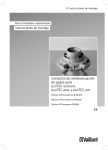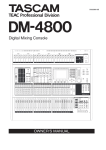
1
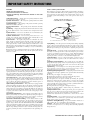
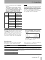
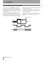
D00671100A
Professional Digital Surround Monitor Controller
OWNER’S MANUAL
Ü
ÿ
Ÿ
CAUTION: TO REDUCE THE RISK OF ELECTRIC SHOCK, DO NOT
REMOVE COVER (OR BACK). NO USER-SERVICEABLE PARTS
INSIDE. REFER SERVICING TO QUALIFIED SERVICE PERSONNEL.
The lightning flash with arrowhead symbol, within an equilateral triangle, is intended to alert
the user to the presence of uninsulated “dangerous voltage” within the product’s enclosure
that may be of sufficient magnitude to constitute a risk of electric shock to persons.
The exclamation point within an equilateral triangle is intended to alert the user to the presence of important operating and maintenance (servicing) instructions in the literature
accompanying the appliance.
This appliance has a serial number
located on the rear panel. Please record
the model number and serial number
and retain them for your records.
Model number
Serial number
WARNING: TO PREVENT FIRE OR SHOCK
HAZARD, DO NOT EXPOSE THIS
APPLIANCE TO RAIN OR MOISTURE.
Important Safety Precautions
IMPORTANT (for U.K. Customers)
For U.S.A
TO THE USER
DO NOT cut off the mains plug from this equipment.
If the plug fitted is not suitable for the power points in your home or
the cable is too short to reach a power point, then obtain an
appropriate safety approved extension lead or consult your dealer.
If nonetheless the mains plug is cut off, remove the fuse and dispose
of the plug immediately, to avoid a possible shock hazard by
inadvertent connection to the mains supply.
If this product is not provided with a mains plug, or one has to be
fitted, then follow the instructions given below:
IMPORTANT: The wires in this mains lead are coloured in
accordance with the following code:
GREEN-AND-YELLOW
BLUE
BROWN
: EARTH
: NEUTRAL
: LIVE
This equipment has been tested and found to
comply with the limits for a Class A digital device,
pursuant to Part 15 of the FCC Rules. These
limits are designed to provide reasonable
protection against harmful interference when the
equipment is operated in a commercial
environment. This equipment generates, uses,
and can radiate radio frequency energy and, if
not installed and used in accordance with the
instruction manual, may cause harmful
interference to radio communications.
Operation of this equipment in a residental area
is likely to cause harmful interference in which
case the user will be required to correct the
interference at his own expense.
WARNING: This apparatus must be earthed.
As the colours of the wires in the mains lead of this apparatus may
not correspond with the coloured markings identifying the terminals
in your plug proceed as follows:
The wire which is coloured GREEN-and-YELLOW must be
connected to the terminal in the plug which is marked by the letter
E or by the safety earth symbol ç or coloured GREEN or GREENand-YELLOW.
The wire which is coloured BLUE must be connected to the terminal
which is marked with the letter N or coloured BLACK.
The wire which is coloured BROWN must be connected to the
terminal which is marked with the letter L or coloured RED.
When replacing the fuse only a correctly rated approved type should
be used and be sure to re-fit the fuse cover.
IF IN DOUBT — CONSULT A COMPETENT ELECTRICIAN.
CAUTION
Changes or modifications to this equipment not
expressly approved by TEAC CORPORATION
for compliance could void the user’s authority to
operate this equipment.
For the consumers in Europe
WARNING
This is a Class A product. In a domestic environment, this
product may cause radio interference in which case the user
may be required to take adequate measures.
Pour les utilisateurs en Europe
AVERTISSEMENT
Il s’agit d’un produit de Classe A. Dans un environnement
domestique, cet appareil peut provoquer des interférences
radio, dans ce cas l’utilisateur peut être amené à prendre
des mesures appropriées.
Für Kunden in Europa
For Canada
AC POWER CORD CONNECTION
CAUTION:
TO PREVENT ELECTRIC SHOCK, MATCH
WIDE BLADE OF PLUG TO WIDE SLOT,
FULLY INSERT.
CORDE DE CONNEXION CA
ATTENTION:
POUR ÉVITER LES CHOCS ÉLECTRIQUES, INTRODUIRE LA LAME LA
PLUS LARGE DE LA FICHE DANS LA
BORNE CORRESPONDANTE DE LA
PRISE ET POUSSER JUSQU’AU FOND.
2
TASCAM DS-M7.1 Owner’s Manual
Warnung
Dies is eine Einrichtung, welche die Funk-Entstörung nach
Klasse A besitzt. Diese Einrichtung kann im Wohnbereich
Funkstörungen versursachen ; in diesem Fall kann vom
Betrieber verlang werden, angemessene Maßnahmen
durchzuführen und dafür aufzukommen.
The equipment draws nominal non-operating power from the
AC outlet with its POWER switch in the off position.
IMPORTANT SAFETY INSTRUCTIONS
CAUTION:
… Read all of these Instructions.
… Save these Instructions for later use.
… Follow all Warnings and Instructions marked on the audio
equipment.
1) Read Instructions — All the safety and operating instructions should
be read before the product is operated.
2) Retain Instructions — The safety and operating instructions should
be retained for future reference.
3) Heed Warnings — All warnings on the product and in the operating
instructions should be adhered to.
4) Follow Instructions — All operating and use instructions should be
followed.
5) Cleaning — Unplug this product from the wall outlet before cleaning.
Do not use liquid cleaners or aerosol cleaners. Use a damp cloth for cleaning.
6) Attachments — Do not use attachments not recommended by the
product manufacturer as they may cause hazards.
7) Water and Moisture — Do not use this product near water — for
example, near a bath tub, wash bowl, kitchen sink, or laundry tub; in a wet
basement; or near a swimming pool; and the like.
8) Accessories — Do not place this product on an unstable cart, stand,
tripod, bracket, or table. The product may fall, causing serious injury to a
child or adult, and serious damage to the product. Use only with a cart,
stand, tripod, bracket, or table recommended by the manufacturer, or sold
with the product. Any mounting of the product should follow the manufacturer’s instructions, and should use a mounting accessory recommended by
the manufacturer.
9) A product and cart combination should be moved with care. Quick stops,
excessive force, and uneven surfaces may cause the product and cart combination to overturn.
10) Ventilation — Slots and openings in the cabinet are provided for ventilation and to ensure reliable operation of the product and to protect it
from overheating, and these openings must not be blocked or covered. The
openings should never be blocked by placing the product on a bed, sofa,
rug, or other similar surface. This product should not be placed in a built-in
installation such as a bookcase or rack unless proper ventilation is provided
or the manufacturer’s instructions have been adhered to.
11) Power Sources — This product should be operated only from the
type of power source indicated on the marking label. If you are not sure of
the type of power supply to your home, consult your product dealer or local
power company. For products intended to operate from battery power, or
other sources, refer to the operating instructions.
12) Grounding or Polarization — This product may be equipped with a
polarized alternating-current line plug (a plug having one blade wider than
the other). This plug will fit into the power outlet only one way. This is a
safety feature. If you are unable to insert the plug fully into the outlet, try
reversing the plug. If the plug should still fail to fit, contact your electrician
to replace your obsolete outlet. Do not defeat the safety purpose of the
polarized plug.
13) Power-Cord Protection — Power-supply cords should be routed so
that they are not likely to be walked on or pinched by items placed upon or
against them, paying particular attention to cords at plugs, convenience
receptacles, and the point where they exit from the product.
14) Outdoor Antenna Grounding — If an outside antenna or cable
system is connected to the product, be sure the antenna or cable system is
grounded so as to provide some protection against voltage surges and builtup static charges. Article 810 of the National Electrical Code, ANSI/NFPA
70, provides information with regard to proper grounding of the mast and
supporting structure, grounding of the lead-in wire to an antenna discharge
unit, size of grounding conductors, location of antenna-discharge unit, connection to grounding electrodes, and requirements for the grounding electrode.
"Note to CATV system installer:
This reminder is provided to call the CATV system installer’s attention to
Section 820-40 of the NEC which provides guidelines for proper grounding
and, in particular, specifies that the cable ground shall be connected to the
grounding system of the building, as close to the point of cable entry as
practical.
Example of Antenna Grounding as per
National Electrical Code, ANSI/NFPA 70
ANTENNA
LEAD IN
WIRE
GROUND
CLAMP
ANTENNA
DISCHARGE UNIT
(NEC SECTION 810-20)
ELECTRIC
SERVICE
EQUIPMENT
GROUNDING CONDUCTORS
(NEC SECTION 810-21)
GROUND CLAMPS
POWER SERVICE GROUNDING
ELECTRODE SYSTEM
(NEC ART 250. PART H)
NEC - NATIONAL ELECTRICAL CODE
15) Lightning — For added protection for this product during a lightning
storm, or when it is left unattended and unused for long periods of time,
unplug it from the wall outlet and disconnect the antenna or cable system.
This will prevent damage to the product due to lightning and power-line
surges.
16) Power Lines — An outside antenna system should not be located in
the vicinity of overhead power lines or other electric light or power circuits,
or where it can fall into such power lines or circuits. When installing an
outside antenna system, extreme care should be taken to keep from touching such power lines or circuits as contact with them might be fatal.
17) Overloading — Do not overload wall outlets, extension cords, or
integral convenience receptacles as this can result in risk of fire or electric
shock.
18) Object and Liquid Entry — Never push objects of any kind into
this product through openings as they may touch dangerous voltage points
or short-out parts that could result in a fire or electric shock. Never spill
liquid of any kind on the product.
19) Servicing — Do not attempt to service this product yourself as opening or removing covers may expose you to dangerous voltage or other
hazards. Refer all servicing to qualified service personnel.
20) Damage Requiring Service — Unplug this product from the wall
outlet and refer servicing to qualified service personnel under the following
conditions:
a) when the power-supply cord or plug is damaged.
b) if liquid has been spilled, or objects have fallen into the product.
c) if the product has been exposed to rain or water.
d) if the product does not operate normally by following the operating
instructions. Adjust only those controls that are covered by the operating
instructions as an improper adjustment of other controls may result in
damage and will often require extensive work by a qualified technician to
restore the product to its normal operation.
e) if the product has been dropped or damaged in any way.
f ) when the product exhibits a distinct change in performance – this
indicates a need for service.
21) Replacement Parts — When replacement parts are required, be
sure the service technician has used replacement parts specified by the
manufacturer or have the same characteristics as the original part.
Unauthorized substitutions may result in fire, electric shock, or other
hazards.
22) Safety Check — Upon completion of any service or repairs to this
product, ask the service technician to perform safety checks to determine
that the product is in proper operating condition.
23) Wall or Ceiling Mounting — The product should be mounted to a
wall or ceiling only as recommended by the manufacturer.
24) Heat — The product should be situated away from heat sources such
as radiators, heat registers, stoves, or other products (including amplifiers)
that produce heat.
TASCAM DS-M7.1 Owner’s Manual 3
Table of Contents
1 – About the unit
Installing the DS-M7.1.................................6
2 – Parts of the DS-M7.1
Front panel...................................................8
Function keys.................................................. 9
Rear panel ....................................................11
3 – Connections
Connecting the console ..............................13
Connecting the tracking recorder ..............13
Connecting the mastering (stem) recorder14
A note on the word clock ...........................14
Inverting the word clock................................ 15
Word clock errors ........................................... 15
Inserts...........................................................16
Monitor connections ...................................16
Other monitoring settings............................. 17
Control room stereo inputs ........................17
Dimmer and mute control connections .....18
4 – Routing and patching
Choosing the surround format...................19
A note on LCRS ............................................... 20
Configuring the Input Summing Router....... 20
Matching output channels to
surround channels....................................... 20
5 – Using the DS-M7.1
Muting and soloing.....................................21
Soloing ............................................................ 21
Bass management .......................................21
4
TASCAM DS-M7.1
Type 1 bass management...............................23
Type 2 bass management...............................23
High speed operation................................. 23
6 – Note on DS-M7.1 usage
7 – Downmixing
A note on the mono downmix ......................25
7.1 formats .................................................. 26
6.1 format.................................................... 28
5.1 format.................................................... 30
LCRS format................................................. 32
LR format..................................................... 33
8 – Specifications
Analog connections ........................................34
AES/EBU connections......................................34
Specifications .............................................. 35
I/O specifications.............................................35
Analog monitor section..................................35
Analog CR inputs (stereo) ..............................35
Audio performance.........................................36
Analog outputs ...............................................36
Analog inputs..................................................36
General specifications.....................................37
Dimensional drawings....................................37
Making up a remote control cable ............ 38
Standard cable ................................................38
Extended cable................................................38
Block diagram ............................................. 39
1 – About the unit
The TASCAM DS-M7.1 is designed to help you
manage the monitoring of mixes of surround sound
projects.
CAM DM-24 and digital multitrack (tracking)
recorders as well as the multitrack recorder being
used to master the surround mix (the stem recorder),
the DS-M7.1 can be used for monitoring of the mix
as it comes off the console, as well as the recorded
mix from the mastering recorder, with the push of
one front panel key.
All major surround formats are supported, from
LCRS to 7.1.
Providing flexible switching and routing facilities
between a digital recording console such as the TAS-
Out
DS-M7.1
Surround
Monitoring
System
Insert Device
(e.g. Surround
Encoder/Decoder)
Output Router
In
Input Summing Router
In
TRK
Recorder
I/O
BUS/
RTN
Master
Recorder
I/O
Out
Mastering
Recorder
In
Tracking
Recorder
Out
Console I/O
Note that mastered tracks
(with or without Insert)
are monitored as RTN.
Inputs from the console
are monitored as BUS
Recorder
Returns
Buss
Outputs
Digital Mixing Console
The signals are switched and routed in the digital
domain, allowing the highest possible quality to be
maintained throughout the system.
Monitoring signals are output in both digital and analog format, and either can be selected as best suits the
needs of the facility in which the DS-M7.1 is
installed.
Downmixing is an important part of the surround mix
process, and the DS-M7.1 allows the operator to
select from a very wide range of downmix options
and settings.
Bass management for monitoring comparisons with
consumer-oriented systems which lack a dicrete LFE
channel is well supported, with user-selectable crossover and level settings, etc.
Connections are made using industry-standard
cables, and the slots for up to three optional
TASCAM expansion cards provide great flexibility,
TASCAM DS-M7.1 5
1 – About the unit
allowing almost every common industry format to be
supported by the DS-M7.1.
Full calibration facilities are provided, with a built-in
pink noise generator, to allow for quick, easy and
accurate setup of the unit. Channel delay is provided
to compensate for acoustic delay when surround
speakers are used in a large space.
An analog or digital insert can be placed in the monitoring path, in order to hear the surround mix through
a surround encoder. This is useful for hearing the
effect of the encoding process.
Muting and soloing of individual channels, with flexible soloing options, allows checking of any desired
combination of surround channels.
SPL indication and control is available from the front
panel, allowing the surround monitoring to be carried
out accurately, according to the different guidelines
and standards within the industry.
A dedicated pair of analog stereo inputs can be fed
from the console’s main control room outputs, allowing the same speaker/amplifier system to be used for
the L and R channels in both surround and stereo
operation modes. The last pair of the surround speakers (channels 7 and 8) can also be dedicated as smallalternative stereo speakers when the primary
surround application is 5.1 or LCRS.
For flexibility, the front panel controls can be
removed and connected to the main unit in the
machine room, allowing full control to be maintained
from the listening position.
The unit itself is simple and easy to use, taking
advantage of a menu-driven 20x4 alphanumeric display and rotary encoder system, with important mode
keys illuminated for quick verification of their status.
This manual accompanies the unit, together with a
Setup Guide, which should be used when you are
first setting up and calibrating the unit.
For best results we recommend that you follow these
procedures regarding level and delay adjustment
whenever you make a substantial change to your
monitoring environment.
Installing the DS-M7.1
When you unpack the DS-M7.1, you should find, in
addition to this manual:
Do not install the unit in an enclosed space (bookcase, etc.).
• A rack-mounting kit
• A standard power cable whose plug should match
the one for your region.
• A Setup Guide
• Warranty information, etc.
If any of these is missing, contact your TASCAM
distributor.
The DS-M7.1 is designed to fit into 3U of standard
19” rack space. Remove the feet before installing it
in a rack. We suggest that you leave at least 1U of
space above the unit to allow for cooling.
Always check that the power requirements printed on
the rear panel of the unit match those available in
your working environment. If they do not, or if you
are in any doubt, consult a qualified electrician.
Temperature considerations The ambient
operating temperature should be between 5°C and
40°C (41°F and 104°F).
Connections All connections to and from the DSM7.1 should be made and broken with the power
turned OFF.
6 TASCAM DS-M7.1
1 – About the unit
Using the front panel as a remote control
unit When you use the front panel as a remote con-
nector, where the cable may be routed more conveniently.
trol unit, you have the choice of using either the front
or rear 9-pin D-sub connector. If the DS-M7.1 is to
be installed in a machine room some distance from
the mixing location, we suggest using the rear con-
Follow the instructions given here (“Making up a
remote control cable” on page 38) when making up a
cable for use with the remote control. If you do not
follow these instructions, there is a risk of incorrect
operation, or even damage to the unit.
TASCAM DS-M7.1 7
2 – Parts of the DS-M7.1
Front panel
The part of the front panel of the unit which houses
the display and controls can be removed and connected via an appropriate cable, up to 20m (60ft.) in
length by turning the captive thumbscrews at the top
of the panel counterclockwise.
Retaining lug on main
unit front panel
Retaining hole in
removable front
panel
1
2
Note that the front panel is retained by the thumbscrews, and when it is removed from or replaced on
the main unit, care must be taken to match the retaining hole on the front panel with the retaining lug on
the main unit, as shown here:
When removed in this way, the front panel can be
used as a remote control unit, with the main unit
located in the machine room of the studio facility,
together with the multitrack and mixdown recorders.
See “Making up a remote control cable” on page 38
regarding the production of a suitable cable.
3 45678 9 A B
C
D
E
FGHIJKLM
1 POWER switch and indicator Press to
turn the power on and off.
NOTE
To avoid possible damage to the DS-M7.1 and to other
units or your ears, always make sure that the volume of
the amplifier connected to the DS-M7.1 which is driving
the monitor speakers is turned down before turning the
DS-M7.1 on or off.
2 REMOTE IN 2 Connect the front panel
(remote control) to this 9-pin D-sub connector using
8
TASCAM DS-M7.1
a suitable cable. An alternative connector is provided
on the rear panel.
3 DISPLAY This backlit 20x4 alphanumeric
display shows the parameters and settings of the unit.
NOTE
Note that the display also serves as a clock warning indicator. If the selected word clock source is not available
or is invalid, the display flashes and a message is displayed. See “Word clock errors” on page 15.
2 – Parts of the DS-M7.1
Function keys
These keys all have two functions: the unshifted
function, as shown by the label above the keys, and
the color-coded (to match the SHIFT key) shifted
function, as shown by the lower label. The shifted
function is enabled when the SHIFT indicator is lit.
4 STATUS/INPUT The STATUS key brings up
the Status screen, where the settings relating to the
master status of the system can be viewed (but not
changed).
As the INPUT key, it is used to route and assign the
inputs.
5 SYSTEM/OUTPUT As the SYSTEM key,
system settings are made on the screen brought up by
pressing this key.
As the OUTPUT key, it enables assignment of the
monitor outputs to the channels of the selected surround format.
6 INSERT/DELAY The DS-M7.1 allows either
an analog or digital insert loop in the monitoring
path. Use the INSERT key to control this insert.
In shifted mode, the DELAY key is used to compensate for speaker placement. See the Setup Guide for
details.
7 DOWNMIX/TRIM Downmixing refers to the
practice of monitoring a surround mix “folded down”
to a format with fewer channels, in order to check
mix compatibility. The DS-M7.1 allows you, for
example, to hear how a 5.1 mix will sound when
played through a 2-speaker stereo system. Use this to
set up the downmix parameters.
As the shifted TRIM key, this key is used to set up the
relative levels of the surround channels. See the
Setup Guide for details.
8 BASS MGT/TEST Used to select the type of
Bass Management used, and to set up the subwoofer
crossover frequency, relative level, etc. for when bass
management is enabled (see “Bass management” on
page 21).
As the shifted TEST key, it is used to set up the pink
noise parameters for level testing. See the Setup
Guide for details.
9 SHIFT key and indicator This latching
shift key alters the behavior of the function keys
listed above. It also is used with the DOWN MIX key
for mono downmixing.
A VALUE Use this rotary encoder to set the values shown on the display.
B CURSOR keys Use these keys to navigate
between the parameters shown on the display.
C MUTE CONTROL keys and
indicators These correspond to the channels of the
different surround formats supported by the DSM7.1. When a surround format is selected, the indicators of those channels which are valid for the format are lit. For example, if 5.1 is selected, the L, C,
R, LS, RS and LFE indicators are lit.
The keys act as monitor mute keys or solo keys
(depending on the status of the SOLO/MUTE key,
and are also used for selecting channels when setting
up the relative levels of the channels (see the Setup
Guide for details).
D ALT SPK Pressing this key selects speakers
connected to the LC and RC channels. When in surround mode, pressing this key automatically performs an LR downmix to the LC and RC channels.
E SPL REFERENCE indicator and
LEVEL control Use these to set and view the SPL
level output by the DS-M7.1 when it is properly calibrated. See the Setup Guide for full details of its
operation and its relationship to the software SPL
setting.
NOTE
If the output level is adjusted with this control so that it
exceeds the level set in the LCD menu (see the Setup
Guide), there is a risk of clipping and degradation of
sound quality.
F SOLO/MUTE Switches the function of the
MUTE CONTROL keys between muting and soloing
(the type of solo mode, exclusive or mix, is userselectable).
G SRND/ST Switches easily between the
selected surround format from the CONSOLE or
MASTER I/O connectors and stereo (input from the
dedicated CR stereo inputs on the rear panel).
H BUS/RTN Switches monitoring between the
bus inputs (from the mixing console—the indicator is
unlit) and the return inputs (from the mixdown
recorder—the indicator is lit).
The default as shipped from the factory is bus (the
indicator is unlit).
TASCAM DS-M7.1 9
2 – Parts of the DS-M7.1
I TEST Used in setup to turn the internal pink
noise generator on and off. See the Setup Guide for
details.
K BASS MGT Turns the bass management
function on and off (settings are made with the BASS
MGT function key)
J DOWN MIX/MONO Switches between the
L MUTE ALL Cuts all the monitor signals
selected surround format and the currently-selected
downmix mode (the downmix mode is selected using
the SYSTEM function key).
simultaneously.
When pressed together with the SHIFT key, this key
downmixes directly to mono from any surround format.
10 TASCAM DS-M7.1
M DIM Reduces the monitor output by a softwareselectable amount.
The default value, as shipped from the factory, is an
attenuation of –20dB.
2 – Parts of the DS-M7.1
Rear panel
See the section on Connections for details of how to
make connections to and from the DS-M7.1.
1
2
3 4 7 8
with three expansion slots, which can take different
types of I/O card. Consult your TASCAM dealer for
details concerning the availability and the fitting of
these cards. When a card is fitted, it can be used as an
alternative to one of the three connectors immediately to the right of the slots, as described below.
NOTE
Although an analog IF-AN/DM card may be fitted in any
slot, only one such card may be fitted at a time.
2 SLOT 1/CONSOLE I/O (TDIF) This 25pin D-sub connector sends and receives up to eight
channels of digital audio in TDIF format to and from
a suitably-equipped digital mixing console such as
the TASCAM DM-24. If a card is fitted in slot 1, it
may be used as an alternative to this connector.
3 SLOT 2/TRK RECORDER I/O (TDIF)
This 25-pin D-sub connector sends and receives up to
eight channels of digital audio in TDIF format to and
from a suitably-equipped multitrack recorder, such as
the TASCAM DTRS series, or MX-2424 recorders.
If a card is fitted in slot 2, it may be used as an alternative to this connector.
4 SLOT 3/INSERT I/O (AES/EBU) This
25-pin D-sub connector sends and receives eight
channels of digital audio in AES/EBU format. It can
be used for inserting a surround encoder/decoder in
the monitoring path. If a card is fitted in slot 3, it may
be used as an alternative to this connector.
C
6
5
1 Expansion slots The DS-M7.1 is fitted
9 AB
NOTE
When making connections to the DS-M7.1 using the
AES/EBU connectors, note that channels 1 and 2 must
always contain some signal. If there is no signal in these
two channels, no other AES/EBU channels can be
received. Also note that if the preamble is not correctly
received on a pair of AES/EBU input channels, those
channels will be muted.
5 MONITOR OUTPUTS There are two sets of
monitor outputs, which work in parallel, providing
up to eight channels of surround monitor outputs
apiece. Both are output from 25-pin D-sub connectors and require appropriate “breakout” cables (consult your dealer for details). The ANALOG
connectors work as balanced +4dBu outputs, while
the AES/EBU connector provides digital audio in
AES/EBU format.
6 STEREO CR INPUT These balanced
+4dBu inputs allow the stereo CR outputs from a
mixing console to be fed into the DS-M7.1, allowing
the same amplifier/speaker monitoring system to be
used for surround and stereo monitoring, without
repatching.
NOTE
Note the relationship between analog and digital signal
levels on the DS-M7.1. The maximum analog level is
+24dBu, equivalent to 0 dBFS digital. The nominal level
is +4dBU, corresponding to a digital level of –20dBFS.
7 WORD IN Use this BNC connector to receive
an external word clock signal. The 75Ω switch
allows termination to be set ON or OFF (usually ON).
TASCAM DS-M7.1 11
2 – Parts of the DS-M7.1
8 MASTER RECORDER I/O There are
three sets of connectors for connecting the master
recorder: TDIF-1 (combined input and output), ADAT
(separate input and output “lightpipe” connectors)
and AES/EBU (combined input and output).
9 REMOTE IN 1 Use this as an alternative to
the front panel REMOTE IN 2 connector when using
the front panel as a remote control. See “Making up a
remote control cable” on page 38 for details.
A RS-232C Reserved for future software
upgrades.
B MUTE/DIMMER This 3.5 mm stereo mini
jack socket is used to connect switches which can be
used for remote MUTE ALL/DIM operation. Con-
12 TASCAM DS-M7.1
nect tip to sleeve for the mute control, and ring to
sleeve for the dimmer. Switches used in this way are
active when closed, and should be non-latching. See
“Dimmer and mute control connections” on page 18.
C ~ IN (power input) Use the supplied power
cord to connect the DS-M7.1 to the power supply.
Ensure that the power supply is the correct voltage
(as marked on the rear panel of the unit). If you are in
any doubt, consult a qualified electrician.
NOTE
Always connect and disconnect the power with the
power switch on the front panel of the DS-M7.1 turned
OFF. If the power cord is connected or disconnected
with this switch on, there is a risk of damage to the
unit.
3 – Connections
This section describes not only the connections you
make between other equipment and the DS-M7.1, but
also the software steps necessary to make that other
equipment recognizable by and usable with the unit.
Read this section carefully, especially the section on
word clock, as it is essential to the proper operation
of your system, and may even result in damage to
your equipment if the appropriate steps are not carried out.
NOTE
When making connections between the DS-M7.1 and
other equipment, whether audio or control, both the
DS-M7.1 and the other equipment must be turned off,
otherwise damage may be caused to the DS-M7.1 and/
or the other equipment.
Only use TASCAM-supplied and TASCAM-approved
cables when making TDIF connections to the DS-M7.1.
Though the cables and connectors may resemble computer cables, they serve different purposes, and meet a
different set of specifications. The use of cables other
than TASCAM cables will at best cause the equipment
to work erratically, and at worst cause damage to the
equipment.
Also note that while the TDIF and AES/EBU connectors
on this unit are physically identical, the wiring and signals passed through them are very different. Take care
to connect only TDIF equipment to TDIF connectors, and
AES/EBU equipment to AES/EBU connectors, otherwise
damage may occur to your equipment.
If the use of cables other than TASCAM cables causes or
results in damage, the warranty is voided.
It is assumed that all necessary optional cards have
been fitted to the DS-M7.1.
See the diagram on page 5 as well as the block diagram (“Block diagram” on page 39) if you are unsure
of signal flow within the DS-M7.1.
Consult your TASCAM dealer for details of suitable
approved cables that may be used when using your
DS-M7.1 with other equipment.
If you need an extension to the front panel cable to
allow the front panel to be used as a remote control
unit, see “Making up a remote control cable” on
page 38.
Connecting the console
The console can be connected to the built-in
CONSOLE I/O connector, or to an optional card fitted in slot 1.
Inputs from the console Typically, the console’s busses are connected to the DS-M7.1 inputs.
They are sent simultaneously to the tracking and
mastering recorders, and may be monitored from the
DS-M7.1 as the BUS signals. Since these are used for
both tracking and mastering, obviously, the console
signal paths must be repatched when the mode is
changed. No reconnections need to be made on the
DS-M7.1.
Outputs to the console The returns from the
DS-M7.1 to the console are driven (as a “thru”
assignment) by the tracking recorder (track returns)
and should be assigned appropriately on the console,
following normal working practice. They may not be
monitored directly from the DS-M7.1.
When this connection, together with all other connections, have been made, you should set up the DSM7.1 to recognize the appropriate the console source
(TDIF or slot), as described here.
1
Press the SYSTEM key and press the cursor
keys until the cursor highlights the
ConsSel parameter:
[SYSTEM]
>
MasterSel
2
TDIF
ConsSel
TDIF
TrkRecSel
TDIF
Use the VALUE control to select between
TDIF and SLOT1.
When this is done, the inputs and outputs must be
routed appropriately, as described later.
Connecting the tracking recorder
The tracking (multitrack) recorder can be connected
to the built-in TRK RECORDER I/O TDIF connector,
or to an optional card fitted in slot 2.
Inputs from the tracking recorder These
connect to the recorder outputs. They are routed to
TASCAM DS-M7.1 13
3 – Connections
the console outputs, and may not be monitored
directly from the DS-M7.1.
1
Outputs to the tracking recorder These
connect to the recorder inputs. These may be monitored as BUS signals from the DS-M7.1.
When this connection, together with all other connections, have been made, you should set up the DSM7.1 to recognize the appropriate tracking recorder
source (TDIF or slot), as described here.
Press the SYSTEM key and press the cursor
keys until the cursor highlights the
TrkRecSel parameter:
[SYSTEM]
2
>
MasterSel
TDIF
ConsSel
TDIF
TrkRecSel
TDIF
Use the VALUE control to select between
TDIF and SLOT2.
When this is done, the inputs and outputs must be
routed appropriately, as described later.
Connecting the mastering (stem) recorder
The mastering recorder can be connected to any of
the following: the built-in TDIF, ADAT “lightpipe” or
AES/EBU connector.
M7.1 to recognize the appropriate the tracking
recorder source (TDIF, AES/EBU or ADAT optical),
as described here.
Inputs from the mastering recorder These
1
are the outputs from the master recorder. They can be
passed through the insert device (described below) if
desired, and then monitored from the DS-M7.1 as the
RTN signals.
Press the SYSTEM key and press the cursor
keys until the cursor highlights the
MasterSel parameter:
[SYSTEM]
>
MasterSel
TDIF
Outputs to the mastering recorder These
ConsSel
TDIF
are the signals output from the console. They can be
passed through the insert device (described below) if
desired, and then monitored from the DS-M7.1 as the
BUS signals.
TrkRecSel
TDIF
When this connection, together with all other connections, have been made, you should set up the DS-
2
Use the VALUE control to select between
TDIF, AES/EBU and ADAT.
When this is done, the inputs and outputs must be
routed appropriately, as described later.
A note on the word clock
Note that the DS-M7.1 cannot act as the word clock
master in a digital system. It must therefore receive
its word clock from a master clock elsewhere in the
system, and this must be the only clock in the system.
Since the word clock is important to correct operation, not only of the DS-M7.1, but of the whole audio
system, an explanation of how to set up the word
clock is given here.
Use of more than one master clock in the system can
lead to serious sound degradation, and possible damage to speakers and equipment.
1
If the word clock setting in memory does not
correspond to the actual word clock connection physically present, the display will flash.
The word clock can be taken from either the dedicated WORD IN BNC connector, the console input
(or the equivalent slot) or the master recorder (any of
the three possible inputs).
2
Press the SYSTEM key and press the cursor
keys until the screen shows something like:
[SYSTEM]
ClockSel
If the dedicated WORD IN connector is used, be sure
to set the termination switch as determined by the
needs of the rest of your system.
<>
Console
TDIF
48kHz
3
With the cursor at the top field, use the
VALUE control to select between Word IN,
14 TASCAM DS-M7.1
3 – Connections
Console and MasterRec (mastering
recorder).
The second and third lines of the screen will
be automatically filled in depending on both
the source and the settings made elsewhere in
the system as described in “Routing and
patching” on page 19. Possible values are:
Source
Possible sources
High-speed connections cannot be made using the TASCAM DM-24 digital mixing console. They may not be
supported by other equipment, and you should check
carefully in the documentation of all the components of
your system to ensure that this is a valid option.
Only the analog and AES/EBU connections and option
cards support 96k operation on the DS-M7.1.
Possible sampling
frequencies (kHz)
Word In
Word In only
44.1, 48, 88.2, 96
Console
TDIF (internal)
44.1, 48
EX TDIF (slot)
44.1, 48
EX AES/EBU (slot)
44.1, 48 (normal),
88.2, 96 (high)
EX ADAT (slot)
44.1, 48
TDIF (internal)
44.1, 48
AES/EBU (internal)
44.1, 48 (normal),
88.2, 96 (high)
ADAT (internal)
44.1, 48
Master Rec
NOTE
Inverting the word clock
In some cases, the polarity of the word clock received
at the WORD IN connector may be inverted relative
to what the DS-M7.1 expects (since no industry standard has been universally adopted). In this case, you
may need to invert the polarity of the clock so that it
syncs accurately with the other devices in the setup.
1
Press the SYSTEM key, and use the cursor
keys until a screen similar to the following
appears:
[SYSTEM]
2
<>
LFEGain
+10dB
Solo
Exlusiv e
WordIN
Normal
Switch the WordIN parameter between
and Reverse.
Normal
Word clock errors
In the event of a word clock error, the display backlight flashes, the output is muted, and the screen
Error
Meaning
number
shows [SYSTEM] *n where n is a number representing the error, as explained below:
Appropriate action to take
0
No master clock.
Check the connections between the DS-M7.1 and the clock master, and check the settings on the clock master to ensure that it is actually outputting a word sync signal.
1
Master clock out of range (44.1 kHz)
2
Master clock out of range (48 kHz)
Check the settings of the clock master, and make sure that it is within ±6% of the
stated nominal frequency
3
Master clock out of range (88.2 kHz)
4
Master clock out of range (96 kHz)
TASCAM DS-M7.1 15
3 – Connections
Error
Meaning
number
Appropriate action to take
7
Frequency error
The master clock is not a recognized frequency (e.g. 32 kHz). Check the master settings and correct, if necessary.
8
AES/EBU preamble error (normal)
At normal sampling frequencies, the preamble of the AES/EBU signal acting as the
clock source cannot be read by the DS-M7.1. Check and correct settings on the clock
master.
9
AES/EBU preamble error (high-speed) At high sampling frequencies (88.2 kHz and 96 kHz), the preamble of the AES/EBU
signal acting as the clock source cannot be read by the DS-M7.1. Check and correct
settings on the clock master.
Inserts
Either analog or digital insert units can be connected
to operate after the BUS/RTN switch. These are
selectable pre- or post- the Input Summing Router.
These inserts can be pre- or post- the input summing
router (placed between the inputs and the RTN/BUS
selector switch) and always pre- the RTN/BUS
switch. See the block diagram at the end of this manual for details.
Either AES/EBU digital devices, or analog (standard
+4dBu balanced) may be used here. Note that when
making connections to an analog insert unit, because
of the nature of the connectors used, two connections
need to be made, one for input and one for output.
1
Press the INSERT key so that the screen
shows something like:
[INSERT]
State
DISABLED
Mode
POST
Return
ANALOG
SUM
2
There are three parameters. Use the cursor
keys to select them. First, select whether the
insert loop is enabled (ENABLED) or disabled (DISABLED).
3
Next, select the position of the insert loop, as
described above: either PRE SUM or
POST SUM (i.e. before or after the input
summing router).
4
Finally, set the Return type: ANALOG
(analog) or DIGITAL (digital).
After the connection has been made, you should set
up the insert as follows:
Monitor connections
There are two sets of monitor connections, analog
and digital.
The analog connections are standard balanced
+4dBu connections, and the digital outputs are in
AES/EBU format.
NOTE
The sampling frequency output from the digital monitor outputs is the input frequency. If you are mixing a
high sampling frequency project, you must therefore
make sure that your digital monitoring setup can handle these frequencies, or use the DS-M7.1’s analog monitoring ports.
The analog and digital signals are output in parallel,
and there is no switching between them.
16 TASCAM DS-M7.1
TIP
The AES/EBU monitoring signals can be used in parallel
with the analog monitoring signals to drive a suitablyequipped meter bridge.
However, there is one setting that can be made for the
AES/EBU digital ports; the “pick-off” point for the
monitoring.
This can be set so that all the downmix, bass management and delay settings, together with all muting and
soloing and level settings described in “Other monitoring settings” on page 17, are ignored, or so that
these settings take effect through the digital port.
This affects the digital outputs only—the analog outputs will always reflect these settings.
3 – Connections
1
Press the SYSTEM key, and use the cursor
keys until a screen similar to the following
appears:
[SYSTEM]
MonOut
2
<
Use the VALUE control to select between
POST (the digital signals mirror the analog
signals) and PRE (the parameters described
above are ignored).
POST
Other monitoring settings
There are other system settings related to the monitor
system, which affect the analog outputs and the digital outputs in “post” mode.
Surround level This sets the amount by which
the surround (rear speaker) level is attenuated.
1
These are the SPL Reference Level, the Dimmer
level, the Surround level and the LFE Gain.
Press the SYSTEM key, and use the cursor
keys until a screen similar to the following
appears:
SPL Reference Level sets the reference value of
[SYSTEM]
the SPL which will be used in the monitoring environment. See the Setup Guide for details of how this
works.
Dimmer
<>
-60dB
SPLRefLevel
82dB
SurroundLvl
-10dB
It is accessed and set in the screen described here,
however.
2
Dimmer level This sets the amount by which the
monitor signal is dimmed (or attenuated) when the
DIM key is active.
LFE gain This refers to the amount of relative gain
1
1
Press the SYSTEM key, and use the cursor
keys until a screen similar to the following
appears:
[SYSTEM]
Dimmer
2
added to the LFE channel.
<>
82dB
SurroundLvl
-10dB
Use the VALUE control to set the Dimmer
parameter value between –60dB and –10dB
in 5dB steps.
Press the SYSTEM key, and use the cursor
keys until a screen similar to the following
appears:
[SYSTEM]
-60dB
SPLRefLevel
Use the VALUE control to set the
parameter value to
between 0dB and –10dB in 1dB steps.
SurroundLvl
2
<>
LFEGain
+10dB
Solo
Exclusive
WordIN
Normal
Use the VALUE control to set the LFEGain
parameter value to any of the following values: 0, +6, +7, +8, +9 or +10 (dB).
Control room stereo inputs
These balanced +4dB inputs are used for a direct
feed of the master CR analog outputs (your console
may give these a different name, but they are the stereo outputs used for monitoring in the control room)
to the DS-M7.1.
These outputs can be monitored directly from the
DS-M7.1 using the SRND/ST key.
Note that the stereo inputs are subject to the same
downmix, delay, processing etc. as the surround
inputs. See the block diagram for details.
TASCAM DS-M7.1 17
3 – Connections
Dimmer and mute control connections
A remote box for mute (MUTE ALL) and dimmer
control may be made up and used so that the control
of these functions can be carried out from a location
in the listening environment other than the main mixing location.
than the open/closed status of the switch triggers the
change in the unit’s status.
Use non-latching push-to-make switches wired to a
common sleeve ground with the dimmer wired to
ring, and the mute to the tip of a standard 3.5mm stereo plug. The detection of the change in level, rather
See “Dimmer level” on page 17, “Dimming the output” on page 21 and “Muting all the channels” on
page 21.
A remote box fitted with these switches can operated
alongside the appropriate front panel switches (it
does not replace them).
External non-latching
switches
TIP
RING
3.5 mm jack
MUTE KEY
DIMMER KEY
SLEEVE
MUTE ALL
key
push
release
push
release
Push action only
is detected
MUTE ALL OFF
status
18 TASCAM DS-M7.1
ON
OFF
4 – Routing and patching
When the physical external connections have been
made, it is time to set up the internal connections
within the DS-M7.1 as described here.
Since project needs and applications vary, the DSM7.1 provides flexibility in the way in which incoming signals are received and monitored.
Choosing the surround format
First, you must decide in what format the incoming
signals are to be processed. The available options are:
7.1, 6.1, 5.1, LCRS (LS, RS), LCRS (CS) and LR.
LC
L
C
RC
These may be graphically represented in the following way (LR (stereo) is not shown, as it is assumed
the reader is familiar with this format!):
L
R
C
LFE
LS
LFE
LS
RS
CS
7.1 format
L
C
R
RS
6.1 format
R
L
C
R
RS
LS
CS
RS
LFE
LS
5.1 format
LCRS (LS,RS) format
L
C
R
CS
LCRS (CS) format
Consult one of the standard reference works on the
subject if you are unsure under which circumstances
each format is used (a note on the two LCRS formats
is given below).
Note how the placement of the speakers relative to
the listener is mirrored by that of the MUTE
CONTROL keys of the DS-M7.1 (except in the 7.1
mode).
To set the surround format and the routing of the
inputs through the input summing router (you may
want to consult the block diagram at this stage):
TASCAM DS-M7.1 19
4 – Routing and patching
1
With the SHIFT indicator lit, press the
STATUS/INPUT key so that the screen displays the following:
[INPUT
SUM
ROUTER]
Format
LCRS(LS,RS)
Input
Output
12345678
1
*-------
2
Use the cursor keys to navigate to the
set the value
(VALUE control) to one of those listed above.
Input parameter, and
As you select the surround pattern, note how the
green indicators under each MUTE CONTROL key
light and go out, reflecting the surround pattern you
have selected.
A note on LCRS
The DS-M7.1 supports two variants of the LCRS format to support a control room set up for 5.1 or 6.1
operation without the need to repatch the speakers.
LCRS (LS, RS) In the first of these format, a “phantom” speaker is created by attenuating the LS(S) sig-
nal by 3dB and then assigning it to the LS and RS
speakers.
LCRS (CS) This format assigns the LS(S) signal to
the LC(CS) speaker.
You should choose the appropriate LCRS format
depending on your control room setup.
Configuring the Input Summing Router
You should now configure the Input Summing
Router. This does not affect the physical output
assignments made by the Output Router but will
affect what goes to the insert in post mode.
Value control
to pick the desired Input
Summing Router output.
2
Since you may have more channels in the surround
format you are mixing to than you do offboard insert
equipment, you may need to combine more than one
input with the Input Summing Router before sending
the signals to an inserted device.
The DS-M7.1 allows you to do this, in the following
way.
1
Move the cursor to the bottom right of the
screen, representing the eight inputs of the
Input Summing Router, and use the cursor
and VALUE control to assign (*) or release
(-) an input to and from an output. When
this is done, repeat the first step for the next
Input Summing Router output.
Note that this way of working allows an input
channel to be assigned to more than one
monitor output, and a monitor output to be
fed by more than one input.
On the bottom line of the screen above, move
the cursor to the Output field, and use the
Matching output channels to surround channels
The next stage is to match the numbered output of
the Input Summing Router (as routed and summed
earlier) to the named surround output channels of the
surround pattern you have set up earlier. You may not
need to do this if your setup matches standard settings.
1
With the SHIFT indicator lit, press the
SYSTEM/OUTPUT key so that the screen displays something like the following:
2
Use the cursor keys and VALUE control to
navigate to the surround channels and assign
the outputs to them.
NOTE
The output router is always active. It cannot be
bypassed.
[OUTPUT]
L
1
C
3
R
2
LC
7
LFE
4
RC
8
LS
5
RS
6
20 TASCAM DS-M7.1
The screen above shows a 7.1 surround pattern. If you have picked another pattern, you
will see only those channels which are relevant to your pattern.
5 – Using the DS-M7.1
Once you have set up the connections, assigned the
inputs and outputs, and followed the procedures in
the Setup Guide, you can start using your DS-M7.1.
Dimming the output Press the DIM key to dim
the output by the amount set in “SPL Reference
Level” on page 17. The DIM key lights when active.
Return or bus? Use the RTN/BUS key to select
Alternative speakers A pair of speakers con-
between return inputs (the signal coming in from the
mastering recorder)—the key lights in this mode—
and bus inputs (from the console).
nected to the LC and RC outputs of the monitors can
be used as an alternative pair of speakers (e.g. nearfield reference) and accessed using the ALT SPK key.
This will automatically produce a stereo downmix to
these speakers.
Surround or stereo? Select either the surround
or the stereo program source (from the analog TRS
monitor inputs) using the SRND/ST key.
NOTE
This function is only useful for surround patterns that
do not use the LC and RC speakers. If these speakers are
used (7.1), the function is available, but not very useful.
Muting and soloing
Muting Typically, the MUTE CONTROL keys are
used to mute individual channels, or combinations of
channels, in the monitor mix.
Muting all the channels The MUTE ALL key
can be pressed so that it flashes, and mutes all channels together.
When the appropriate key(s) is/are pressed in this
mute mode, they light.
Soloing
The SOLO/MUTE key can be pressed so that it lights.
In this case, the MUTE CONTROL keys act as solo
keys and flash when they are active (soloing their
channel).
There are two methods of soloing, exclusive soloing
(only one channel at a time is soloed) and mix soloing, where channels are added to the mix one at a
time (the reverse of muting, where they are subtracted one at a time).
Exclusive versus mix solo To change between
1
Press the SYSTEM key, and use the cursor
keys until a screen similar to the following
appears:
[SYSTEM]
<>
LFEGain
2
+10dB
Solo
Exclusive
WordIN
Normal
Use the VALUE control to set the Solo
parameter value to Mix or Exclusive.
the two solo modes:
Bass management
Bass management refers to the ability to derive the
LFE output based on a crossover from the satellite
speakers instead of from the console LFE output bus.
This is useful for simulating various consumer
speaker systems which utilize bass management
instead of a discrete LFE channel.
There are two types: type 1, where the subwoofer
signal is created from the main channels, and type 2,
where the LFE channel is fed to the other channels to
create the illusion of a separate bass channel. See the
illustrations here:
Turn the selected bass management on or off with the
BASS MGT key under the SPL meter. When this is
off, the normal levels apply.
These two types are provided for the simulation of
systems with and without dedicated subwoofers.
Note that the bass management has nothing to do
with the actual mix to and from the tracking (stem)
recorder—it is purely for monitor signals.
Press the BASS MGMT function key (under the display) to enter the setup screen.
TASCAM DS-M7.1 21
5 – Using the DS-M7.1
The parameter to the left on the second line allows
you to choose between the two types: TYPE1 and
TYPE2.
80/100/120 Hz
48dB/oct
Type 1
L
HPF
L
C
HPF
C
R
HPF
R
LS
HPF
LS
HPF
RS
RS
-15 / 0 dB
(-15dB default)
LFE
SW
LPF
-5/ +10 dB
(-5dB default)
LC
LC
RC
RC
Type 2
80/100/120 Hz
48dB/oct
-12.0 dB
L
L
-1.5 dB
C
C
HPF
-12.0 dB
R
R
-1.5 dB
LS
RS
HPF
LS
HPF
RS
-15 dB
SUB
LFE
LPF
-5 dB
SW
LPF
(default OFF)
LC
LC
RC
RC
22 TASCAM DS-M7.1
5 – Using the DS-M7.1
Type 1 bass management
When type 1 bass management is selected, the screen
looks something like this:
[BASSMGT]
SUB
ON
LFE>LFE The amount of LFE signal added to the
TYPE1
MCH>LFE-15.0
FRQ
120
LFE>LFE
This is set together with the LFE>LFE parameter as
described below.
-5.0
FRQ The frequency at which the crossover occurs:
LFE monitor channel. This is set together with the
MCH>LFE parameter described above.
Two sets of values are available for these linked
parameters:
80, 100 or 120 (Hz).
MCH>LFE The amount of main channel signal (L,
C, R, LS, RS) added to the LFE monitor channel.
Set 1
Set 2
MCH>LFE
–15.0dB
0dB
LFE>LFE
–5.0dB
+10dB
Type 2 bass management
When type 2 bass management is selected, the screen
looks something like this:
[BASSMGT]L>LR>R-12.0
TYPE2
LFE>LR
Apart from the type, there are only two parameters
on this screen that can be changed:
SUB Turns the sub channel on and off.
-1.5
SUB
OFF
CLR>LFE-15.0
FRQ The frequency at which the crossover occurs:
FRQ
120
LFE>LFE
80, 100 or 120 (Hz).
-5.0
All other settings are fixed and are provided for
information only.
High speed operation
Remember that although the DS-M7.1 is capable of
high-speed operation (88.2kHz and 96kHz sampling
frequencies) as determined by the frequency of the
word clock source (see “A note on the word clock”
on page 14), as mentioned earlier, this is not an
option supported by the TASCAM DM-24 digital
mixing console, and it may not be supported by other
units.
Even if a high clock rate is selected in the SYSTEM
setup screen, the incoming clock at the BNC WORD
IN can be either the base rate (48k for 96k, or 44.1k
for 88.2k) of the selected high-speed rate or the
actual high-speed rate.
Always consult the documentation of other units
before attempting high-speed connections.
NOTE
When high-speed signals are received in AES/EBU format, and the preamble is not correctly detected on
channels 5 and 6, these channels, together with channels 7 and 8, will be muted.
TASCAM DS-M7.1 23
6 – Note on DS-M7.1 usage
Many pre-mixes for film are made that are greater
than 8 tracks. The DS-M7.1 can still be useful in
these conditions, as explained here.
If a large format (24 or more output busses) console
is used, a number (8 or 16) of the busses can be used
to feed the stem recorder.
Stem recorder tracks
return via faders
The returns from the stem recorder can then be fed
back through the console inputs and routed to a different set of eight busses, which are then used to feed
the DS-M7.1 for monitoring.
Although this does not allow BUS/RTN switching,
the DS-M7.1’s monitoring control (bass management
and downmix facilities, etc.) can still be used to great
effect in this environment.
Multitrack
recorder
Stem recorder
8 or 16 busses to
the stem recorder
Tracks for
mixing
Multi-bus mixing console
8 (or 6) busses containing stem tracks
sent for monitoring
DS-M7.1
24
TASCAM DS-M7.1
Monitoring
system
7 – Downmixing
Downmixing, as explained earlier, is the process of
folding a surround mix into a format using fewer
channels. This is done for the purpose of checking
compatibility.
Downmixing is enabled and disabled on the DSM7.1 using the DOWN MIX/MONO key under the
SPL readout and control. When downmixing is
active, the key is lit (it flashes in mono downmix
mode, see below).
Available downmix
targets
Source pattern
6.1
5.1
LR
MONO
5.1
LCRS
4.1
The settings for downmix are made using the
DOWNMIX function key.
1
Press the DOWNMIX function key so that the
screen shows something similar to the following:
LR
MONO
LCRS (both formats) - see “A
note on LCRS” on page 20
LR
LR
MONO
LR & LcRC
MONO
[DOWNMIX]
2
Pattern
7.1>5.1
LC>L,RC>R
-1.5dB
LC+RC>C
-4.5dB
The first parameter, Pattern, sets the
downmix “folddown” pattern. The patterns
available here depend on the source format
currently in use:
Available downmix
targets
Source pattern
7.1
5.1
LR
MONO
Depending on the value picked here, the other values
(that is, the amount by which the source busses are
attenuated before they are folded into the target busses) will change.
Note that some busses may pass through more than
one attenuator before reaching their destination.
These patterns are shown graphically, with an list of
the parameters and options available in each pattern.
The default downmix pattern for all source patterns is
LR.
MONO
A note on the mono downmix
The mono downmix is accessed using the shifted
DOWN MIX key. When the SHIFT key is held down
and the DOWN MIX/MONO key is pressed (whether it
is currently active or not), the mono downmix is
enabled.
Pressing the DOWN MIX/MONO key while it is flashing returns it to its previous status.
TASCAM DS-M7.1 25
7 – Downmixing
7.1 formats
L
L
L
L
R
R
R
R
C
C
C
mute
C
mute
LFE
mute
LS
mute
RS
mute
LC
mute
RC
-3/-4.5/-6dB
-4.5/-6/-7.5/
-9dB
LFE
LFE
LFE
-3/-6/-9/ dB
LS
LS
LS
-0/-3/-6/
RS
RS
RS
-3dB
LC
mute
LC
LC
mute
RC
RC
-1.5/-3/-4.5/-6dB
RC
-1.5/-3/-4.5/
-6dB
7.1 > 5.1
7.1 > LR
L
L
-3dB
R
C
R
mute
C
mute
LFE
mute
LS
mute
RS
mute
LC
mute
RC
-3/-4.5/-6dB
LFE
-3/-6/-9/
dB
LS
-0/-3/-6/
RS
-3dB
LC
-1.5/-3/-4.5/
-6dB
RC
7.1 > mono
26 TASCAM DS-M7.1
7 – Downmixing
7.1 > 5.1 In the 7.1 to 5.1 downmix, the attenuation
7.1 > mono In the 7.1 to mono downmix, the
values are:
attenuation values are:
Source > Target
Values in dB (default underscored)
Source > Target
Values in dB (default underscored)
LC>L, RC>R
-1.5, –3, –4.5, –6
C > L+R
–3, –4.5, –6
LC+RC > C
–4.5, –6, –7.5, –9
LFE>L+R
–3, –6, –9, –∞
LS,RS>L+R
0, –3, –6, –∞
LC,RC>L+R
–1.5, –3, –4.5, –6
7.1 > LR In the 7.1 to LR (stereo) downmix, the
attenuation values are:
Source > Target
Values in dB (default underscored)
C > L,R
–3, –4.5, –6
LFE>L,R
–3, –6, –9, –∞
LS,RS>L,R
0, –3, –6, –∞
LC+RC+c>L,R
–1.5, –3, –4.5, –6
TASCAM DS-M7.1 27
7 – Downmixing
6.1 format
L
L
L
L
R
R
R
R
C
C
C
mute
C
mute
LFE
mute
LS
mute
RS
mute
LC
mute
RC
-3/-4.5/-6dB
LFE
LFE
LFE
-3/-6/-9/ dB
LS
LS
LS
RS
RS
RS
LC
CS
(LC)
-0/-3/-6/
CS
(LC)
mute
-3/-4.5/-6dB
RC
RC
mute
B
-3/-6/-9/
RC
6.1 > 5.1
6.1 > LR
L
L
-3dB
R
R
C
mute
C
mute
LFE
mute
LS
mute
RS
mute
LC
mute
RC
-3/-4.5/-6dB
LFE
-3/-6/-9/
dB
LS
-0/-3/-6/
RS
CS
(LC)
-3/-6/-9/
RC
6.1 > mono
28 TASCAM DS-M7.1
7 – Downmixing
6.1 > 5.1 In the 5.1 to 5.1 downmix, the attenuation
6.1 > mono In the 6.1 to mono downmix, the
values are:
attenuation values are:
Source > Target
Values in dB (default underscored)
Source > Target
Values in dB (default underscored)
CS (LC)>LS,RS
-3, –4.5, –6
C > L+R
–3, –4.5, –6
LFE>L+R
–3, –6, –9, –∞
LS,RS>L+R
0, –3, –6, –∞
CS(LC)>L+R
–3, –6, –9, –∞
6.1 > LR In the 6.1 to LR (stereo) downmix, the
attenuation values are:
Source > Target
Values in dB (default underscored)
C > L,R
–3, –4.5, –6
LFE>L,R
–3, –6, –9, –∞
LS,RS>L,R
0, –3, –6, –∞
CS (LC)>L,R
–3, –6, –9, –∞
TASCAM DS-M7.1 29
7 – Downmixing
5.1 format
L
L
L
L
R
R
R
R
C
C
C
mute
C
-3/-4.5/-6dB
dB
-3/-6/-9/
-3/-6/-9/
LFE
dB
mute
LS
LFE
LFE
LFE
LS
LS
LS
RS
RS
RS
-3dB
RS
LC
mute
LC
LC
mute
LC
RC
mute
RC
RC
mute
RC
5.1 > LCRS
5.1 > 4.1
L
L
L
R
R
R
C
C
C
mute
-3/-4.5/-6dB
-3dB
R
mute
C
mute
LFE
mute
LS
-3/-4.5/-6dB
LFE
mute
-3/-6/-9/
L
LFE
LFE
-3/-6/-9/ dB
dB
LS
mute
LS
LS
-0/-3/-6/
-0/-3/-6/
RS
mute
RS
RS
mute
RS
LC
mute
LC
LC
mute
LC
RC
mute
RC
RC
mute
RC
5.1 > LR
30 TASCAM DS-M7.1
5.1 > mono
7 – Downmixing
5.1 > LCRS In the 5.1 to LCRS downmix, the attenuation values are:
5.1 > LR In the 5.1 to LR (stereo) downmix, the
attenuation values are:
Source > Target
Values in dB (default underscored)
Source > Target
Values in dB (default underscored)
LFE >C
–3, –6, –9, –∞
C >L,R
–3, –4.5, –6
LFE>L,R
–3, –6, –9, –∞
LFE>L,R
–3, –6, –9, –∞
LS,RS>L,R
0, –3, –6, –∞
5.1 > 4.1 In the 5.1 to 4.1 downmix, the attenuation
values are:
5.1 > mono In the 5.1 to mono downmix, the
attenuation values are:
Source > Target
C >L,R
Values in dB (default underscored)
–3,–4.5, –6
Source > Target
Values in dB (default underscored)
C > L+R
–3, –4.5, –6
LFE>L+R
–3, –6, –9, –∞
LS,RS>L+R
0, –3, –6, –∞
TASCAM DS-M7.1 31
7 – Downmixing
LCRS format
L
L
L
R
R
R
C
C
C
mute
-3dB
R
mute
C
mute
LFE
mute
LS
-3/-4.5/-6dB
-3/-4.5/-6dB
LFE
S
(LS)
L
mute
LFE
LFE
mute
LS
S
(LS)
-0/-3/-6/
-0/-3/-6/
RS
mute
RS
RS
mute
RS
LC
mute
LC
LC
mute
LC
RC
mute
RC
RC
mute
RC
LCRS > LR
As mentioned earlier, there are two LCRS configurations. The first is the LCRS (LS, RS) configuration,
This allows a control room set up for 5.1 or 6.1 to use
an LCRS configuraiton without repatching the speakers. This is possible, since the Ls and Rs speakers are
assigned the same signal, thereby creating a “phantom” Cs speaker.
The second is the LCRS (CS) configuration, where
the LS(S) signal is assigned to the CS speaker of a
6.1 configuration.
Both configurations use the same downmix settings,
as shown here.
32 TASCAM DS-M7.1
LCRS > mono
LCRS > LR In the LCRS to LR (stereo) downmix,
the attenuation values are:
Source > Target
Values in dB (default underscored)
C >L,R
–3, –4.5, –6
S(LS)>L,R
0, –3, –6, –∞
LCRS > mono In the LCRS to mono downmix, the
attenuation values are:
Source > Target
Values in dB (default underscored)
C >L+R
–3, –4.5, –6
S(LS)>L+R
0, –3, –6, –∞
7 – Downmixing
LR format
L
L
-3dB
R
C
R
mute
C
LFE
mute
LFE
LS
mute
LS
RS
mute
RS
LC
mute
LC
RC
mute
RC
LR to mono
LR > mono In the LR to mono downmix, there are
no parameters (changeable attenuation values)
TASCAM DS-M7.1 33
8 – Specifications
The following information is provided for reference
when connecting the DS-M7.1 to other equipment.
Always take care when making these connections.
13
This shows the pinouts when viewing the rear panel
of the DS-M7.1.
1
25
14
Analog connections
The pinouts for the 25-pin D-sub connectors used for
both analog input and analog output are as follows:
Pin
Signal
Pin
Signal
Pin
Signal
Pin
Signal
13
NC
14
CH. 8 –
15
CH. 7 +
16
CH. 7 Gnd
1
CH 8 +
2
CH. 8 Gnd
17
CH. 6 –
18
CH. 5 +
3
CH. 7 –
4
Ch. 6 +
19
CH. 5 Gnd
20
CH. 4 –
5
CH. 6 Gnd
6
CH. 5 –
21
CH. 3 +
22
CH. 3 Gnd
7
CH. 4 +
8
CH. 4 Gnd
23
CH. 2 –
24
CH. 1 +
9
CH. 3 –
10
CH. 2 +
25
CH. 1 Gnd
11
CH. 2 Gnd
12
CH. 1 –
AES/EBU connections
The pinouts The pinouts for the 25-pin D-sub connectors used for AES/EBU I/O (insert and monitor,
as well as are as follows:
Pin
Signal
Pin
Signal
1
D. Out 4 +
2
Gnd
3
D. Out 3 –
4
D. Out 2 +
5
Gnd
6
D. Out 1 –
7
D. In 4 +
8
Gnd
9
D. In 3 –
10
D. In 2 +
34
TASCAM DS-M7.1
Pin
Signal
Pin
Signal
11
Gnd
12
D. In 1 –
13
NC
14
D. Out 4 –
15
D. Out 3 +
16
Gnd
17
D. Out 2 –
18
D. Out 1 +
19
Gnd
20
D. In 4 –
21
D. In 3 +
22
Gnd
23
D. In 2 –
24
D. In 1 +
25
Gnd
8 – Specifications
Specifications
I/O specifications
CONSOLE I./O
TRK RECORDER I/O
MASTER RECORDER I/O
INSERT I/O
MONITOR OUTPUTS
WORD IN
MUTE/DIM remote connector
REMOTE IN (1 and 2)
RS-232C
TDIF-1 format (built-in) 8 channels each of input and output (25-pin D-sub) or
slot 1
TDIF-1 format (built-in) 8 channels each of input and output (25-pin D-sub) or
slot 2
TDIF-1 format (25-pin D-sub)
AES-1992 (AES/EBU) format (25-pin D-sub)
ADAT (TOSLINK “lightpipe” format) x 2 (built-in), 8 channels each of input and
output
AES/EBU (25-pin D-sub), balanced analog (25-pin D-sub x 2), 8 channels each
of input and output or slot 3
AES/EBU (25-pin D-sub), balanced analog (25-pin D-sub), 8 channels of output
BNC , TTL level with 75Ω termination switch
TRS 3.5mm jack (common sleeve, tip=mute, ring=dim), TTL level input (falling
edge detection)
9-pin D-sub connectors (1=front, 2=rear) for connection of the remote control
panel. Power +8V, Differential Tx and Rx
9-pin D-sub connector conforming to RS-232C standards
The CONSOLE, MASTER and INSERT connectors
may each have an optional slot card selected as alternative I/O sources.
These slots may be filled by any of the following (but
only one analog IF-AN/DM card may be fitted at a
time).
Also note that when such analog cards are fitted, the
headroom should be set on the cards to 20dB, using
the switches and jumpers on the cards, and following
the documentation supplied with thcards.
IF-AE/DM
AES-1992 (AES/EBU) — can be used with high-speed mode
IF-AD/DM
ADAT “lightpipe” interface (SYNC in this card is not available with the DS-M7.1)
IF-TD/DM
TDIF card (REMOTE OUT connector not available with DS-M7.1)
IF-AN/DM
Analog I/O (use with 20dB headroom) — can be used in high-sampling mode
All these cards use PCI 120-pin edge connectors and
conform to the TASCAM TDMCS standard.
Analog monitor section
Nominal output level
Maximum output level
Output impedance
DAC resolution
+4dBu
+24dBu
< 100Ω
24bits
Analog CR inputs (stereo)
Nominal input level
Maximum input level
Input impedance
ADC resolution
+4dBu
+24dBu
> 10kΩ
24bits
TASCAM DS-M7.1 35
8 – Specifications
Audio performance
Analog outputs
Master recorder input(AES/EBU) -> Monitor output(Analog)
T.H.D
< 0.004%
1kHz 0dBFSinput, Fs=48kHz
S/N
> 113dB
Fs=48kHz, A-weight
Dynamic range
> 113dB
1kHz -60dBFS input, Fs=48kHz, A-weight
Frequency response
< ±0.5dB
20Hz-20kHz, 1kHz 0dBFS input, Fs=48kHz
< +0.5/-1.5dB
20Hz-40kHz, 1kHz 0dBFS input, Fs=96kHz
> 100dB
100dB1kHz 0dBFS input, Fs=48kHz
Crosstalk
Master recorder input(AES/EBU) -> Analog insert output(SLOT3 : IF-AN/DM)
T.H.D
< 0.006%
1kHz 0dBFS input, Fs=48kHz
S/N
> 111dB
Fs=48kHz, A-weight
Dynamic range
> 111dB
1kHz -60dBFS input, Fs=48kHz, A-weight
Frequency response
< ±0.5dB
20Hz-20kHz, 1kHz 0dBFS input, Fs=48kHz
< ±1.0dB
20Hz-40kHz, 1kHz 0dBFS input, Fs=96kHz
> 100dB
1kHz 0dBFS input, Fs=48kHz
Crosstalk
Analog inputs
Stereo CR input (analog) -> Monitor output(AES/EBU)
T.H.D
< 0.003%
1kHz +24dBu input, Fs=48kHz
S/N
> 113dB
Fs=48kHz, A-weight
Dynamic range
> 113dB
1kHz -36dBu input, Fs=48kHz, A-weight
Frequency response
< ±0.5dB
20Hz-20kHz, 1kHz +24dBu input, Fs=48kHz
< ±0.5dB
20Hz-40kHz, 1kHz +24dBu input, Fs=96kHz
> 100dB
1kHz +24dBu input, Fs=48kHz
Crosstalk
Analog insert input (SLOT3 : IF-AN/DM) -> Monitor output(AES/EBU)
T.H.D
< 0.003%
1kHz +24dBu input, Fs=48kHz
S/N
> 106dB
Fs=48kHz, A-weight
D-range
> 106dB
1kHz -36dBu input, Fs=48kHz, A-weight
Frequency response
< ±0.5dB
20Hz-20kHz, 1kHz +24dBu input, Fs=48kHz
< ±0.5dB
20Hz-40kHz, 1kHz +24dBu input, Fs=96kHz
> 100dB
1kHz +24dBu input, Fs=48kHz
Crosstalk
36 TASCAM DS-M7.1
8 – Specifications
General specifications
Sampling frequencies supported:
Word length
Voltage requirements
Power consumption
Applicable electromagnetic environment
Peak inrush current
Dimensions (main unit) w x h x d
Dimensions (main unit with remote control and cable)
wxhxd
Dimensions (remote control unit, excluding cable)
wxhxd
Weight (main unit)
Weight (remote control unit)
Operating temperature
Supplied accessories
44.1kHz, 48kHz, 88.2kHz, 96kHz (as determined by incoming word clock)
all ±6%
24 bit
USA/Canada 120 VAC, 60 Hz
U.K. 240 VAC, 50 Hz
Europe 230VAC, 50Hz
Australia 240 VAC, 50 Hz
32 W
E4
1.9A
482 x 148 x 330(mm)
19 x 5.8 x 13 (in)
482 x 148 x 401 (mm)
19 x 5.8 x 15.8 (in)
316 x 39 x 113 (mm)
12.4 x 1.5 x 4.5 (in)
8.65 kg (19 lbs)
0.85kg (1.9lbs)
5°C to 40°C (41°F to 104°F)
Power cord, warranty card
113 mm (4.5 mm)
Dimensional drawings
39 mm
(1.5 in)
316 mm (12.4 in)
330 mm (13 in)
11mm (0.5 in)
71 mm (2.8 in)
132 mm (9.2 in)
148 mm (5.8 in)
482 mm (19 in)
TASCAM DS-M7.1 37
8 – Specifications
Making up a remote control cable
It is possible to make two kinds of remote control
cable, allowing the front panel of the DS-M7.1 to be
detached and used as a remote control unit.
The second type (extended) allows remote control up
to 20 m (over 65 feet) away, and must be constructed
using a specially-specified cable (described here).
The first type may be up to 5 m (about 15 feet) long
(standard cable), and may use a general-purpose
cable.
No guarantee of correct operation can be given if a
cable over 20 m, or a cable which is not constructed
according to the guidelines here, is used to connect
the remote control unit to the main unit.
Standard cable
In this case, a standard RS-232C extension cable of
up to 5 m in length may be purchased from a computer supply outlet and used.
This cable should be a “straight” shielded cable, with
a male 9-pin D-sub connector on one end, and a
female 9-pin D-sub connector on the other. The wir-
ing should be straight through, with 1 connected to 1,
2 to 2, etc. through to 9 to 9.
Note that cables sold for extension purposes are usually fitted with male and female connectors, and for
that reason, we recommend the use of these cables.
Extended cable
This cable must be made specially, using a cable with
the following specifications:
Shielded twisted-pair cable of at least 22AWG
should be used, with a length of 20 m or less.
A male 9-pin D-sub connector should be attached at
one end, and a female 9-pin D-sub connector at the
other.
Pin connections should be made straight through: 1
to 1, 2 to 2, through to 9 to 9.
All pins (and frame ground) should be connected.
38 TASCAM DS-M7.1
8 – Specifications
Block diagram
Analog insert I/O
SLOT3
in
ADC
TDIF
ADAT
AES
example : IF-AN/ DM
DAC
RCV
out
in
DRV
RCV
out
in
DRV
RCV
out
RCV
in
DRV
DRV
out
example : IF-AE/DM
MASTER
SEL
RTN
BUS
RTN/BUS
TRKREC
SEL
SLOT2
TDIF
1
2
3
4
5
6
7
8
ANA
DIG
CONSOLE
SEL
1 2 3 4 5 6 7 8
Input summing
router
DISABLE
ENABLE
INSERT
ENABLE/DISABLE
INSERT
DIGITAL/ANALOG
INSERT
PRE SUM/POST SUM
SLOT1
TDIF
Output
router
SRND
SRND
ST
L
SRND
ST
SRND
ST
SRND
ST
SRND
ST
ST
SRND
SRND
ST
ST
R
C
LFE
LS
RS
LC
RC
SRND/ST
ALT SPK
8 channel auodio line
1 channel audio line
BASS MANAGEMENT
DRV
DOWN MIX
RCV
PRE
RCV
SLOT 1
in
RCV
DRV
in
DRV
out
out
SLOT2
out
DRV
RCV
example : IF-AE/DM
in
in
out
POST
TDIF
TDIF
TDIF
ADAT
AES
Digital insert I/O
(AES/EBU)
Master
recorder
I/O
Console I/O
Tracking
recorder
I/O
L
R
C
LFE
LS
RS
LC
RC
Delay
Delay
Delay
Delay
Delay
Delay
Delay
Delay
TEST
P
P
P
P
P
P
P
P
DIMMER
CONTROL
Pink Noise
GEN
DIM
Dimmer LEVEL
Change!!
TRIM
ADC
R
L
in
out
STEREO
CR INPUTS
AES
MONITOR
OUTPUTS
MUTE/DIM
ANALOG
ADC
DRV
out
Mix / Exclusive SOLO
MUTE/SOLO
MUTE ALL
DAC
AES MON OUT
POST
PRE
Surround level
SPL REFERENCE
L
LFE Gain
MUTE
R
C
LS
LFE
RS
RC
LC
MUTE/SOLO
CONTROL
DIMER control (Ring)
MUTE control (Tip)
TASCAM DS-M7.1 39
»
DS-M7.1
TEAC CORPORATION
Phone: (0422) 52-5082
3-7-3, Nakacho, Musashino-shi, Tokyo 180-8550, Japan
TEAC AMERICA, INC.
Phone: (323) 726-0303
7733 Telegraph Road, Montebello, California 90640
TEAC CANADA LTD.
Phone: 905-890-8008 Facsimile: 905-890-9888
5939 Wallace Street, Mississauga, Ontario L4Z 1Z8, Canada
TEAC MEXICO, S.A. De C.V
Phone: 5-851-5500
Campesinos No. 184, Colonia Granjes Esmeralda, Delegaacion Iztapalapa CP 09810, Mexico DF
TEAC UK LIMITED
Phone: 01923-819699
5 Marlin House, Croxley Business Park, Watford, Hertfordshire. WD1 8TE, U.K.
TEAC DEUTSCHLAND GmbH
Phone: 0611-71580
Bahnstrasse 12, 65205 Wiesbaden-Erbenheim, Germany
TEAC FRANCE S. A.
Phone: 01.42.37.01.02
17 Rue Alexis-de-Tocqueville, CE 005 92182 Antony Cedex, France
TEAC BELGIUM NV/SA
Phone: 0031-162-510210
Oeverkruid 15, NL-4941 VV Raamsdonksveer, Netherlands
TEAC NEDERLAND BV
Phone: 0162-510210
Oeverkruid 15, NL-4941 VV Raamsdonksveer, Netherlands
TEAC AUSTRALIA PTY.,LTD. A.B.N. 80 005 408 462
Phone: (03) 9672-2400 Facsimile: (03)9672-2249
280 William Street, Port Melbourne, Victoria 3000, Australia
TEAC ITALIANA S.p.A.
Phone: 02-66010500
Via C. Cantù 11, 20092 Cinisello Balsamo, Milano, Italy
Printed In Taiwan MA-0664