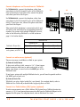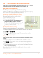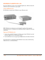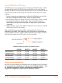
1
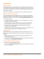
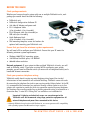
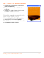
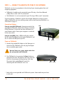
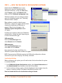
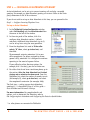
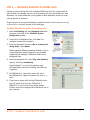
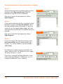
TA L K S W I TC H D O C U M E N TAT I O N
START GUIDE
RELEASE 3.24
C T.T S 0 0 5 . 0 0 2 5 0 1 . U K
ANSWERS WITH INTELLIGENCE
®
INTRODUCTION
About this guide
This guide describes the steps required to do basic installation and configuration of
your TalkSwitch telephone system. Once you have completed these steps, your system
can be further customized for your needs. For complete configuration details, refer to
the TalkSwitch User Guide.
This guide is intended for use with the UK versions of the TalkSwitch product line.
Where to go for further information
The guides listed below, and many other resources, can be found on the TalkSwitch
Configuration Software CD, in the TalkSwitch folder in the Windows Start menu once
the software has been installed, and online. Visit http://global.talkswitch.com and
select country or region.
• For complete configuration information, refer to the TalkSwitch User Guide after
completing the steps in this guide.
• For information on setting up a TalkSwitch system to use Voice-over-IP (VoIP),
refer to the TalkSwitch VoIP Configuration Guide for Multi-location Networks.
• For information on configuring your system remotely, refer to the Remote
Configuration over IP Quick Guide.
• For step-by-step instructions on specific features, refer to the Quick Guides in the
TalkSwitch Documentation folder in the Windows Start Menu.
Troubleshooting
The TalkSwitch system and the configuration software are designed for ease of use.
However, if you encounter difficulties with the installation or configuration of your
TalkSwitch:
• Consult the documents on the TalkSwitch Configuration Software CD or in the
•
TalkSwitch folder on your PC.
Access additional TalkSwitch information online, including FAQs, Quick Guides and
other resources at http://global.talkswitch.com.
Contacting TalkSwitch Technical Support
• Contact your authorized TalkSwitch reseller.
• Please refer to http://global.talkswitch.com for technical support, contact details
and hours of operation.
H T T P : / / G L O BA L . TA L K S W I TC H . C O M
1
BEFORE YOU BEGIN
Check package contents:
Whether you have purchased a system with one or multiple TalkSwitch units, each
package you receive should include the following:
•
•
•
•
•
•
•
TalkSwitch unit
TalkSwitch Configuration Software CD
220-240v AC Adapter and power cord
RJ-11 telephone cables
(4 for 48 models; 2 for 24 models)
RJ-45 Ethernet cable (for 48 models) or
USB cable (for 24 models)
Quick Reference Cards
(8 for 48 models; 4 for 24 models)
Wall mounting template, screws and anchors for
optional wall-mounting your TalkSwitch unit.
Ensure that you have the minimum system requirements
You will need a PC to configure your TalkSwitch. Ensure that your PC meets the
following minimum system requirements:
• Windows 2000/XP/98* operating system
• 120 MB free hard disk space, 128 MB RAM
• 800x600 video resolution
Network equipment: If your system includes multiple TalkSwitch 48 units, you will
need an Ethernet switch. If you plan on using VoIP or configuring your system
remotely, you will need an Ethernet switch (or router with an integrated switch) and a
broadband Internet connection.
Check your premises telephone wiring
TalkSwitch usually doesn’t require any extra telephone wiring beyond the standard
infrastructure in most commercial and residential buildings. TalkSwitch comes with cords
for connecting the telephone line jacks to your service provider’s Master Socket. In the UK,
it is recommended that extensions are connected through a Master Socket or an in-line
adapter with capacitor to provide the third wire connection required by many telephones.
For situations where service provider lines or building extension wiring is terminated on a
Connection Box, “3 metre RJ-11 Wiring Tails” are available as an installation kit.
Important! Lightning and electrical surges can cause damage to the
TalkSwitch unit. We recommend using surge protection equipment on all
external telephone and power lines connected to this device.
* Although TalkSwitch may function with Windows 98, we cannot guarantee full compatibility
with operating systems that Microsoft no longer supports.
2
TA L K S W I TC H S TA R T G U I D E • U K & I R E L A N D
STEP 1 — INSTALL THE TALKSWITCH SOFTWARE
1. Ensure that you have Administrator privileges on your
Windows XP or 2000 system.
2. Turn your computer on, and insert the CD into the
CD-ROM drive.
3. The Install main window will appear within 20 seconds.
Click INSTALL and follow the instructions.
If the installation program does not automatically start (for
example, if Autorun is disabled on your PC):
1. From the desktop, double-click the My Computer icon.
2. Double-click on the CD drive labeled TalkSwitch.
3. Double-click on startscreen.exe located in the start folder.
4. Click Install and follow the instructions.
H T T P : / / G L O BA L . TA L K S W I TC H . C O M
3
STEP 2 — CONNECT TALKSWITCH TO YOUR PC OR NETWORK
TalkSwitch can be set up anywhere in the vicinity of your incoming phone lines and
computing equipment.
• TalkSwitch 48 models can be connected to your PC using a Local Area Network
•
(LAN), USB, or serial* (RS-232) connection.
The TalkSwitch 24 can be connected to your PC using a USB or serial* connection.
If you’re installing a TalkSwitch system with multiple TalkSwitch 48 units or you’re
adding a TalkSwitch unit to an existing system, refer to the Networking TalkSwitch on a
LAN section on page 12.
Connection Options
Connect using LAN (Ethernet): Connect one end of the
provided RJ-45 Ethernet cable to the LAN port at the back
of the TalkSwitch 48 unit and the other end directly to
your Ethernet switch. Ensure your computer is connected
to the same switch.
LAN
Connect using USB: Using a USB A-to-B cable, connect
the “B” end to the USB port at the back of TalkSwitch, and
the “A” end to the USB port of your PC.
USB
Power
Power up TalkSwitch
1. Connect the provided AC Adapter to the Power port at
the back of the TalkSwitch unit and plug the adapter
into an available power outlet.
Warning! Never use a power adapter other than
the one provided with TalkSwitch.
2. Turn TalkSwitch on by pressing the Power button on
the front of the unit. The lights on the front panel will
flash for a few moments during boot-up, then stop.
The center light marked Data will remain lit,
indicating that the TalkSwitch unit is on.
Data
Power
* Serial cables are not provided with TalkSwitch systems. Some models may not have
a serial port.
4
TA L K S W I TC H S TA R T G U I D E • U K & I R E L A N D
STEP 3 — OPEN THE TALKSWITCH CONFIGURATION SOFTWARE
Double-click the TalkSwitch icon on your
Desktop (this icon was created during the
software installation), or from the Start menu,
select Programs, select the TalkSwitch 3.24
folder, and click TalkSwitch Configuration 3.24.
TalkSwitch Software will now attempt to detect
your unit, displaying progress on a “Detecting
TalkSwitch Units” window.
When software succeeds in detecting your
TalkSwitch, a progress bar appears on the screen
showing the connection to TalkSwitch in
progress. When the bar disappears, the
TalkSwitch System Configuration window
will appear.
If software was unable to detect your TalkSwitch
automatically, a dialog box opens requesting you
to select the connection type.
LAN connection:
From the Connection Type menu,
select Ethernet and click Connect.
USB connection:
From the Connection Type menu,
select USB and click Connect.
Once connection has been established, the
TalkSwitch System Configuration window will appear.
NOTE: If you encounter difficulties opening the TalkSwitch configuration software,
check that all your wires and plugs are securely connected.
Localization Setting
Before configuring your system, you will need to select the location where the system
is currently installed:
1. In the TalkSwitch System Configuration window, select System Information and
then Administration from the menu at the left of the window.
2. In the Localization Settings section, click the dropdown list box to select where the
system is currently installed. The default International location is UK.
Users in Ireland should set the localization setting to Ireland.
H T T P : / / G L O BA L . TA L K S W I TC H . C O M
5
STEP 4 — CONFIGURE AN AUTOMATED ATTENDANT
An Auto Attendants can be set up to answer incoming calls and play a recorded
greeting. For example, an Auto Attendant greeting can instruct callers to dial their
party’s extension or dial ‘0’ for assistance.
If you do not wish to set up an Auto Attendant at this time, you can proceed to the
Step 5 — Configure Incoming Telephone Lines.
Set up an Auto Attendant
1. In the TalkSwitch System Configuration window,
select Call Handling and then Auto Attendant from
the menu at the left of the window.
2. In the main panel of the window, click 1 to
configure Auto Attendant number 1 (default
selection). Additional Auto Attendants (up to 9)
can be set up later using the same procedure.
X
3. From the drop-down lists next to If the caller
selects “0” then:, select go to local ext., and
then 114.
We recommend assigning extension 114 to your
office receptionist (or person assigned to answer
general calls); extension 114 is designed to continue
operating in the event of a power failure.
If your office has other directory options (for
example, dial 1 for sales), you can set these now.
4. For callers that do not have a touchtone phone, go to
the section: After the Auto Attendant has finished
playing and no selection has been made. From the
drop-down lists select the number of seconds to wait
(for example, 5), select go to local ext., and select
the receptionist's extension (for example, 114).
Y
Z
[
The final step — setting up your Auto Attendant
greeting(s) — is described in Step 8* of this guide —
Auto Attendant and Voicemail Greetings.
For more information: For complete details and
options, such as Automatic Fax Detection, refer to
the Configuring Auto Attendants and Configuring Fax Detection Quick Guides.
* i.e. after phones are connected to TalkSwitch
6
TA L K S W I TC H S TA R T G U I D E • U K & I R E L A N D
STEP 5 — CONFIGURE INCOMING TELEPHONE LINES
Setting up your incoming lines will customize TalkSwitch to fit the unique needs of
your business. For example, you can set all incoming calls to be answered by an Auto
Attendant, set certain extensions to ring before an Auto Attendant answers, or have
calls go directly to voicemail.
If you have not set up an Auto Attendant, proceed to the Set certain extensions to ring
or direct calls to voicemail section on the next page.
Set Auto Attendant to answer all incoming calls
1. Select Call Handling and then Telephone Lines from
the menu on the left of the TalkSwitch System
Configuration window.
2. From the list of telephone lines, click Line 1 to
configure incoming line number 1.
X
3. From the drop-down list next to On an incoming call
during mode:, select Mode 1.
Modes represent different operating schedules, such as
standard business operating hours or non-standard
(weekends and evenings). Additional modes can be
configured later.
4. From the drop-down lists, select Play auto attendant,
select 1, and select immediately.
Auto Attendant 1 (set up in the previous step)
will immediately answer all incoming calls and play
a greeting.
Y
Z
[
5. For TalkSwitch 24, repeat this process for Line 2.
For TalkSwitch 48, repeat this process for Lines 2, 3,
and 4.
6. If you have a system with multiple TalkSwitch units,
you will notice up to four tabs (TalkSwitch 1,
TalkSwitch 2, etc.) across the top of the window.
Click on each tab to configure each TalkSwitch unit in
your network.
H T T P : / / G L O BA L . TA L K S W I TC H . C O M
7
Set certain extensions to ring or direct calls to voicemail
Option 1
To have certain extensions ring without playing an Auto
Attendant, select Ring extensions only. Select the
extensions to ring from the list of extensions.
Option 1
Note: you can adjust the ring sequence by clicking
Adjust Sequence.
Option 2
To have certain extensions ring for a time before the Auto
Attendant is played, select Play auto attendant. Select
the Auto Attendant number (for example, 1), select the
number of rings (for example, after 3 rings), and select
the extensions to ring from the list (by default they are all
selected).
Option 2
Note: you can adjust the ring sequence by clicking
Adjust Sequence.
Option 3
To have all incoming calls directed to voicemail, select
Go to voice mailbox, select the mailbox number (for
example, 111), and the number of rings (for example,
after 3 rings).
For TalkSwitch 24, repeat the process described in the
options above for Line 2. For TalkSwitch 48 units, repeat
the process for Lines 2, 3, and 4.
Option 3
If you have a system with multiple TalkSwitch 48 units,
click on each tab (TalkSwitch 1, TalkSwitch 2, etc.) to
configure all TalkSwitch units in a network.
8
TA L K S W I TC H S TA R T G U I D E • U K & I R E L A N D
STEP 6 — SAVE SETTINGS TO TALKSWITCH
This step will transfer the settings you have configured from your
computer to the TalkSwitch system.
From the File menu in the TalkSwitch System Configuration
window, select Save to TalkSwitch... A progress bar appears
indicating that the configuration information is being sent to the
TalkSwitch system.
STEP 7 — CONNECT TELEPHONES AND PERIPHERALS
Connect incoming (external) telephone lines
Important! Lightning and electrical surges can cause damage to
TalkSwitch. We recommend using surge protection equipment on all
external telephone and power lines connected to a TalkSwitch system.
Single line connection (1 incoming phone line per wall phone jack)
Two-wire connector
Use the RJ-11 telephone cables provided to connect external
phone lines to TalkSwitch. These cables have a two-wire
connector for connection to a single line wall jack. Do not
use four-wire telephone cables. See “Check your premises
telephone wiring” for notes on telephone line and extension
wiring. Users in Ireland should use 2-wire RJ-11 to RJ-11
telephone cords.
1. Connect one end of the provided RJ-11 telephone cable
to the wall phone jack of an incoming phone line and
the other end to the L1/L2 port at the back of the
TalkSwitch unit.
48
24
L3/L4
L4
L1/L2
L2
2. If necessary, connect a second external phone line to
the L2 port of the TalkSwitch unit using the
same method.
3. If you have a TalkSwitch 48, connect the remaining
external phone lines to the L3/L4 and L4 ports at the
back of the TalkSwitch unit, respectively.
L1/L2
H T T P : / / G L O BA L . TA L K S W I TC H . C O M
L2
9
Connect telephones and fax machines to TalkSwitch
For TalkSwitch 24, connect the telephone cables from
your phones to the E1 through E4 ports of the TalkSwitch
unit, consecutively. If you have a fax, connect the phone
cable from your fax to the E3 port.
48
24
E5 E6 E7 E8
For TalkSwitch 48, connect the telephone cables from
your phones to the E1 through E8 ports of the TalkSwitch
unit(s). If you have a fax, connect the phone cable from
your fax to the E8 port.
Take note of which telephone is connected to which port
and refer to the table below for corresponding extension
numbers. For systems with multiple TalkSwitch 48 units,
refer to the Networking TalkSwitch on a LAN section on
page 12 for further details.
E1 E2 E3 E4
E1 E2 E3 E4
TalkSwitch 48
TalkSwitch 24
TalkSwitch Phone Port
E1
E2
E3
E4
E5
E6
E7
E8
Extension number (single
unit systems; unit ID = 1)
111
112
113
114
115
116
117
118
Connect an audio source (optional)
There are two ways to add Music on Hold to your system.
A) External Audio Source
To play music while on hold, connect a 1/8" (3.5mm) mono
phono connector cable from an audio source such as a CD
player, tape player, or sound card to the MUSIC port of the
TalkSwitch unit.
MUSIC
If you have a system with multiple TalkSwitch units, you will need to provide audio to
the MUSIC ports of each unit.
B) Internal Music File
TalkSwitch can play a digital audio file (.wav format). For complete details, refer to
TalkSwitch User Guide and/or Quick Guide Configuring Music on Hold.
Connect to a Public Address (PA) System (optional)
To make announcements over a Public Address (PA) System from a TalkSwitch extension,
connect a 1/8" (3.5mm) mono phone connector cable from the TalkSwitch PA port to the
input of the PA system. For complete details, refer to TalkSwitch User Guide.
10
TA L K S W I TC H S TA R T G U I D E • U K & I R E L A N D
STEP 8 — AUTO ATTENDANT AND VOICEMAIL GREETINGS
If you have set up an Auto Attendant, as described in Step 4 of this guide — Configure
an Automated Attendant, then you should load or record a greeting now.
What should an Auto Attendant say?
The following is an example of a typical Auto Attendant greeting:
"Welcome to the ABC company. If you know your party's three-digit extension you may
dial it now. To reach reception, press '0' or stay on the line."
To load a pre-recorded Auto Attendant greeting
You can load a professionally pre-recorded greeting to
TalkSwitch by following these steps:
1. Click on Load Auto Attendant..
2. An information box opens asking whether or not to
continue. Click Yes and follow the instructions.
The file must be an 8khz, 8-bit, mono, µ-law .wav file.
A sample greeting (Auto Attendant Sample.wav) is
provided in your TalkSwitch folder.
Record an Auto Attendant greeting
X
To record an Auto Attendant greeting for Auto Attendant 1:
1. Pick up any telephone connected to the TalkSwitch. You should hear a dial tone.
2. Press #
then
#
4
#1
#
3. Follow the prompts to record your message. When your greeting is complete,
press # to end the recording.
Set up and record voicemail
To set a password, record a personal greeting, and record your name for the company
directory:
1. Pick up any telephone connected to TalkSwitch. You should hear a dial tone.
2. Dial #4
* #*1 and your mailbox number. Your mailbox number is equivalent to
your extension number.
3. Follow the prompts to set a password, record a personal greeting, and record your
name for the company directory.
For complete details, refer to Quick Guide Configuring Auto Attendants, and/or
TalkSwitch User Guide.
H T T P : / / G L O BA L . TA L K S W I TC H . C O M
11
NETWORKING TALKSWITCH ON A LAN
Up to four TalkSwitch 48 units can be networked together over a LAN to increase the
number of lines and extensions in your system.
Connect TalkSwitch units
Use LAN cables to connect each TalkSwitch to your Ethernet switch.
NOTE: TalkSwitch unit enclosures are not designed for stacking. We recommend
wall-mounting units in a horizontal row to maximize airflow and keep the units from
overheating.
Power up all TalkSwitch units
1. Connect the provided AC Adapters to the Power ports of each TalkSwitch unit and
plug each adapter into an available power outlet.
2. Turn the TalkSwitch units on by pressing the Power button on the front of each unit.
For further details on networking multiple TalkSwitch units, refer to the Networking
TalkSwitch Units on a LAN Quick Guide.
12
TA L K S W I TC H S TA R T G U I D E • U K & I R E L A N D
Changing TalkSwitch unit ID numbers
Each TalkSwitch unit is pre-programmed at the factory with Unit ID number 1. When
you plug multiple units in for the first time or add a unit or units to an existing
network, the lights on the front of each TalkSwitch flash. This is an indication that all
units have the same ID number. Change the ID numbers so that they are all unique,
as follows:
1. Connect a phone to any extension port (eg. E4) of the TalkSwitch unit for which
you want to change the unit ID number, and lift the phone handset.
2. The TalkSwitch prompt will indicate that there is an ID conflict. Choose a number,
for example “2”, as the new unit ID number. Once the unit ID number has
been accepted, the lights on the front panel will stop flashing (usually within
10 seconds).
3. Repeat the above steps for each additional TalkSwitch unit, assigning a unique ID
number to each unit on the network.
After successfully changing each unit ID to a unique number, each unit can be
identified by the network. More importantly each local extension, remote extension,
and voice mailbox, will have a unique number wherein the second digit in the three
digit identifier becomes the unit ID number. See the table below.
TalkSwitch Numbering Scheme for Networked Units
Unit ID 1
Unit ID 2
Unit ID 3
Unit ID 4
Local Extensions
111-118
121-128
131-138
141-148
Remote Extensions
211-218
221-228
231-238
241-248
Local Mailboxes
111-118
121-128
131-138
141-148
Remote Mailboxes
211-218
221-228
231-238
241-248
General Mailboxes
410-419
420-429
430-439
440-449
Configuring the Networked Units
Now that you have connected your TalkSwitch units and changed the unit ID numbers,
you can configure call handling options for the new unit(s). Return to Step 3 — Open
the TalkSwitch Configuration Software and follow the subsequent steps to
complete the configuration of your expanded TalkSwitch network.
H T T P : / / G L O BA L . TA L K S W I TC H . C O M
13
SETUP COMPLETE
Congratulations!
Your TalkSwitch system should now be ready to accept incoming calls.
TIP: Put a TalkSwitch Quick Reference Card next to each extension phone, to help
employees become familiar with the TalkSwitch features.
Configuring TalkSwitch 48 remotely
Once installation is complete, you can configure your TalkSwitch 48 via a TCP/IP
connection between TalkSwitch and a remote PC running the TalkSwitch configuration
software. For details, refer to the TalkSwitch Remote Configuration over IP Quick Guide.
Note: If TalkSwitch is installed behind a router/firewall, you will need to map port
9393 to TalkSwitch to enable remote configuration (for details on port mapping, visit
http://www.portforward.com/routers.htm).
What next
• For advanced configuration and complete information on TalkSwitch features, refer
•
•
to the TalkSwitch User Guide.
To add remote extensions to your TalkSwitch system, refer to the Configuring
Remote Extensions Quick Guide.
To configure your TalkSwitch 48 system to use VoIP, refer to the TalkSwitch VoIP
Configuration Guide for Multi-location Networks.
We trust that your TalkSwitch phone system will provide exceptional features,
performance and value to your business. Should you have any further questions, please
contact your authorized TalkSwitch reseller or visit http://global.talkswitch.com and
select country or region.
We welcome your feedback, comments and suggestions. Please e-mail us at
[email protected] or write us at TalkSwitch, 1545 Carling Avenue, Suite 510,
Ottawa, ON Canada K1Z 8P9.
Thank you for choosing TalkSwitch.
14
TA L K S W I TC H S TA R T G U I D E • U K & I R E L A N D
TalkSwitch. Copyright 2006.
All Rights Reserved.
CT.TS005.002501.UK (April 2006)
TalkSwitch is a division of Centrepoint Technologies Inc.