1
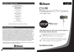
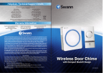
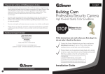
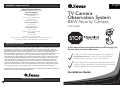
English
Help Desk / Support Details
Swann Technical Support
All Countries E-mail: [email protected]
Telephone Helpdesk
UNITED STATES toll free
877-274-3695
(Sun-Thurs, 2pm-10.30pm PST)
800-627-2799
(Mon0Fri, 9am-1pm PST)
USA Exchange & Repairs
562-777-2551
(Mon-Fri, 9am-5pm PST)
AUSTRALIA toll free
1300 13 8324
(Mon-Fri, 9am-5.30pm Aus EST)
International
+61 3 8412 4610
(Mon-Fri, 9am-5.30pm Aus EST)
See http://www.worldtimeserver.com for information on different time zones
and the time in Melbourne Australia compare to your local time.
TV Camera
Observation System
B&W Security Camera
with Audio
Warranty Information
Swann Communications warrants this product against defects in workmanship and material for
a period of one (1) year from it’s original purchase date. You must present your receipt as
proof of date of purchase for warranty validation. Any unit which proves defective during the
stated period will be repaired without charge for parts or labour or replaced at the sole
discretion of Swann. The repair or replacement will be warranted for either ninety days or the
remainder of the original one year warranty period, whichever is longer. The end user is
responsible for all freight charges incurred to send the product to Swann’s repair centres. The
end user is responsible for all shipping costs incurred when shipping from and to any country
other than the country of origin. The warranty does not cover any incidental, accidental or
consequential damages arising from the use of or the inability to use this product. Any costs
associated with the fitting or removal of this product by a tradesman or other person or any
other costs associated with its use are the responsibility of the end user. This warranty applies
to the original purchaser of the product only and is not transferrable to any third party.
If this device does not work when you first plug it in,
do not take it back to the store.
Contact the Swann Helpdesk using our fast e-mail service
[email protected] or call us on one of the Toll-Free
numbers shown on the back cover of this booklet.
Most problems can be quickly and easily fixed with a simple
e-mail or a quick chat with one of our friendly technical staff.
(Toll-Free available in the US and Australia only)
Unauthorised end user or third party modifications to any component or evidence of misuse or
abuse of the device will render all warranties void.
Installation Guide
www.swannsecurity.com
4
Installation Instructions
How to connect TV Camera Observation System to your TV or VCR
The TV Camera Observation System is designed for use with any AV TV, VCR, Security Monitor
or computer with a video capture card. The camera has a built-in microphone to offer sound as
well as a visual image and can be used indoors or in a sheltered position outside. The TV Camera
Observation System can be used for a variety of purposes including monitoring callers at the
door, keeping your car, yard, shop or warehouse under observation or used as a camera to
monitor your baby.
Step 1: At the end of your TV Camera Observation System cable you will find three colored plugs:
•Yellow (Video RCA)
•Red (Audio RCA)
•Black
Step 2: Plug the yellow RCA plug (1) into the "Video In" input (3) (usually located at the back of your
TV or VCR).
Step 3: Plug the Red RCA plug (2) into the "Audio In" input (4) (usually located at the back of your
TV or VCR).
Contents and Parts Identification
Step 4: Connect the black plug (5) at the end of your TV Camera Observation System into the black
plug at the end of the power adaptor (6).
1. Camera with Stand and 18m/60ft cable
2. 9Volt DC 300mA Power Adaptor (adaptor design varies depending on country)
Step 5: Plug the power adaptor (6) into the mains power point in your wall.
1
2
Step 6: If you have an A/V TV with RCA sockets you will need to switch the TV to the AV channel
on your TV to view the camera. To connect the camera to your VCR, you will need to turn
the VCR to the A/V Input selection and turn your TV onto the channel you would normally
use to view a tape or movie on your VCR. This channel may be activated by a button on your
remote that is marked with this symbol
, or L1 or L2 or possibly AV1 or AV2.
Note:
Please read the instructions for your VCR or TV for more information on using their
A/V inputs.
Step 7: If the picture is not clear, you will need to undo the small grub screw that locks the lens in
place, which is located underneath the barrel that the lens screws in to. Focus the camera by
turning the lens in a clockwise or anti-clockwise direction until the image is clear, then retighten the small grub screw.
How to connect TV Camera Observation System to your TV or VCR
Your TV Camera Observation System is designed to transmit high quality Color images and sound
to your television and is operated by mains power. To help guide you through the process of
setting up the TV Camera Observation System, we have outlined the steps and numbered each of
the components required in the diagram below.
Mounting the camera on your wall or ceiling
1.
2.
CAMERA
VCR, TV or MONITOR
6
Red
OUT
IN
VIDEO IN 3
2
VIDEO AUDIO
POWER
ADAPTOR
5 BLACK
4.
VIDEO AUDIO
4
1 YELLOW
AUDIO IN
* To extend the operating distance from your TV or VCR you will need to purchase an A/V extension cable
(sold separately) which are available at most electronics stores. See the back page for accessary product codes.
2
3.
5.
Once you have chosen the best position for the camera, switch the
power to the camera off, and unplug the power lead from the
camera.
When mounting the TV Camera Observation System to your ceiling
or wall, please ensure that you rotate the camera so that the small
hole (microphone) at the top of the camera lens is ‘up’, otherwise
microphone
you will find that your pictures are displayed upside down. (see
diagram)
Hold the camera base in the position you wish to fix it, and mark the
holes with an appropriate pen or pencil. Once this is done, remove
the stand and drill a hole with the appropriate drill bit for the material
you are mounting your camera to and the screws you are using.
Run the camera cable back to the TV/VCR, any holes that you drill
need to be at least 14mm in diameter to allow the connectors to
pass through.
Reconnect the power lead to the camera and switch the camera
power back on.
3