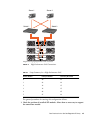
1
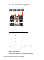
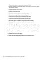
Sun StorEdge™ 3000 Family Best Practices Manual Sun StorEdge 3510 FC Array Sun Microsystems, Inc. www.sun.com Part No. 816-7325-12 October 2003, Revision A Submit comments about this document at: http://www.sun.com/hwdocs/feedback Copyright © 2003 Dot Hill Systems Corporation, 6305 El Camino Real, Carlsbad, California 92009, USA. All rights reserved. Sun Microsystems, Inc. and Dot Hill Systems Corporation may have intellectual property rights relating to technology embodied in this product or document. In particular, and without limitation, these intellectual property rights may include one or more of the U.S. patents listed at http://www.sun.com/patents and one or more additional patents or pending patent applications in the U.S. and other countries. This product or document is distributed under licenses restricting its use, copying distribution, and decompilation. No part of this product or document may be reproduced in any form by any means without prior written authorization of Sun and its licensors, if any. Third-party software is copyrighted and licensed from Sun suppliers. Parts of the product may be derived from Berkeley BSD systems, licensed from the University of California. UNIX is a registered trademark in the U.S. and in other countries, exclusively licensed through X/Open Company, Ltd. Sun, Sun Microsystems, the Sun logo, Sun StorEdge, AnswerBook2, docs.sun.com, and Solaris are trademarks or registered trademarks of Sun Microsystems, Inc. in the U.S. and in other countries. U.S. Government Rights—Commercial use. Government users are subject to the Sun Microsystems, Inc. standard license agreement and applicable provisions of the FAR and its supplements. DOCUMENTATION IS PROVIDED “AS IS” AND ALL EXPRESS OR IMPLIED CONDITIONS, REPRESENTATIONS AND WARRANTIES, INCLUDING ANY IMPLIED WARRANTY OF MERCHANTABILITY, FITNESS FOR A PARTICULAR PURPOSE OR NONINFRINGEMENT, ARE DISCLAIMED, EXCEPT TO THE EXTENT THAT SUCH DISCLAIMERS ARE HELD TO BE LEGALLY INVALID. Copyright © 2003 Dot Hill Systems Corporation, 6305 El Camino Real, Carlsbad, Californie 92009, Etats-Unis. Tous droits réservés. Sun Microsystems, Inc. et Dot Hill Systems Corporation peuvent avoir les droits de propriété intellectuels relatants à la technologie incorporée dans le produit qui est décrit dans ce document. En particulier, et sans la limitation, ces droits de propriété intellectuels peuvent inclure un ou plus des brevets américains énumérés à http://www.sun.com/patents et un ou les brevets plus supplémentaires ou les applications de brevet en attente dans les Etats-Unis et dans les autres pays. Ce produit ou document est protégé par un copyright et distribué avec des licences qui en restreignent l’utilisation, la copie, la distribution, et la décompilation. Aucune partie de ce produit ou document ne peut être reproduite sous aucune forme, par quelque moyen que ce soit, sans l'autorisation préalable et écrite de Sun et de ses bailleurs de licence, s’il y ena. Le logiciel détenu par des tiers, et qui comprend la technologie relative aux polices de caractères, est protégé par un copyright et licencié par des fournisseurs de Sun. Des parties de ce produit pourront être dérivées des systèmes Berkeley BSD licenciés par l’Université de Californie. UNIX est une marque déposée aux Etats-Unis et dans d’autres pays et licenciée exclusivement par X/Open Company, Ltd. Sun, Sun Microsystems, le logo Sun, Sun StorEdge, AnswerBook2, docs.sun.com, et Solaris sont des marques de fabrique ou des marques déposées de Sun Microsystems, Inc. aux Etats-Unis et dans d’autres pays. LA DOCUMENTATION EST FOURNIE “EN L’ÉTAT” ET TOUTES AUTRES CONDITIONS, DECLARATIONS ET GARANTIES EXPRESSES OU TACITES SONT FORMELLEMENT EXCLUES, DANS LA MESURE AUTORISEE PAR LA LOI APPLICABLE, Y COMPRIS NOTAMMENT TOUTE GARANTIE IMPLICITE RELATIVE A LA QUALITE MARCHANDE, A L'APTITUDE A UNE UTILISATION PARTICULIERE OU A L’ABSENCE DE CONTREFAÇON. Please Recycle Contents Overview 1 Introduction Overview 2 3 Fibre Channel Architecture Fibre Channel Protocols 3 Supported RAID Levels 4 Logical Drives 3 4 Cache Optimization 5 Array Management Tools 6 Saving and Restoring Configuration Information Direct-Attached Storage Storage Area Networking Scaling Capacity First Steps 7 7 8 9 10 General Configuration Considerations Non-Redundant DAS Configurations 11 12 Non-Redundant DAS Tips and Techniques Non-Redundant DAS Setup Details High-Availability DAS Configurations 13 14 15 iii High-Availability DAS Tips and Techniques High-Availability DAS Setup Details Full-Fabric SAN Configurations 17 19 Full-Fabric SAN Tips and Techniques Full-Fabric SAN Setup Details 20 20 High-Performance SAN Configurations 23 High-Performance SAN Tips and Techniques High-Performance SAN Setup Details Summary iv 16 26 Sun StorEdge 3000 Family Best Practices Manual • October 2003 24 24 Best Practices for the Sun StorEdge 3510 FC Array This document highlights Fibre Channel (FC) best practices which apply to the Sun StorEdge 3510 FC array. Overview The Sun StorEdge 3510 array is a next generation Fibre Channel storage system designed to provide direct attached storage (DAS) to entry-level, mid-range, and enterprise servers, or to serve as the disk storage within a storage area network (SAN). This solution features powerful performance and reliability, availability and serviceability (RAS) features using modern FC technology. As a result, the Sun StorEdge 3510 FC array is ideal for performance sensitive applications and for environments with many entry-level, mid-range, and enterprise servers, such as: ■ Internet ■ Messaging ■ Database ■ Technical ■ Imaging This document gives a high level overview of the Sun StorEdge 3510 FC array and outlines four sample storage solutions for entry-level, mid-range, and enterprise servers. The Sun StorEdge 3510 FC array supports multiple servers, so these solutions are designed to match the overall environment rather than the particular applications running within it. Use them as-is or tailor them to fit your exact needs. Examples of customization opportunities include adding disks, enclosures and software or even combining configurations. Choosing the solution that best matches each particular environment will provide the best results. 1 Introduction There are two popular methods for connecting storage to servers. ■ The original and still most widely used approach uses a direct connection between a server and its storage system. A storage system connected in this manner is commonly referred to as direct-attached storage (DAS). The DAS solution of connecting each server to its own dedicated storage system is straightforward, and the absence of storage switches can minimize costs in some instances. ■ A newer, more sophisticated technique places a storage switch between network servers and storage systems, creating what has become known as a Storage Area Network (SAN). In many ways, these two methods create contrasting storage architectures providing their own unique mix of benefits. A SAN solution shares a storage system among multiple servers using storage switches, and reduces the total number of storage systems required for a particular environment but increases the complexity. Direct-Attached Storage (DAS) Storage Area Network (SAN) FIGURE 1 DAS and SAN Storage Architectures Selecting the best storage architecture for a particular environment can be a confusing exercise. In general, some environments are well-suited for DAS while others will benefit greatly from SAN. The challenge of selecting between DAS and SAN is often further complicated by the need to choose between different storage systems – one designed for DAS or another intended for SAN. Fortunately, every Sun StorEdge 3510 FC array inherently supports both DAS and SAN. 2 Sun StorEdge 3000 Family Best Practices Manual • October 2003 Overview Fibre Channel Architecture The Sun StorEdge 3510 FC array RAID controller has six fibre channels that can support 1 or 2 Gb data transfer speeds. RAID controller channels 0, 1, 4, and 5 are normally designated for connection to hosts or Fibre Channel switches. RAID controller channels 2 and 3 are dedicated drive channels. In a dual RAID controller configuration, both RAID controllers have the same host channel designators, due to the architecture of the loops within the chassis. Each host channel of the top RAID controller shares a loop with the matching host channel on the bottom RAID controller. For example, channel 0 of the top RAID controller shares the same loop as channel 0 of the bottom RAID controller. This provides four distinct loops for connectivity with two ports per loop. The individual loops provide LUN failover without causing HBA path failover in the event of a controller failure. Each I/O board has two ports designated as disk drive loops. These ports connect to the internal dual-ported Fibre Channel disk drives and are used to add expansion chassis to the configuration. The two drive loop ports on the upper I/O board form FC loop 2 while the two drive ports on the lower I/O board form FC loop 3. FC loop 2 provides a data path from both RAID controllers to the A loop of the internal disk drives, while FC loop 3 provides a data path from both RAID controllers to the B loop of the internal disk drives. A single RAID controller configuration is slightly different. The lower I/O board has drive channels but does not have host channels. Overall, the same number of loops are available, but with half as many host channel ports. Fibre Channel Protocols The Sun StorEdge 3510 FC array supports point-to-point and Fibre Channel– Arbitrated Loops (FC–AL) protocols. Using the point-to-point protocol with the Sun StorEdge 3510 FC array requires a switched fabric network (SAN), whereas selecting FC-AL mode enables the array to be used in either DAS or SAN environments. Using point-to-point protocol enables full-duplex use of the available channel bandwidth, whereas selecting FC-AL mode limits host channels to half-duplex mode. Best Practices for the Sun StorEdge 3510 FC Array 3 In a point-to-point configuration, only one ID can be assigned to each host channel. If more than one ID is assigned, the point-to-point protocol rules are violated. Any host channel with more than one ID will not be able to log in to an FC switch in fabric mode. This “one-ID-per-channel” requirement is true in both single-controller and dual- controller configurations. Thus, in dual-controller configurations, either the primary or the secondary controller can have an ID assigned, but not both. This yields: (4 host channels) X (1 ID per channel) X (32 LUNs per ID) = 128 maximum addressable LUNs in a fabric point-to-point environment. If dual paths are desired for each logical device, a maximum of 64 dual-pathed LUNs are available. In an FC-AL configuration, multiple IDs can be assigned to any given host channel. Although it is possible to add more, it is preferable that no more than four IDs be assigned to a controller on a given host channel. Thus no more that eight IDs should be assigned to any host channel if both primary and secondary controllers each have four IDs. This yields (4 host channels) X (8 IDs per channel) X (32 LUNs per ID) = 1024 maximum addressable LUNs in a FC-AL environment. However, configuring the maximum number of LUNs increases overhead and can have a negative impact on performance. The FC-AL protocol should be selected for environments needing more than 128 LUNs, or where a switched fabric network is not available. Supported RAID Levels There are several RAID level choices: RAID 0, 1, 3, 5, 1+0 (10), 3+0 (30), and 5+0 (50). RAID levels 1, 3, and 5 are the most commonly used. The Sun StorEdge 3510 FC array supports the use of both global and local spare drives in the unlikely event of disk failure. It is good practice to use spare drives when configuring RAID devices. Refer to the Sun StorEdge 3000 Family RAID Firmware 3.27 User’s Guide, Sun StorEdge 3510 FC Array (P/N 816-7934) for detailed information on how RAID levels and spare drives are implemented. Logical Drives A logical drive (LD) is a group of physical drives configured with a RAID level. Each LD can be configured for a different RAID level. The Sun StorEdge 3510 FC array supports a maximum of eight LDs. A LD can be managed by either the primary or secondary controller. The best practice for creating LDs is to split them evenly across the primary and secondary controllers. The most efficient maximum configuration would have four LDs assigned to each controller. 4 Sun StorEdge 3000 Family Best Practices Manual • October 2003 With at least one LD assigned to each controller, both controllers are active. This configuration is known as an active-active controller configuration and allows maximum use of a dual controller array's resources. Each LD can be partitioned in up to 128 separate partitions or used as a single partition. The partitions are presented to the host as LUNs. Once the LDs have been created, assigned to a controller, and partitioned, the partitions must be mapped to host channels as LUNs in order for them to be seen by a host. It is usually desirable to map each partition to two host channels for redundant pathing. A partition can only be mapped to a host channel where its controller has an assigned ID. For example, if LD 0 is assigned to the primary controller, all partitions on LD 0 will need to be mapped to a host channel ID on the primary controller (PID). Any LDs assigned to the secondary controller will need to have all partitions mapped to a host channel ID on the secondary controller (SID). When attaching fibre cables for LUNs configured with redundant paths, make sure one cable is connected to an upper port channel and the other cable is connected to a different channel on the lower controller. Then, if multipathing software is configured on the host, a controller can be hot-swapped in the event of failure without losing access to the LUN. For example, suppose partition 0 of LD0 is mapped to Channel 0 PID 42 and Channel 5 PID 47. To ensure that there is no single point of failure (SPOF), connect a cable from the host HBA or a switch port to the upper board port FC0, and connect a second cable from the lower board port FC5 to a different host HBA or switch. Cache Optimization The Sun StorEdge 3510 FC array can optimize the RAID devices for either sequential I/O or random I/O. Sequential I/O is the default setting. The sequential optimization mode reads and writes data in large 128K blocks, in order to transfer information more efficiently for the kinds of applications most often employed. The logical drive, cache memory, and other controller internal parameters are adjusted for high throughput use such as video and imaging applications. The maximum allowable size of a logical drive optimized for sequential I/O is 2 terabytes (TB). The random I/O optimization mode reads and writes data in small 32K blocks. When using random I/O optimization mode, the logical drive, cache memory, and other controller parameters are adjusted for the use of database/transactionprocessing applications. The maximum allowable size of a logical drive optimized for random I/O is 512 GB. This limit constrains the number of disks that can be included in a logical drive. Best Practices for the Sun StorEdge 3510 FC Array 5 Numerous controller parameters are also changed to optimize for sequential or random I/O. The change takes effect after the controller resets. Sequential or random optimization must be set prior to creating logical drives. There are two limitations that apply to the optimization modes. ■ One optimization mode must be applied to all logical drives in a RAID array. ■ Once the optimization mode is selected and logical drives are created, the optimization mode of those logical drives cannot be changed. The only way to change the optimization mode is to delete all logical drives, select the new optimization mode, reboot the array, and create new logical drives. Any existing data on the logical drives is lost during this procedure, which is why it is important to correctly select the optimization mode early in the planning process. Array Management Tools The Sun StorEdge 3510 FC array can be configured and monitored through any of the following methods: ■ Using the out-of-band serial port connection, a Solaris tip session or terminal emulation program for other supported operating systems can be used to access the Sun StorEdge 3510 FC array's internal firmware application. All procedures can be performed by using the firmware’s terminal interface via the COM port. ■ In-band configuration options from a host system include the Sun StorEdge Configuration Service software or the command-line interface (CLI). Refer to the Sun StorEdge 3000 Family Configuration Service User's Guide (P/N 816-7931) for information about how to set up and use of the Configuration Service software package. The CLI is installed as part of the SUNWsccli package. The main advantages of the CLI are that commands can be scripted and information can be passed to other programs. Information on CLI functionality can be found in the sccli man page once the package is installed. ■ Using the out-of-band Ethernet port connection, telnet can be used to access the firmware application. All procedures except the initial assignment of an IP address can be done through an Ethernet port connection. Refer to the Sun StorEdge 3000 Family Installation, Operation and Service Manual for the Sun StorEdge 3510 FC Array (P/N 816-7300) and the Sun StorEdge 3000 Family Configuration Service User's Guide (P/N 816-7931) for detailed information about using out-ofband management tools. Caution – If you assign an IP address to an array in order to manage it out-of-band, for security reasons make sure that the IP address is on a private network, rather than a publicly routable network. There are two main reasons for placing your arrays on a private subnet: 6 Sun StorEdge 3000 Family Best Practices Manual • October 2003 ■ When your array is on a public network, it is susceptible to viruses, worms, and other malware attacks. ■ A variety of security software is available to detect and mitigate these attacks. Some port-scanning and other security software can have an adverse impact on your ability to access data. In extreme cases, some of this software can cause Sun StorEdge 3000 Family arrays to hang. Since it is not possible to predict the side-effects of all current and future security software products, place your Sun StorEdge 3310 SCSI arrays and Sun StorEdge 3510 FC arrays on private subnets. Saving and Restoring Configuration Information An important feature of these management tools is the ability to save and restore configuration information in a number of ways. Using the Sun StorEdge 3510 FC array firmware, the configuration information (NVRAM) can be saved to disk. This provides a backup of the controller-dependent configuration information such as channel settings, host IDs, FC protocol, and cache configuration. It does not save LUN mapping information. The NVRAM configuration file can restore all configuration settings but does not rebuild logical drives. The Configuration Service software can be used to save and restore all configuration data, including LUN mapping information. It can be used to rebuild all logical drives and therefore can be used to completely duplicate an array configuration to another array. Direct-Attached Storage One powerful feature of Sun StorEdge 3510 FC arrays is their ability to support multiple direct-attached servers without requiring storage switches. They accomplish this using intelligent internal Fibre Channel networks. Servers can be directly connected using built-in external Fibre Channel ports, if available, or add-in Fibre Channel host adapter cards. The Sun StorEdge 3510 FC array automatically configures its ports to match the transfer speed and communication method of each connection. Best Practices for the Sun StorEdge 3510 FC Array 7 Standard DAS Configuration FIGURE 2 High Availability DAS Configuration Two DAS Configurations The actual number of servers that can be connected varies according to the number of Sun StorEdge 3510 FC array controllers. It also depends on the quantity of Fibre Channel connections used for each server and the total number of small form-factor pluggable (SFP) interface modules installed. DAS configurations often include single or dual servers only, though a dual-controller Sun StorEdge 3510 FC array can support up to four servers with redundant connections, or eight servers in nonredundant DAS configurations by adding SFP modules. Storage Area Networking Introducing storage switches to a Sun StorEdge 3510 FC array configuration creates a SAN, increasing the number of servers that can be connected. Essentially, the maximum number of servers that can be connected to the SAN becomes equal to the number of available storage switch ports. Storage switches generally include the ability to manage and monitor the Fibre Channel networks they create, which can reduce storage management workloads in multiple server environments. The Sun StorEdge 3510 FC is designed to be deployed in SANs based on switched Fibre Channel fabrics. In a SAN scenario, the server HBAs are connected to one side of the fabric and storage is connected to the other. A SAN fabric automatically routes Fibre Channel packets between ports on one or many Fibre Channel switches. SAN deployment enables the Sun StorEdge 3510 FC to be used by a larger number of hosts. This storage strategy tends to utilize storage resources more effectively and is commonly referred to as storage consolidation. The number of hosts that can effectively share one Sun StorEdge 3510 FC depends on several factors, such as the type of host application, bandwidth requirements, and the need for concurrent IOPs. Since most applications have moderate performance needs, it is quite feasible to have several hosts sharing the same Sun StorEdge 3510 FC controller. 8 Sun StorEdge 3000 Family Best Practices Manual • October 2003 The SAN can also support multiple Sun StorEdge 3510 FC arrays. Increasing the number of StorEdge arrays makes more performance and capacity available within the storage network for sharing among the servers connected to the SAN. A SAN also provides great flexibility in how storage capacity can be allocated among servers and eliminates cabling changes when reallocation of storage becomes necessary. When the Sun StorEdge 3510 FC is deployed in a SAN, both point-to-point (full fabric) and arbitrated loop (public loop) modes are supported. Point-to-point mode allows for slightly better full duplex performance but limits the total number of addressable LUNs to 128, or to 64 when redundant pathing is used. Scaling Capacity The Sun StorEdge 3510 FC array is available in a number of configurations to address a broad range of storage capacities. Base systems include single or redundant controllers and a choice of five or twelve disks. This results in storage capacities as small as 180 GB with five 36-GB disks and as large as 1.75 TB with twelve 146-GB disks in a single Sun StorEdge 3510 FC array. Additional storage capacity can be dynamically created, starting with a system with five disks and then adding one or more disks. Expansion units can be dynamically added to base systems when more storage capacity is required than a single Sun StorEdge 3510 FC array can provide. Sun StorEdge 3510 FC arrays remain a single storage system as expansion units are added, even though there are multiple interconnected physical units. Expansion units simply add bays to base units to increase the total number of disks that can be supported. A fully configured system can support as many as thirty-six disks using one base unit and two expansion units, providing a maximum storage capacity of 5.25 TB using 146-GB disks. Best Practices for the Sun StorEdge 3510 FC Array 9 Up to 12 disks Up to 24 disks Up to 36 disks Scalability FIGURE 3 Increasing Capacity First Steps There are two simple yet effective approaches for designing a Sun StorEdge 3510 FC array solution into your environment. Both methods allow for the rapid estimation of an appropriate DAS or SAN solution. Regardless of which method is used, the storage needs of each application and server involved must be identified to establish the total amount of storage capacity required. The first method works well for existing environments. Start by identifying the number of servers that can immediately benefit from the Fibre Channel storage the Sun StorEdge 3510 FC array provides. For five or more servers, a SAN solution can provide the necessary connectivity to support them all. If there are four or fewer servers, a DAS solution is sufficient, though a SAN solution remains a powerful option. Determine the amount of storage currently accessible to these servers and plan for that total capacity as the minimum amount of Sun StorEdge 3510 FC array capacity needed. Another technique involves matching a particular environment to one of the Sun StorEdge 3510 FC array best practices solutions described in this document. This approach works particularly well with new deployments, but it can be used for existing environments as well. Compare the total number of servers in each solution. Take notice of special features, such as the number of connections between servers and storage. While these solutions do not match every environment exactly, use the closest one as a design blueprint that can be customized to suite your particular 10 Sun StorEdge 3000 Family Best Practices Manual • October 2003 environment. For environments with different server configurations, choose the solution that best matches the servers whose applications are mission-critical or most important. General Configuration Considerations The entry-level configuration for an FC array uses only one RAID controller. If this configuration is used, two single-controller arrays should use host-based mirroring to ensure high reliability, availability, and serviceability (RAS). It is preferable to use dual-controller arrays to avoid a single point of failure. A dualcontroller FC array features a default active-to-active controller configuration. This configuration provides high reliability and high availability because, in the unlikely event of a controller failure, the array automatically fails over to a second controller, resulting in no interruption of data flow. The Sun StorEdge 3510 FC array is extremely flexible, but when designing storage solutions remember to keep them as simple as possible. Keep the following suggestions in mind when designing the configuration of a Sun StorEdge 3510 FC storage system: ■ Prior to creating logical drives and mapping them to host channels, set the appropriate cache optimization, Fibre Channel protocol and controller channel IDs. Reset the controller after these configuration parameters have been set. ■ For best performance and RAS, create logical drives across expansion units. ■ Use either local or global spare drives when creating logical drives. Any free drive can be designated as a spare and more than one drive can be used as a spare. ■ Use dual pathing for each LUN and use Sun StorEdge Traffic Manager software to provide load balancing across controller ports for increased performance. ■ The maximum number of LUNs when using point-to-point protocol is 128 for single- path configurations and 64 for dual-path configurations. ■ After completing the configuration of the Sun StorEdge 3510 FC array, the configuration should be saved using the firmware “save nvram to disks” menu option and the Sun StorEdge Configuration Service Console's “save configuration” utility. Best Practices for the Sun StorEdge 3510 FC Array 11 Non-Redundant DAS Configurations Note – Using single connections between Sun StorEdge 3510 SCSI arrays and servers creates single points of failure (SPOF) that can cause interruptions in the event a connection becomes unreliable or fails. This is not a recommended configuration unless host-based mirroring is utilized to protect against single points of failure. Dual Servers Single Server Quad Servers FIGURE 4 12 Three Non-Redundant DAS Configurations Sun StorEdge 3000 Family Best Practices Manual • October 2003 TABLE 1 Configuration Overview for Non-Redundant DAS Single Server Configurations Dual Server Configurations Quad Server Configurations Number of Servers 1 2 4 RAID Enclosures 1 1 1 Expansion Units As needed As needed One or more Number of Controllers 1 1 1 Number of Disks 5 or more 12 or more 24 or more Cache Optimization Random or sequential Random or sequential Random or sequential RAID Levels Application-dependent Application-dependent Application-dependent Fibre connection option Loop only Loop only Loop only Drive configuration One or more logical drives plus one global spare Two or more logical drives plus one global spare Four or more logical drives plus one global spare Disk Configuration One or more logical drives plus one global spare Two or more logical drives plus one global spare Four or more logical drives plus one global spare Host Adapters per server Single-Port 2-Gbit FC Single-Port 2-Gbit FC Single-Port 2-Gbit FC Traffic Manager Not required Not required Not required Storage Switches Not required Not required Not required Non-Redundant DAS Tips and Techniques ■ A Sun StorEdge 3510 FC array with a single controller can be configured to support up to four host connections. These connections can be used in pairs, individually, or in any combination of both. ■ You will need to add SFP modules to support more than four host connections to the Sun StorEdge 3510 array. Add one SFP module to support three connections and add two SFP modules to support four connections. ■ Using two single-port FC host bus adapters (HBAs) or a dual-port 2-Gbit FC HBA in single-server or dual-server configurations makes optimum use of the Sun StorEdge 3510 FC array’s performance. Mapping logical drive partitions to two paths while using multipathing software and load balancing provides the best performance. Best Practices for the Sun StorEdge 3510 FC Array 13 Non-Redundant DAS Setup Details Server 1 FIGURE 5 TABLE 2 Server 3 Server 4 Server 2 Non-Redundant DAS Connections Setup Summary for Non-Redundant DAS Channel Number Primary ID Number Secondary ID Number 0 40 N/A 1 43 N/A 2 14 N/A 3 14 N/A 4 44 N/A 5 47 N/A The general procedure for creating this configuration follows. 1. Check the position of installed SFP modules. Move or add SFP modules as necessary to support the connections needed. 2. Connect expansion units if needed. 3. Configure cache optimization 4. Create one Logical Drive for each server and configure spare disks. 14 Sun StorEdge 3000 Family Best Practices Manual • October 2003 5. Map Logical Drive 0 to controller channel 0. 6. Map Logical Drive 1 (if created) to controller channel 5. 7. Map Logical Drive 2 (if created) to controller channel 1. 8. Map Logical Drive 3 (if created) to controller channel 4. 9. Connect the first server to upper controller port 0. 10. Connect the second server (if needed) to controller port 5. 11. Connect the third server (if needed) to controller port 1. 12. Connect the fourth server (if needed) to controller port 4. High-Availability DAS Configurations Single Server Dual Servers Quad Servers FIGURE 6 High-Availability DAS Configurations Best Practices for the Sun StorEdge 3510 FC Array 15 TABLE 3 Configuration Overview for High Availability DAS Single Server Configurations Dual Server Configurations Quad Server Configurations Number of Servers 1 2 4 RAID Enclosures 1 1 1 Expansion Units As needed As needed One or more Number of Controllers 2 2 2 Number of Disks 5 or more 12 or more 24 or more Cache Optimization Random or sequential Random or sequential Random or sequential RAID Levels Application-dependent Application-dependent Application-dependent Fibre connection option Loop only Loop only Loop only Dive Configuration One or more logical drives Two or more logical drives plus one global spare plus one global spare Four or more logical drives plus one global spare Host Adapters per server Two Single-Port 2-Gbit FC Two Single-Port 2-Gbit FC Two Single-Port 2Gbit FC Traffic Manager Required Required Required Storage Switches Not required Not required Not required High-Availability DAS Tips and Techniques 16 ■ A Sun StorEdge 3510 FC array with two controllers can be configured to support up to eight host connections. These connections can be used in pairs for redundancy, individually or in any combination of both. ■ You will need to add SFP modules to support more than four host connections to the Sun StorEdge 3510 array. For example, add two SFP modules to support six connections and add four SFP modules to support eight connections. ■ Using two single-port 2-Gbit FC host adapters in a high-availability configuration will make optimum use of the Sun StorEdge 3510 FC array’s redundancy. Mapping logical drive partitions to two paths while using multipathing software provides the best redundancy. ■ For complete redundancy and high availability, use multipathing software such as Sun StorEdge Traffic Manager. To configure multipathing: ■ Establish two connections between a server and a Sun StorEdge 3510 FC array. ■ Install and enable the software on the server. ■ Map the logical drive to both of the controller channels to which the server is connected. Sun StorEdge 3000 Family Best Practices Manual • October 2003 High-Availability DAS Setup Details Server 1 Server 2 Server 3 Server 4 FIGURE 7 TABLE 4 High-Availability DAS Connections Setup Summary for High-Availability DAS Channel Number Primary ID Number Secondary ID Number 0 40 41 1 43 42 2 14 15 3 14 15 4 44 45 5 47 46 The general procedure for creating this configuration follows. 1. Check the position of installed SFP modules. Move them as necessary to support the connections needed. Best Practices for the Sun StorEdge 3510 FC Array 17 2. Connect expansion units if needed. 3. Configure cache optimization. 4. Ensure fibre connection is set to loop mode. 5. Configure target IDs. 6. Create one Logical Drive for each server and configure spare disks. 7. Map Logical Drive 0 to channels 0 and 5 of the primary controller. 8. Map Logical Drive 1 (if created) to channels 1 and 4 of the secondary controller. 9. Map Logical Drive 2 to channels 0 and 5 of the primary controller 10. Map Logical Drive 3 (if created) to channels 1 and 4 of the secondary controller. 11. Connect the first server to port 0 of the upper controller and port 5 of the lower controller. 12. Connect the second server (if needed) to port 1 of the lower controller and port 4 of the upper controller. 13. Connect the third server (if needed) to port 0 of the lower controller and port 5 of the upper controller. 14. Connect the fourth server (if needed) to port 1 of the upper controller and port 4 of the lower controller. 15. Install and enable multipathing software on each connected server. 18 Sun StorEdge 3000 Family Best Practices Manual • October 2003 Full-Fabric SAN Configurations Typical Full-Fabric SAN Configuration FIGURE 8 TABLE 5 Configuration Overview for a Full-Fabric SAN Small Configuration Medium Configuration Large Configuration Number of Servers 2 to 4 2 to 14 2 to 62 RAID Enclosures 1 1 1 Expansion Units As needed As needed As needed Number of Controllers 2 2 2 Number of Disks 12 or more 12 or more 12 or more Cache Optimization Random or sequential Random or sequential Random or sequent RAID Levels Application-dependent Application-dependent Application-dependent Fibre connection option Point-to-point Point-to-point Point-to-point Drive Configuration Two LUNs with two global spares Two LUNs with two global spares Two LUNs with two global spares Best Practices for the Sun StorEdge 3510 FC Array 19 TABLE 5 Configuration Overview for a Full-Fabric SAN (Continued) Host Adapters per server Dual-port 2-Gbit FC Dual-port 2-Gbit FC Dual-port 2-Gbit FC Traffic Manager Required Required Required Storage Switches Two 8-port 2-Gbit FC fabric switches Two 16-port 2-Gbit FC fabric switches Two 32-port 2-Gbit FC fabric switches Full-Fabric SAN Tips and Techniques ■ In the fabric SAN configuration, the switches communicate with the Sun StorEdge 3510 FC array host ports using a fabric point-to-point (F_port) mode. This enables transparent controller fail-over and fail-back without server-resident software. However, supporting hot-swap servicing of a failed controller requires the use of multipathing software, such as the Sun StorEdge Traffic Manager, on the connected servers. ■ Use of fabric point-to-point (F_port) connections between a Sun StorEdge 3510 FC array and fabric switches limits to 128 the total number of LUNs that can be presented. Fibre channel standards allow only one ID per port when operating point-to-point protocols, resulting in a maximum of four IDs, with a maximum of 32 LUNs each, supporting up to 128 LUNs. Full-Fabric SAN Setup Details The following example applies to a dual-controller array in a point-to-point configuration. 20 Sun StorEdge 3000 Family Best Practices Manual • October 2003 Server 1 Server 2 Switch 3 Switch 4 Diagram showing a full-fabric SAN configuration FIGURE 9 TABLE 6 Full-fabric SAN connections Setup Summary for Full Fabric SAN Channel Number Primary ID Number Secondary ID Number 0 40 N/A 1 N/A 42 2 14 15 3 14 15 4 44 N/A 5 N/A 46 Best Practices for the Sun StorEdge 3510 FC Array 21 The general procedure for creating this configuration follows. 1. Check the position of installed SFP modules. Move them as necessary to support the connections needed. 2. Connect expansion units if needed. 3. Configure cache optimization 4. Ensure fibre connection option is set to point-to-point. 5. Ensure only one target ID per channel is configured. 6. Create at least two logical drives and configure spare disks. 7. Create one or more logical drive partitions for each server. 8. Map Logical Drive 0 to channels 0 and 4 of the primary controller 9. Map Logical Drive 1 to channels 1 and 5 of the secondary controller. 10. If more than two logical drives were created, map even-numbered logical drives to channels 0 and 4 of the primary controller and odd-numbered logical drives to channels 1 and 5 of the secondary controller. 11. Connect the first switch to port 0 of the upper controller and port 1 of the lower controller. 12. Connect the second switch to port 4 of the lower controller and port 5 of the upper controller. 13. Connect each server to each switch. 14. Install and enable multipathing software on each connected server. 22 Sun StorEdge 3000 Family Best Practices Manual • October 2003 High-Performance SAN Configurations Typical High-Performance SAN Configurations FIGURE 10 TABLE 7 Configuration Overview for High-Performance SAN Small Configuration Medium Configuration Large Configuration Number of Servers 2 to 4 2 to 14 2 to 62 RAID Enclosures 1 1 1 Expansion Units As needed As needed As needed Number of Controllers 2 2 2 Number of Disks 12 or more 12 or more 12 or more Cache Optimization Random or sequential Random or sequential Random or sequential RAID Levels Application-dependent Application-dependent Application-dependent Fibre connection option Loop only Loop only Loop only Drive Configuration Two LUNs with two global spares Two LUNs with two global spares Two LUNs with two global spares Best Practices for the Sun StorEdge 3510 FC Array 23 TABLE 7 Configuration Overview for High-Performance SAN (Continued) Small Configuration Medium Configuration Large Configuration Host Adapters per server Dual-port 2-Gbit FC Dual-port 2-Gbit FC Dual-port 2-Gbit FC Traffic Manager Required Required Required Storage Switches Two 8-port 2-Gbit FC fabric switches Two 16-port 2-Gbit FC fabric switches Two 32-port 2-Gbit FC fabric switches High-Performance SAN Tips and Techniques ■ In the high-performance SAN configuration, the switches communicate with the Sun StorEdge 3510 FC array host ports using a fabric loop (FL_port) mode. This enables every Fibre Channel host connection within the Sun StorEdge 3510 FC array to send and receive data from servers, resulting in optimum performance. ■ Use of fabric loop (FL_port) connections between a Sun StorEdge 3510 FC array and fabric switches enables up to 1024 total LUNs to be presented to servers. However, using such a large number of LUNs adversely affects performance. High-Performance SAN Setup Details The following example applies to a dual-controller array in a loop configuration. 24 Sun StorEdge 3000 Family Best Practices Manual • October 2003 Server 1 Server 2 Switch 1 Switch 2 Diagram showing high-performance SAN connections FIGURE 11 TABLE 8 High-Performance SAN Connections Setup Summary for a High-Performance SAN Channel Number Primary ID Number Secondary ID Number 0 40 41 1 43 42 2 14 15 3 14 15 4 44 45 5 47 46 The general procedure for creating this configuration follows. 1. Check the position of installed SFP modules. Move them as necessary to support the connections needed. Best Practices for the Sun StorEdge 3510 FC Array 25 2. Connect expansion units if needed. 3. Configure cache optimization. 4. Ensure fibre connection option set to loop mode. 5. Configure target IDs. 6. Create at least two logical drives and configure spare disks. 7. Create one or more logical drive partitions for each server. 8. Map Logical Drive 0 to channels 0, 1, 4 and 5 of the primary controller 9. Map Logical Drive 1 to channels 0, 1, 4 and 5 of the secondary controller. 10. If more than two logical drives were created, map even-numbered logical drives to channels 0, 1, 4 and 5 of the primary controller and odd-numbered logical drives to channels 0, 1, 4 and 5 of the secondary controller. 11. Connect the first switch to port 0 of the upper controller and port 1 of the lower controller. 12. Connect the second switch to port 4 of the lower controller and port 5 of the upper controller. 13. Connect each server to each switch. 14. Install and enable multipathing software on each connected server. Summary Entry-level, mid-range, and enterprise servers are used for a wide range of applications with distinct storage requirements, so the Sun StorEdge 3510 FC array features a modular architecture with flexible configurations. For example, a solution can be deployed as direct-attached storage (DAS) or as part of a storage area network (SAN). Configuration preferences include RAID protection levels, single or redundant controllers, total storage capacity, multipathing and more. Modularity and flexibility allow Sun StorEdge 3510 FC array storage solutions to be quickly and easily adapted to a particular environment. 26 Sun StorEdge 3000 Family Best Practices Manual • October 2003