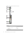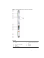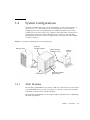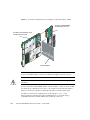
1
Sun Netra™ CP3220 Blade Server
User’s Guide
Sun Microsystems, Inc.
www.sun.com
Part No. 820-1982-12
January 2010, Revision 01
Submit comments about this document at: http://www.sun.com/hwdocs/feedback
Copyright © 2010 Sun Microsystems, Inc., 4150 Network Circle, Santa Clara, California 95054, U.S.A. All rights reserved.
This distribution may include materials developed by third parties.
Parts of the product may be derived from Berkeley BSD systems, licensed from the University of California. UNIX is a registered trademark in
the U.S. and in other countries, exclusively licensed through X/Open Company, Ltd.
Sun, Sun Microsystems, the Sun logo, Sun Netra, Netra, Solaris, SunVTS and the Netra logo are trademarks or registered trademarks of Sun
Microsystems, Inc., or its subsidiaries, in the U.S. and other countries.
AMD and Opteron are trademarks or registered trademarks of Advanced Micro Devices. PICMG is a registered trademark and AdvancedTCA
and ATCA are trademarks of the PCI Industrial Computer Manufacturers Group. The Adobe. logo is a registered trademark of Adobe Systems,
Incorporated. The Adobe. logo is a registered trademark of Adobe Systems, Incorporated.
Products covered by and information contained in this service manual are controlled by U.S. Export Control laws and may be subject to the
export or import laws in other countries. Nuclear, missile, chemical biological weapons or nuclear maritime end uses or end users, whether
direct or indirect, are strictly prohibited. Export or reexport to countries subject to U.S. embargo or to entities identified on U.S. export exclusion
lists, including, but not limited to, the denied persons and specially designated nationals lists is strictly prohibited
Use of any spare or replacement CPUs is limited to repair or one-for-one replacement of CPUs in products exported in compliance with U.S.
export laws. Use of CPUs as product upgrades unless authorized by the U.S. Government is strictly prohibited.
DOCUMENTATION IS PROVIDED "AS IS" AND ALL EXPRESS OR IMPLIED CONDITIONS, REPRESENTATIONS AND WARRANTIES,
INCLUDING ANY IMPLIED WARRANTY OF MERCHANTABILITY, FITNESS FOR A PARTICULAR PURPOSE OR NON-INFRINGEMENT,
ARE DISCLAIMED, EXCEPT TO THE EXTENT THAT SUCH DISCLAIMERS ARE HELD TO BE LEGALLY INVALID
Copyright © 2010 Sun Microsystems, Inc., 4150 Network Circle, Santa Clara, California 95054, Etats-Unis. Tous droits réservés.
Cette distribution peut comprendre des composants développés par des tierces parties.
Des parties de ce produit pourront être dérivées des systèmes Berkeley BSD licenciés par l’Université de Californie. UNIX est une marque
déposée aux Etats-Unis et dans d’autres pays et licenciée exclusivement par X/Open Company, Ltd.
Sun, Sun Microsystems, le logo Sun, Sun Netra, Netra, Solaris, SunVTS et le logo Netra sont des marques de fabrique ou des marques
déposées de Sun Microsystems, Inc., ou ses filiales, aux Etats-Unis et dans d’autres pays.
AMD et Opteron sont des marques de fabrique ou des marques déposées de Advanced Micro Devices. PICMG est une marque déposée et
AdvancedTCA et ATC A des marques de PCI Industrial Computer Manufacturers Group. Le logo Adobe. est une marque déposée de Adobe
Systems, Incorporated.
Ce produit est soumis à la législation américaine en matière de contrôle des exportations et peut être soumis à la règlementation en vigueur
dans d’autres pays dans le domaine des exportations et importations. Les utilisations , ou utilisateurs finaux, pour des armes nucléaires, des
missiles, des armes biologiques et chimiques ou du nucléaire maritime, directement ou indirectement, sont strictement interdites. Les
exportations ou reexportations vers les pays sous embargo américain, ou vers des entités figurant sur les listes d’exclusion d’exportation
américaines, y compris, mais de manière non exhaustive, la liste de personnes qui font objet d’un ordre de ne pas participer, d’une façon directe
ou indirecte, aux exportations des produits ou des services qui sont régis par la législation américaine en matière de contrôle des exportations et
la liste de ressortissants spécifiquement désignés, sont rigoureusement interdites.
L’utilisation de pièces détachées ou d’unités centrales de remplacement est limitée aux réparations ou à l’échange standard d’unités centrales
pour les produits exportés, conformément à la législation américaine en matière d’exportation. Sauf autorisation par les autorités des EtatsUnis, l’utilisation d’unités centrales pour procéder à des mises à jour de produits est rigoureusement interdite.
LA DOCUMENTATION EST FOURNIE "EN L’ETAT" ET TOUTES AUTRES CONDITIONS, DECLARATIONS ET GARANTIES EXPRESSES
OU TACITES SONT FORMELLEMENT EXCLUES, DANS LA MESURE AUTORISEE PAR LA LOI APPLICABLE, Y COMPRIS NOTAMMENT
TOUTE GARANTIE IMPLICITE RELATIVE A LA QUALITE MARCHANDE, A L’APTITUDE A UNE UTILISATION PARTICULIERE OU A
L’ABSENCE DE CONTREFACON.
Please
Recycle
Contents
Preface
1.
xv
Introduction
1–1
1.1
Overview
1.2
Features
1.3
Physical Description
1.4
1–2
1–2
1.3.1
Front Panel Components
1.3.2
Blade Server Diagram
1–3
1–6
System Configurations
1–7
1.4.1
AMC Modules
1–7
1.4.2
Advanced Rear Transition Module
1.5
Hot-Swap Support
1.6
System Components
1.7
1–3
1–8
1–12
1–12
1.6.1
Required Hardware Components
1–12
1.6.2
Optional Hardware Components
1–13
1.6.3
Software Components
Technical Support and Warranty
1.7.1
1–13
1–14
Locating the Blade Server Identification Information
1–14
iii
2.
Hardware Installation and Service
2.1
2.2
Safety and Tool Requirements
Equipment and Operator Safety
2.1.2
Materials and Tools Required
Installing the Blade Server
2.2.2
2.2.3
2–3
2–3
2.2.1.1
Check Power, Thermal, Environmental, and Space
Requirements 2–4
2.2.1.2
Local Network IP Addresses and Host Names
Worksheet 2–5
2.2.1.3
Installation Procedure Summary
Configuring the Hardware
2–6
2–6
2.2.2.1
Verify Chassis Fan Tray Upgrade
2–7
2.2.2.2
Installing Optional Components
2–7
2.2.2.3
Configuring the Advanced Rear Transition Module
Hardware 2–8
Installing the Sun Netra CP3220 Blade Server in an ATCA Shelf
2–8
▼
Installing an Advanced Rear Transition Module
To Install an ARTM
2.2.3.2
2.2.4
2–2
2–3
Preparing for the Installation
2.2.3.1
iv
2–2
2.1.1
2.2.1
2.3
2–1
2–8
10
Installing the Blade Server Into the Shelf
Connecting External I/O Cables
2–12
2–13
2.2.4.1
Connecting Cables to a System Console Running the
Solaris OS 2–13
2.2.4.2
Connecting Cables to the System Console Not Running
the Solaris OS 2–15
2.2.4.3
Netinstall Boot Device Map
Service Procedures
2–15
2–17
2.3.1
Hot-Swapping the Sun Netra CP3220 Blade Server
2.3.2
Powering Off the Sun Netra CP3220 Blade Server
2.3.3
Removing the Sun Netra CP3220 Blade Server
Sun Netra CP3220 Blade Server User’s Guide • January 2010
2–17
2–17
2–18
2.3.4
Powering On the System
2.3.5
Automatic Power-Off Events
2.3.6
Servicing DIMMs
2–18
2–19
2.3.6.1
DIMM Requirements
2–19
2.3.6.2
Installing a DDR2 DIMM
2.3.6.3
Removing a DDR2 DIMM
2–21
2–22
2.3.7
Installing the Optional Compact Flash Card
2.3.8
Installing Optional AMC Cards
2.3.9
Adding or Replacing a TOD Clock Battery
2.3.10
Changing Jumper Settings
2.3.11
2–24
2–26
2–29
2–29
2.3.10.1
Clearing the CMOS Setting Using Jumper 1
2.3.10.2
Changing the OOS LED Color
Changing OOS LED Behavior
▼
Viewing OOS LED Settings
34
▼
Setting OOS LED Behavior
35
2.3.12
3.
2–18
2–32
2–32
Resetting the Sun Netra CP3220 Blade Server
Software Configuration
2–29
2–36
3–1
3.1
Operating Systems
3–2
3.2
Software Updates
3–2
3.3
SunVTS Software
3–3
3.4
Configuring Sun Netra CP3220 For 1GbE or 10GbE Switches
3.5
Configuring Alternate OOS LED Behavior
3–4
3–5
▼
Displaying Configuration of OOS LED Behavior
▼
Setting Configuration of OOS LED Behavior
6
7
Contents
v
4.
Configuring and Using BIOS Firmware
4.1
About BIOS Settings
5.
vi
4–2
4.1.1
Navigating BIOS Screens
4.1.2
BIOS Considerations
4.1.3
4–1
4–2
4–2
4.1.2.1
BIOS Option ROMs on the Sun Netra CP3220 Blade
Server 4–2
4.1.2.2
AMD PowerNow! Feature Enabled by Default
Description of the BIOS Screens
4–3
4.2
Changing the Configuration of a BIOS Menu Item
4–4
4.3
Setting the Boot Device Using BIOS Setup Screens
4–5
4.4
Changing the BIOS Continuous Boot Setting
4.5
Setting Supervisor and User Passwords
4.6
Resetting the System Time and System Date
4.7
Updating the BIOS
4.8
Secondary BIOS Image
4.9
Use the Secondary BIOS Image
4.10
Perform a Live Firmware Upgrade
4.11
Power-On Self-Test
4.12
Changing POST Options
Hardware Architecture
4–9
4–12
4–12
4–12
4–13
4–14
4–14
5–1
5.1
Block Diagram
5.2
The AMD Opteron Processor
5.3
Memory
5.4
Networking and I/O
5–2
5–3
5–4
5–5
5.4.1
nVidia MCP55
5.4.2
PCI Express Bus
5.4.3
Dual BIOS
5.4.4
Trusted Platform Module (TPM)
5–5
5–6
5–6
Sun Netra CP3220 Blade Server User’s Guide • January 2010
4–9
5–6
4–11
4–3
5.5
5.4.5
Broadcom 5715C Gigabit Ethernet
5.4.6
Sun Dual 10-Gbit Ethernet/Quad 1-Gbit RGMII Network Interface
Chip (Sun 10 GbE Multithreaded Networking ASIC) 5–7
I/O Components
5–7
5.5.1
AMC Slots
5.5.2
EIDE/ATA for Compact Flash
5.5.3
SAS/SATA
A. Physical Characteristics
5–7
A–1
Form Factor
A.2
Power and Thermal Metrics
A–2
A–2
A.2.1
Processor Metrics
A.2.2
PICMG Board Cooling Requirements
A.2.3
PICMG ARTM Cooling Requirements
Connectors and Pinouts
A.3.1
A–2
A–3
A–3
A–4
Front Panel Connectors
A–4
A.3.1.1
Ethernet Port
A–4
A.3.1.2
USB Ports
A–5
A.3.1.3
Serial Port
A–6
A.3.2
AMC Connectors
A.3.3
Power Connector (Zone 1)
A.3.4
Data Transport Connector (Zone 2)
A.3.5
Advanced Rear Transition Module Connector (Zone 3)
B. BIOS Screens
Index
5–8
5–8
A.1
A.3
5–6
A–6
A–7
A–9
A–10
B–1
Index–1
Contents
vii
viii
Sun Netra CP3220 Blade Server User’s Guide • January 2010
Figures
FIGURE 1-1
Sun Netra CP3220 Dual-Core Blade Server (Front View)
1–4
FIGURE 1-2
Sun Netra CP3220 Quad-Core Blade Server (Front View)
1–5
FIGURE 1-3
Sun Netra CP3220 Blade Server (Component Side View)
1–6
FIGURE 1-4
Sun Netra CP3220 Blade Server in Shelf Enclosure
FIGURE 1-5
Sun Netra CP32x0 SAS Storage Advanced Rear Transition Module, Dual HD
FIGURE 1-6
Sun Netra CP3220 Blade Server, Backplane, and Relationship to ARTM
FIGURE 1-7
Sun Netra CP3220 Blade Server Barcode Labeling
FIGURE 2-1
Installing the Sun Netra CP32x0 ARTM
FIGURE 2-2
Injector/Ejector Latch and Locking Screw on the ARTM
FIGURE 2-3
Serial Port on the Sun Netra CP3220 Blade Server
FIGURE 2-4
Locating DIMM Slots 2–20
FIGURE 2-5
Installing a DIMM
FIGURE 2-6
Removing a DIMM
FIGURE 2-7
Compact Flash Location
FIGURE 2-8
Removing an AMC Filler Panel
FIGURE 2-9
Installing an AMC Card
FIGURE 2-10
Jumper 1 in the Run Position
FIGURE 2-11
Jumper 1 in the Reset Position
FIGURE 2-12
Jumper 2 in the Red Position
FIGURE 2-13
Sun Netra CP3220 Blade Server Front Panel
1–7
1–8
1–10
1–15
2–9
2–11
2–14
2–22
2–23
2–25
2–27
2–28
2–30
2–31
2–32
2–36
ix
FIGURE 4-1
BIOS Main Menu
FIGURE 4-2
Boot Settings Menu
FIGURE 4-3
Boot Device Priority Menu
FIGURE 4-4
Security Settings Menu
FIGURE 4-5
Change Password Menu
FIGURE 5-1
Block Diagram
FIGURE 5-2
AMD Opteron Processors Block Diagram
FIGURE A-1
Ethernet RJ-45 Connector
FIGURE A-2
Front Panel USB Connector
FIGURE A-3
Front Panel Serial RJ-45 Connector
FIGURE A-4
Power Distribution Connector (Zone 1) P10
FIGURE A-5
Zone 2 Connector
A–9
FIGURE A-6
Zone 3 Connector
A–11
FIGURE B-1
BIOS Menu Tree
B–2
FIGURE B-2
BIOS Main Menu
B–3
FIGURE B-3
Advanced Configuration Menu
FIGURE B-4
CPU Configuration Menu
FIGURE B-5
IDE Configuration Menu
FIGURE B-6
Super IO Configuration Menu
FIGURE B-7
ACPI Settings Menu
FIGURE B-8
Event Logging Details Menu
FIGURE B-9
MPS Configuration Menu
FIGURE B-10
PCI Express Configuration Menu
FIGURE B-11
SMBIOS Configuration Menu
FIGURE B-12
Remote Access Configuration Menu
FIGURE B-13
USB Configuration Menu
FIGURE B-14
Advanced PCI/PnP Settings Menu
FIGURE B-15
Advanced PCI/PnP Settings Menu Continued
FIGURE B-16
Boot Settings Menu
FIGURE B-17
Boot Settings Configuration Menu
x
4–6
4–7
4–8
4–10
4–10
5–2
5–4
A–4
A–5
A–6
A–7
B–3
B–4
B–4
B–5
B–5
B–6
B–6
B–7
B–7
B–8
B–8
B–9
B–10
B–10
Sun Netra CP3220 Blade Server User’s Guide • January 2010
B–9
FIGURE B-18
Boot Device Priority Menu
B–11
FIGURE B-19
Boot Hard Disk Drive Priority Menu
FIGURE B-20
Security Settings Menu
FIGURE B-21
Change Password Settings Menu
FIGURE B-22
Chipset Main Menu
FIGURE B-23
NorthBridge Chipset Configuration Menu
FIGURE B-24
NorthBridge Chipset Memory Configuration Menu
FIGURE B-25
NorthBridge Chipset ECC Configuration Menu
FIGURE B-26
NorthBridge Chipset DRAM Configuration Menu
FIGURE B-27
SouthBridge Chipset Configuration Menu
FIGURE B-28
Hyper Transport Configuration Menu
FIGURE B-29
Exit Options Menu
B–11
B–12
B–12
B–13
B–13
B–14
B–14
B–15
B–15
B–16
B–16
Figures
xi
xii
Sun Netra CP3220 Blade Server User’s Guide • January 2010
Tables
TABLE 1-1
I/O Configurations
1–11
TABLE 2-1
Local Area Network Information
TABLE 2-2
Netinstall Boot Device Table
TABLE 2-3
Extra MAC Addresses for Virtual LAN Configuration
TABLE 2-4
Pin Functions on Jumper 1
TABLE 4-1
BIOS Setup Screens Summary
TABLE 4-2
POST Options 4–15
TABLE A-1
Airflow Requirements
A–3
TABLE A-2
ARTM Pressure Drop
A–3
TABLE A-3
Ethernet Port Connector Pin Assignments
TABLE A-4
USB Port Pin Assignments
TABLE A-5
Serial Port Mini DIN 8-pin Connector Pinouts
TABLE A-6
Power Distribution Connector Pin Assignments
TABLE A-7
Zone 2 Connector Pin Assignments
TABLE A-8
J31 Connector Pin Assignments
A–11
TABLE A-9
J32 Connector Pin Assignments
A–12
TABLE A-10
J33 Connector Pin Assignments
A–12
2–5
2–15
2–16
2–30
4–3
A–4
A–5
A–6
A–7
A–10
xiii
xiv
Sun Netra CP3220 Blade Server User’s Guide • January 2010
Preface
The Sun Netra CP3220 Blade Server User’s Guide describes the hardware specifications,
function, and physical properties of the Sun Netra™ CP3220 blade server. It also
provides detailed information on the system firmware.
The Sun Netra CP3220 Blade Server User’s Guide is written for system integration
engineers, field applications and service engineers, and others involved in the
integration of this blade server into systems. This guide is written for personnel who
are familiar with the Solaris™ Operating System, the Linux operating systems and
Advanced Telecommunications Computing Architecture (ATCA) computing
environment.
How This Document Is Organized
Chapter 1 provides an overview of the Sun Netra CP3220 blade server.
Chapter 2 provides instructions on hardware installation.
Chapter 3 provides information on the supported operating systems and on the Sun
Validation Test Suite (SunVTS™) software.
Chapter 4 provides information on the Sun Netra CP3220 blade server firmware.
Chapter 5 provides information on hardware architecture.
Appendix A provides information on the Sun Netra CP3220 blade server physical
characteristics.
Appendix B provides first-level and second-level BIOS menu illustrations.
xv
Using UNIX Commands
This document might not contain information about basic UNIX® commands and
procedures such as shutting down the system, booting the system, and configuring
devices. Refer to the following for this information:
■
Software documentation that you received with your system
■
Solaris™ Operating System documentation, which is at:
http://docs.sun.com/app/docs/prod/solaris
Shell Prompts
xvi
Shell
Prompt
C shell
machine-name%
C shell superuser
machine-name#
Bourne shell and Korn shell
$
Bourne shell and Korn shell superuser
#
Sun Netra CP3220 Blade Server User’s Guide • January 2010
Typographic Conventions
Typeface*
Meaning
Examples
AaBbCc123
The names of commands, files,
and directories; on-screen
computer output
Edit your.login file.
Use ls -a to list all files.
% You have mail.
AaBbCc123
What you type, when contrasted
with on-screen computer output
% su
Password:
AaBbCc123
Book titles, new words or terms,
words to be emphasized.
Replace command-line variables
with real names or values.
Read Chapter 6 in the User’s Guide.
These are called class options.
You must be superuser to do this.
To delete a file, type rm filename.
* The settings on your browser might differ from these settings.
Related Documentation
The following table lists the documentation for this product. Except for the Important
Safety Information for Sun Hardware Systems, all the documents listed are available
online at:
http://docs.sun.com/app/docs/prod/cp3220.brd#hic
Application
Title
Part Number
Format
Location
Getting
Started
Sun Netra CP3220 Blade Server
Getting Started Guide
820-1981
Printed,
PDF,
HTML
Shipkit and Online
Latest
Information
Sun Netra CP3220 Blade Server
Product Notes
820-1980
PDF,
HTML
Online
Installation
and Usage
Sun Netra CP3220 Blade Server
User’s Guide (this manual)
820-1982
PDF,
HTML
Online
Safety and
Compliance
Sun Netra CP3220 Blade Server
Safety and Compliance Guide
820-1983
PDF,
HTML
Online
Safety
Important Safety Information for
Sun Hardware Systems
816-7190
Printed
Shipkit
Preface
xvii
Documentation, Support, and Training
Sun Function
URL
Documentation
http://docs.sun.com/documentation
Support
http://www.sun.com/support/
Training
http://www.sun.com/training/
Third-Party Web Sites
Sun is not responsible for the availability of third-party web sites mentioned in this
document. Sun does not endorse and is not responsible or liable for any content,
advertising, products, or other materials that are available on or through such sites
or resources. Sun will not be responsible or liable for any actual or alleged damage
or loss caused by or in connection with the use of or reliance on any such content,
goods, or services that are available on or through such sites or resources.
Sun Welcomes Your Comments
Sun is interested in improving its documentation and welcomes your comments and
suggestions. You can submit your comments by going to:
http://www.sun.com/hwdocs/feedback
Please include the title and part number of your document with your feedback:
Sun Netra CP3220 Blade Server User’s Guide, part number 820-1982-12.
xviii
Sun Netra CP3220 Blade Server User’s Guide • January 2010
CHAPTER
1
Introduction
This chapter provides an overview of the features, configurations, and system
requirements of the Sun Netra CP3220 blade server.
This chapter contains the following topics:
■
Section 1.1, “Overview” on page 1-2
■
Section 1.2, “Features” on page 1-2
■
Section 1.3, “Physical Description” on page 1-3
■
Section 1.4, “System Configurations” on page 1-7
■
Section 1.5, “Hot-Swap Support” on page 1-12
■
Section 1.6, “System Components” on page 1-12
■
Section 1.7, “Technical Support and Warranty” on page 1-14
1-1
1.1
Overview
The Sun Netra CP3220 blade server is a high-performance, single-board computer
based on an AMD Opteron X64 processor. The blade server is designed for high
availability in a switched network computing environment. This blade server is
compliant with Advanced Telecommunications Computing Architecture (ATCA)
specifications (PICMG 3.0 and PICMG 3.1). It can achieve greater performance levels
than previously supported CompactPCI® (cPCI) standards-based products targeted
for Telco markets.
The ATCA standard comprises the PICMG 3.0, 3.1, 3.2, and 3.3 versions of the
standard. The Sun Netra CP3220 blade server complies with the following
specifications:
1.2
■
PICMG 3.0, the base specification that defines the mechanical, power distribution,
system management, data transport, and regulatory guidelines
■
PICMG 3.1, which builds on the PICMG 3.0 base specification and on
IEEE 802.3-2003
Features
The Sun Netra CP3220 blade server features include:
1-2
■
ATCA card 322.25 mm x 280 mm, 1.2 inch slot card height
■
One 1207-pin socket, AMD Opteron dual or quad core versions at up to 68w
■
Double Data Rate (DDR-2) DIMMs, at up to 667 MHz DIMMs (8 modules per
card), up to 4-Gbyte/DIMM, in Very Low Profile design (0.72’ height)
■
nVidia MCP-55 PCIe and Southbridge media controller
■
Two AMC.1 Type 4S2E2 expansion slots (PCIe x4) supporting I/O expansion with
signaling to the Rear Transition Module (RTM)
■
Two 1000 BASE-T Ethernet base fabric (PICMG 3.0) interface ports (using
BCM5715C) from PCIe 4x
■
Two 10 Gigabit XUAI Ethernet Extended Fabric (PICMG 3.1) interface ports
(using Sun 10 GbE Multithreaded Networking ASIC) from PCIe x8
■
One Asychronous Serial port to RJ 45 on front panel, from SuperIO
■
One 10/100/1000BASE-T management port on front panel, with second
management LAN sent to the advanced rear transition module (ARTM)
Sun Netra CP3220 Blade Server User’s Guide • January 2010
■
E-IDE master to support one Compact Flash socket supporting up to 16-Gbyte
user flash (accessible when blade is removed from chassis)
■
Management support using on-board IPM controller (Renesas H8) that provides a
dual IPMB bus and IPMI redundant channels
■
Rear I/O expansion provided to an optional RTM, compatible with
AdvancedRTM shared architecture RTMs
■
SAS/SATA connectivity from RTM to each AMC slot (local MCP-55 SATA ports
are not used)
■
Supports AdvancedRTM Shared Architecture Zone 3 connector plans
■
Contains location for Trusted Platform Module chip (Infineon SLB 9635 TT 1.2),
which conforms to TCG v1.2 specifications
■
Designed to fit in a NEBS-compliant ATCA chassis
1.3
Physical Description
1.3.1
Front Panel Components
The following figures show the front panels of the Dual-Core and Quad-Core Sun
Netra CP3220 blade server.
Chapter 1
Introduction
1-3
FIGURE 1-1
Sun Netra CP3220 Dual-Core Blade Server (Front View)
RESET
Figure Legend
1-4
1
Locking screws
6
Reset button
2
Latches
7
10/100/1000 Ethernet management
port
3
Out-of-service (OOS) LED
8
Serial port
4
OK LED
9
USB ports
5
AMC card slots
Sun Netra CP3220 Blade Server User’s Guide • January 2010
FIGURE 1-2
Sun Netra CP3220 Quad-Core Blade Server (Front View)
Figure Legend
1
Locking screws
6
Reset button
2
Latches
7
10/100/1000 Ethernet management
port
3
Out-of-service (OOS) LED
8
Serial port
4
OK LED
9
USB ports
5
AMC card slots
Chapter 1
Introduction
1-5
1.3.2
Blade Server Diagram
FIGURE 1-3
Sun Netra CP3220 Blade Server (Component Side View)
Figure Legend
1-6
1
Compact Flash card
4
Zone 1 power connector
2
Zone 3 connectors
5
CPU Heatsink
3
Zone 2 connectors
6
DIMMs
Sun Netra CP3220 Blade Server User’s Guide • January 2010
1.4
System Configurations
Sun Netra CP3220 blade servers can be installed into an ATCA shelf (chassis), as
shown in FIGURE 1-4. The blade servers can be deployed in various electrical
configurations to suit user requirements. For example, the blade server can be
configured to boot from a network as a diskless client with either a front panel or
advanced rear transition module (ARTM) network connection. The Sun Netra
CP3220 blade server has a slot for a Compact Flash card (optional) and 8 DIMM
sockets for memory.
FIGURE 1-4
Sun Netra CP3220 Blade Server in Shelf Enclosure
Remote server
Rear I/O
transition module
Serial connector
10 meters or less
Terminal
console
Ethernet
connection
ATCA shelf
1.4.1
Sun Netra CP3220
blade servers
AMC Modules
The Sun Netra CP3220 blade server has two AMC slots, with four lanes each of PCIe,
to provide additional I/O to the front panels or to the rear of the enclosure when
used with an advanced rear transition module.
The Sun Netra CP3220 blade server supports AMC.1 Type 4E2 cards, as defined by
the AMC specification.
Chapter 1
Introduction
1-7
1.4.2
Advanced Rear Transition Module
You can install an optional Sun Netra CP32x0 Advanced Rear Transition Module
(ARTM) (FIGURE 1-5) into the rear of the ATCA shelf, opposite the Sun Netra CP3220
blade server (FIGURE 1-6).
The Sun Netra CP32x0 SAS Storage Advanced Rear Transition Module, Dual HD
provides the following components:
■
Up to two hot-pluggable SAS drives
■
One serial port
■
One 10/100/1000BASE-T Ethernet port with an RJ-45 connector
■
Two Infiniband style connectors for external SAS
FIGURE 1-5
1-8
Sun Netra CP32x0 SAS Storage Advanced Rear Transition Module, Dual HD
Sun Netra CP3220 Blade Server User’s Guide • January 2010
Figure Legend
1
Serial port
2
10/100/1000 MBASE-T management port
3
External SAS port (secondary)
4
External SAS port (primary)
5
Hard disk drives
6
RTM Alignment pin
7
Zone 3 connectors
8
OK LED
9
Out-of-service (OOS) LED
10
Blue Hot Swap LED
Note – Use only serial cables that are less than 10 meters in length.
FIGURE 1-6 shows the physical relationship between the Sun Netra CP3220 blade
server, the ARTM, and the backplane in a typical ATCA system.
Chapter 1
Introduction
1-9
FIGURE 1-6
Sun Netra CP3220 Blade Server, Backplane, and Relationship to ARTM
Sun Netra CP32x0 ARTM
(installed from the rear)
Sun Netra CP3220 blade server
(installed from the front)
ATCA backplane
Note – When using the Sun Netra CP32x0 ARTM with the Sun Netra CP3220 blade
server, use shielded cables of less than 10 meters in length for serial I/O ports.
Caution – You must use shielded cables for all ports to satisfy EMI compliance
standards.
You can order the CP32x0 ARTM, build a custom module, or buy one from an IHV.
You must set up a minimal set of I/O for a boot path for the host board and for a
path for console I/O to deliver commands and read board and system status.
Possible boot and console configurations are described in TABLE 1-1. Sun
Microsystems provides the Sun Netra CP3220 blade server and optionally, a
compatible Sun Netra CP32x0 ARTM. This module provides one
1-10
Sun Netra CP3220 Blade Server User’s Guide • January 2010
10/100/1000BASE-T per second Ethernet RJ-45 port from the host to the rear of the
system. This port can be used to accomplish, optionally, a network boot as a diskless
client. The other configurations require IHV hardware.
TABLE 1-1
I/O Configurations
I/O
Hardware Required
Description
Ethernet
Sun Netra CP32x0 ARTM,
supplied as an option for rear
access
The default boot path uses an Ethernet port; the blade server
runs in a diskless client configuration
SAS
Sun Netra 146-GB hard disk
and the Sun Netra CP32x0
ARTM
Available only with the optional Sun Netra CP32x0 SAS Storage
Advanced Rear Transition Module, Dual HD or through an
AMC card with SAS capabilities. When the optional rear
transition module is installed, connect to the drive(s) via SAS
ports on the rear transition module.
Serial data
Sun Netra CP3220 blade server Serial port A on the front panel provides the path of the default
console I/O.
Sun Netra CP32x0 ARTM rear When the optional transition module is installed, the module’s
serial port A will become the path of the default console I/O
transition module
(FIGURE 1-5).
Serial data
Compact
Flash
IDE Compact Flash card
Sun Netra CP3220 blade server supports one, optional IDE
Compact Flash drive, either 8-Gbyte (Type I) or 16-Gbyte (Type
II), installed in a Type II CF socket on the blade.
Chapter 1
Introduction
1-11
1.5
Hot-Swap Support
In general, the hot-swap process includes the orderly connection of the hardware
and software. The process uses hardware connection control to connect the hardware
in an orderly sequence. The process includes the use of pins of different lengths to
accomplish signal sequencing to protect the hardware and avoid corrupting the
system interface. For further details on hot-swap standards, see the ATCA hot-swap
specification.
The ATCA specification describes three hot-swap models: basic hot-swap, full
hot-swap, and HA hot-swap. When a Sun Netra CP3220 blade server functions as a
node board it supports all three hot-swap models.
1.6
System Components
This section contains the system-level hardware and software components, required
and optional, for the Sun Netra CP3220 blade server.
1.6.1
Required Hardware Components
The Sun Netra CP3220 blade server cannot be used as a stand-alone system. It is
designed to be used in an ATCA chassis for 8U boards. The minimum hardware
requirements needed to use the Sun Netra CP3220 blade server are as follows:
1-12
■
ATCA system enclosure for 8U boards (includes shelf, backplane, hub/switch
board, shelf manager, and power supply)
■
Console output device or serial terminal
■
Boot device (such as hard drive, network, or Compact Flash card)
■
Peripheral device for network access
■
IPMC (built in)
■
Cables for terminal and network connections
■
High-speed fans. If you are installing the Sun Netra CP3220 blade server in a Sun
Netra CT 900 server, the Sun Netra CT 900 server must have high-speed fan trays
to support the additional cooling needs of the Sun Netra CP3220 blade server. For
more information, see the Sun Netra CT 900 Server Upgrade Guide (820-3255).
Sun Netra CP3220 Blade Server User’s Guide • January 2010
Caution – You can damage the Sun Netra CP3220 blade server components if you
install the blade server in a chassis that does not provide sufficient cooling. For more
information, see Section 2.2.1.1, “Check Power, Thermal, Environmental, and Space
Requirements” on page 2-4.
Note – Use only shielded serial cables that are less than 10 meters in length.
1.6.2
Optional Hardware Components
You can order the following optional items:
■
Compact Flash card
■
AMC modules
■
Sun Netra CP32x0 ARTM
The Sun Netra CP32x0 ARTM enables rear system I/O access to the following:
■
■
Network
■
Boot device
■
With the ARTM-HD, two hot-swappable SAS hard disk drives
■
Console terminal (FIGURE 1-4).
Sun Netra CP3240 switch
The Sun Netra CP3240 switch is capable of operating at 10 GB, but is set by default
to operate at 1GB. To use the switch at 10 GB, perform a one-time configuration
procedure, available in the CP3x40 Switch Product Notes (820-3260).
1.6.3
Software Components
The Sun Netra CP3220 blade server has been tested for compatibility with the
Solaris™ 10 Operating System (Solaris OS) and WindRiver Linux.
Refer to the Sun Netra CP3220 Blade Server Product Notes (820-1980) for more Solaris
OS information, including a list of any required Sun Netra software patches and
support for subsequent versions of Solaris. You can view and download the latest
version of the product notes at the following web site:
http://docs.sun.com/app/docs/prod/cp3220.brd#hic
Refer to the appropriate vendor documentation for more information on your
operating system.
Chapter 1
Introduction
1-13
1.7
Technical Support and Warranty
Should you have any technical questions or support issues that are not addressed in
the Sun Netra CP3220 blade server documentation set or on the technical support
web site, contact your local Sun Services representative. This hardware carries a
one-year return-to-depot warranty.
For customers in the U.S. or Canada, please call 1-800-USA-4SUN (1-800-872-4786).
For customers in the rest of the world, you can find the World Wide Solution Center
nearest you at the following web site:
http://www.sun.com/contact/services_solutions.jsp
When you call Sun Services, be sure to indicate if the Sun Netra CP3220 blade server
was purchased separately and is not associated with a system. Please have the blade
server identification information ready. For proper identification of the blade server,
be prepared to give the representative the blade server part number, serial number,
and date code (FIGURE 1-7).
1.7.1
Locating the Blade Server Identification
Information
The Sun Netra CP3220 blade server part number, serial number, revision number,
and media access control (MAC) address are printed on stickers located on the Sun
Netra CP3220 blade server (FIGURE 1-7).
The Sun barcode label provides the following information:
■
Blade server serial number (for example, 1005LCB-07296R0912), which is on the
barcode label
The part number/dash/revision/date code label provides the following
information:
■
Blade server part number (for example, 3753529), which is the first seven digits on
the part number label
■
Product dash number (for example, -01)
■
Revision number (for example, REV: 01)
The MAC address label contains the base MAC address for the blade server in
printed and barcode form. Is it an orange label located below the AMC slots.
1-14
Sun Netra CP3220 Blade Server User’s Guide • January 2010
FIGURE 1-7
Sun Netra CP3220 Blade Server Barcode Labeling
Part number label
Serial number
label
Chapter 1
Introduction
1-15
1-16
Sun Netra CP3220 Blade Server User’s Guide • January 2010
CHAPTER
2
Hardware Installation and Service
This chapter describes the Sun Netra CP3220 blade server hardware installation and
service procedures.
This chapter contains the following topics:
■
Section 2.1, “Safety and Tool Requirements” on page 2-2
■
Section 2.2, “Installing the Blade Server” on page 2-3
■
Section 2.3, “Service Procedures” on page 2-17
2-1
2.1
Safety and Tool Requirements
2.1.1
Equipment and Operator Safety
Refer to the Important Safety Information for Sun Hardware Systems (816-7190) for
general safety information.
Read the following safety statements that are specific to the Sun Netra CP3220 blade
server carefully before you install or remove any part of the system.
Caution – Depending on the particular chassis design, operations with open
equipment enclosures can expose the installer to hazardous voltages with a
consequent danger of electric shock. Ensure that line power to the equipment is
disconnected during operations that make high voltage conductors accessible.
The installer must be familiar with commonly accepted procedures for integrating
electronic systems and the general practice of Sun systems integration and
administration. Although parts of these systems are designed for hot-swap
operation, other components must not be subjected to such stresses. Work with
power connected to a shelf only when necessary, and follow these installation
procedures to avoid equipment damage.
This equipment is sensitive to damage from electrostatic discharge (ESD) from
clothing and other materials. Use the following antistatic measures during an
installation:
■
If possible, disconnect line power from the shelf when servicing a system or
installing a hardware upgrade. If the shelf cannot be placed on a grounded
antistatic mat, connect a grounding strap between the facility electrical input
ground (usually connected to the shelf) and facility electrical service ground.
■
Use an antistatic wrist strap when performing the following tasks:
■
Removing a blade server from its antistatic bag
■
Connecting or disconnecting blade servers, boards, or peripherals
The other end of the antistatic wrist strap lead should be connected to one of the
following:
2-2
■
A ground mat
■
The chassis metal as a ground
Sun Netra CP3220 Blade Server User’s Guide • January 2010
The grounded mat or the chassis must be connected to a facility ground to
prevent a floating ground.
2.1.2
■
Keep blade servers in the antistatic bags until they are needed.
■
Remove a blade server from its antistatic bag only when wearing a properly
connected ground strap.
■
Place blade servers that are out of their antistatic bags on an antistatic mat if one
is available and the mat is grounded to a facility electrical service ground. Do not
place blade servers on top of an antistatic bag unless the outside of the bag also
has antistatic protective properties.
Materials and Tools Required
The tools required for installation and service are:
■
Phillips screwdrivers: No. 1 (required), No. 2 (optional)
■
Antistatic wrist strap
■
Terminal console
■
Serial cable of less than 10 meters in length to connect the Sun Netra CP3220
blade server with a system console
Refer to Section 1.6, “System Components” on page 1-12 for information on
hardware requirements.
2.2
Installing the Blade Server
2.2.1
Preparing for the Installation
Prepare for installation by reading and performing the following steps.
1. Become familiar with the contents of the documentation referenced in the steps.
2. Verify that all listed hardware and software are available (see Section 1.6, “System
Components” on page 1-12).
3. Check power, thermal, environmental, and space requirements (see
Section 2.2.1.1, “Check Power, Thermal, Environmental, and Space Requirements”
on page 2-4).
Chapter 2
Hardware Installation and Service
2-3
4. Verify that local area network (LAN) preparations are completed (see
Section 2.2.1.2, “Local Network IP Addresses and Host Names Worksheet” on
page 2-5).
5. Ensure that the host names and their network IP addresses are allocated and
registered at the site. Record this information in TABLE 2-1.
2.2.1.1
Check Power, Thermal, Environmental, and Space
Requirements
Observe that your environment meets the following requirements:
■
Your enclosure specifications can support the sum of the specified maximum
blade server power loads. (See Section A.2, “Power and Thermal Metrics” on
page A-2).
■
Facility power loading specifications can support the rack or enclosure
requirements.
■
Your enclosure specifications can support the cooling airflow requirements.
The Sun Netra CP3220 blade server fits into a standard ATCA shelf. If your
installation requirements are different, contact your field applications engineer.
2-4
Sun Netra CP3220 Blade Server User’s Guide • January 2010
2.2.1.2
Local Network IP Addresses and Host Names Worksheet
Collect the information listed in TABLE 2-1 to connect hosts to the LAN. Ask your
network administrator for help, if necessary. This information is not needed for a
stand-alone installation.
TABLE 2-1
Local Area Network Information
Information Needed
Your Information
IP address* and host name for each Sun
Netra CP3220 client
Domain name
Type of name service and corresponding
name server names and IP addresses—for
example DNS and NIS (or NIS+)
Subnet mask
Gateway router IP address
Network File System (NFS) server names
and IP addresses
Web server URL
* Local IP addresses are not needed if they are assigned by a network Dynamic Host Configuration Protocol
(DHCP) server.
You may need the MAC (Ethernet) addresses of the local hosts to make name server
database entries. You can see the MAC address in the console output while booting
the blade server. You can also find it on the barcode label on the blade server (see
Section 1.7.1, “Locating the Blade Server Identification Information” on page 1-14).
Chapter 2
Hardware Installation and Service
2-5
2.2.1.3
Installation Procedure Summary
This section summarizes the high-level procedures that are required to install the
Sun Netra CP3220 blade server. Ensure that you are familiar with the information in
Section 2.2.2, “Configuring the Hardware” on page 2-6 through the end of Chapter 2
before installing the blade server.
The process to set up and configure a Sun Netra CP3220 blade server in a system
includes the following procedures:
1. Configure the blade server’s physical hardware.
For example, install memory and AMC cards, and set switches, as necessary
(Section 2.2.2, “Configuring the Hardware” on page 2-6).
2. Physically install the ARTM as necessary (Section 2.2.3.1, “Installing an Advanced
Rear Transition Module” on page 2-8).
3. Physically install the Sun Netra CP3220 blade server, and any peripheral boards
into the ATCA shelf Section 2.2.3, “Installing the Sun Netra CP3220 Blade Server
in an ATCA Shelf” on page 2-8).
4. Connect the nodes to a local network. (Section 2.2.4, “Connecting External I/O
Cables” on page 2-13).
5. If you are running the Solaris Operating System on the Sun Netra CP3220 blade
server, and want to verify system integrity, download and install SunVTS
(Section 3.1, “Operating Systems” on page 3-2).
2.2.2
Configuring the Hardware
This section lists hardware installation and settings that might apply to your blade
server configuration. Read and perform the procedures, as necessary, before
installing the Sun Netra CP3220 blade server into the ATCA shelf.
2-6
Sun Netra CP3220 Blade Server User’s Guide • January 2010
2.2.2.1
Verify Chassis Fan Tray Upgrade
Caution – The Sun Netra CT 900 server fan tray upgrade kit (594-4953) must be
installed in the chassis before the Sun Netra CP3220 blade server is installed. This
fan tray upgrade is required to provide adequate cooling and prevent the system
from overheating or shutting down due to an over temperature condition that can
occur with the older fan trays.
●
To verify if the fan tray upgrade is installed on a Sun Netra CT 900 server, log
into the Shelf Manager and issue the following command for fan trays 1,2, and
3:
# clia fruinfo fan_tray 1 | grep "Product Part"
If "Product Part / Model Number = 371-3033-xx", an upgraded fan tray is
installed. If "Product Part / Model Number" is not 371-3033, an old fan tray is
installed and the upgrade is required. Refer to the Sun Netra CT 900 Server
Upgrade Guide (820-3255) for more information.
2.2.2.2
Installing Optional Components
Use the following table to locate your options and installation instructions.
DIMMs
Section 2.3.6.1, “DIMM Requirements” on page 2-19
Section 2.3.6.2, “Installing a DDR2 DIMM” on page 2-21
Compact Flash card
Section 2.3.7, “Installing the Optional Compact Flash Card” on
page 2-24
AMC card
Section 2.3.8, “Installing Optional AMC Cards” on page 2-26
Chapter 2
Hardware Installation and Service
2-7
2.2.2.3
Configuring the Advanced Rear Transition Module Hardware
If you are using a Sun Netra CP32x0 Advanced Rear Transition Module (ARTM),
refer to the appropriate documentation. See Section , “Related Documentation” on
page -xvii.
You can also see Section A.3, “Connectors and Pinouts” on page A-4 for detailed
connector pin assignments for the Sun Netra CP3220 blade server.
2.2.3
Installing the Sun Netra CP3220 Blade Server in
an ATCA Shelf
If you are installing the Sun Netra CP3220 blade server with the Sun Netra CP32x0
ARTM, install the Sun Netra CP32x0 ARTM at the rear of the server and then install
the Sun Netra CP3220 blade server in the front of the server. Even though you will
be installing the Sun Netra CP32x0 ARTM first, look at the front of the server and
locate the slot number where you will be installing the Sun Netra CP3220 blade
server. Then go to the back of the server and install the Sun Netra CP32x0 ARTM in
that particular slot. If you do not install the Sun Netra CP3220 blade server and the
Sun Netra CP32x0 ARTM in corresponding slots, the system will recognize the Sun
Netra CP3220 blade server but not the Sun Netra CP32x0 ARTM.
Note – Slots 1 through 6 and 9 through 14 are available for Sun Netra CP3220 blade
servers. Slots 7 and 8 are reserved for the switch card.
2.2.3.1
Installing an Advanced Rear Transition Module
A compatible advanced rear transition module (ARTM) can be used with the Sun
Netra CP3220 blade server for rear I/O access. The ARTM enables access to the
network, a boot device, and a console terminal. You can use the Sun Netra CP32x0
ARTM or you can design your own compatible ARTM. For more information, see
Section 1.4.2, “Advanced Rear Transition Module” on page 1-8
2-8
Sun Netra CP3220 Blade Server User’s Guide • January 2010
FIGURE 2-1
Installing the Sun Netra CP32x0 ARTM
Chapter 2
Hardware Installation and Service
2-9
▼ To Install an ARTM
1. Verify that you have taken the necessary antistatic precautions.
See Section 2.1.1, “Equipment and Operator Safety” on page 2-2.
2. From the rear of the system, choose an appropriate slot for the ARTM.
The ARTM must be installed, inline, behind a compatible Sun Netra blade server
(Sun Netra CP3220 blade server or Sun Netra CP3260 blade server).
For example, if the Sun Netra CP3220 blade server will be installed in slot 3, the
corresponding ARTM must be installed at the back of the system in slot 3
(FIGURE 2-1). If you do not install the ARTM and the Sun Netra CP3220 blade
server in corresponding slots, the system will recognize the Sun Netra CP3220
blade server, but not the ARTM.
Note – Slots 1 through 6 and 9 through 14 are available for Sun Netra CP3220 blade
servers. Slots 7 and 8 are reserved for the switch card.
3. Remove the slot filler panel from the selected slot, if necessary.
4. Retrieve the ARTM from the ship kit.
5. Prepare the ARTM by opening the injector/ejector latch at the top of the
module (FIGURE 2-2).
2-10
Sun Netra CP3220 Blade Server User’s Guide • January 2010
FIGURE 2-2
Injector/Ejector Latch and Locking Screw on the ARTM
6. Carefully align the edges of the ARTM with the card guides in the appropriate
slot.
Look into the enclosure to verify correct alignment of the rails in the guides.
7. Keep the ARTM aligned in the guides, and slide the ARTM in until the
injector/ejector latches engage the card cage.
8. Push the ARTM into the backplane connectors, and close the latch.
9. Tighten the locking screws to ensure that the module is secured into the ATCA
shelf.
Chapter 2
Hardware Installation and Service
2-11
10. Install the Sun Netra CP3220 blade server into the front of the ATCA shelf in
the corresponding slot.
See Section 2.2.3.2, “Installing the Blade Server Into the Shelf” on page 2-12 for
instructions.
2.2.3.2
Installing the Blade Server Into the Shelf
Note – You can install the Sun Netra CP3220 blade server in any available slot in the
ATCA shelf except for slots 7 and 8.
1. If you have installed an ARTM, go to the front of the system and locate the
same slot number where you installed the ARTM.
2. Remove the filler panel from the blade server slot, if necessary.
The filler panel is secured to the card cage using two screws, one at the top of the
filler panel, the other at the bottom. Store the filler panel in a safe place; you
might need to use it again if you remove a blade server for an extended time.
3. Prepare the Sun Netra CP3220 blade server by opening the injector/ejector
latches (FIGURE 2-2).
4. Carefully align the edges of the blade server with the guides in the appropriate
slot.
Look into the enclosure to verify correct alignment of the rails in the guides.
5. Keep the blade server aligned in the guides and slide the blade server in until
the injector/ejector latches engage the card cage.
6. Push the blade server slightly into the backplane connectors and close the
latches to seat the blade server in the connectors.
When the lower latch is closed, the blue Hot-Swap LED blinks while the blade
server is initializing. The blue LED turns off and the green OK LED lights when
the blade server is ready for use.
7. Tighten the locking screws and the top and the bottom of the Sun Netra CP3220
blade server to ensure that it is secured to the ATCA shelf (FIGURE 2-2).
The blade server is now completely installed and will power on automatically.
2-12
Sun Netra CP3220 Blade Server User’s Guide • January 2010
2.2.4
Connecting External I/O Cables
Front panel ports are typically used for maintenance and troubleshooting purposes
in installed and running systems. External I/O cables are connected to the Sun Netra
CP3220 blade server or to the Sun Netra CP32x0 ARTM.
To connect each of these following cables:
■
For Ethernet connections, Category 5e or better network cable is required.
Connect one end of the Ethernet cable to a suitable 10/100/1000 MBASE-T
Ethernet switch and the other end to one of the Ethernet ports on the Sun Netra
CP3220 blade server or Sun Netra CP32x0 ARTM. By default, when a Sun Netra
CP32x0 ARTM is installed, the Ethernet cable is connected only to the Ethernet
port on the ARTM. Refer to the Sun Netra CP32x0 ARTM SAS Storage Advanced
Rear Transition Module, Dual HD User’s Guide (820-0460) for more information.
Note – Although the front panel Ethernet port does not support gigabit Ethernet, it
can be connected to a gigabit switch capable of 10/100/1000 MBASE-T Ethernet.
■
Attach asynchronous serial I/O cables from serial communication devices to the
RJ-45 serial ports on the CP3220 blade server or Sun Netra CP32x0 ARTM.
Note – The front and rear serial ports use the same physical wire, so only one serial
port, either the front or the rear, can be used at a time.
2.2.4.1
Connecting Cables to a System Console Running the Solaris
OS
1. Connect a shielded serial cable to the serial console port on the front panel of
the Sun Netra CP3220 blade server (FIGURE 2-3) or the Sun Netra CP32x0 ARTM.
2. Connect the other end of the serial cable to the serial port of the system serving
as the serial console.
Chapter 2
Hardware Installation and Service
2-13
FIGURE 2-3
Serial Port on the Sun Netra CP3220 Blade Server
RESET
Serial port
3. Use one of the following to establish a full-duplex serial terminal connection
with the Sun Netra CP3220 blade server:
2-14
■
The tip utility
■
The minicom utility
Sun Netra CP3220 Blade Server User’s Guide • January 2010
■
A telnet utility (Connect to the proper port on a Network Terminal Server to
which the Sun Netra CP3220 is connected.)
■
Another suitable serial communications program on the system console
For example, if you are using a UNIX system as the system console, at the UNIX
prompt in a command tool or shell tool, or serial port A, type:
# tip -9600 /dev/ttya
2.2.4.2
Connecting Cables to the System Console Not Running the
Solaris OS
1. Connect a shielded serial cable to the serial console port on the front panel of
the Sun Netra CP3220 blade server (FIGURE 2-3) or the Sun Netra CP32x0 ARTM.
2. Connect the other end of the serial cable to the serial port of the system serving
as the system console.
3. Set the serial communications settings to 9600 baud, 8 bit, 1 stop bit, no parity,
and no handshake.
2.2.4.3
Netinstall Boot Device Map
TABLE 2-2 provides a map of netinstall boot devices. You may need this information
to understand which MAC address is associated with the system IP address on the install
server.
For example, the Base Fabric interface is connected to the switch model-number in
slot 8 of the ATCA shelf. To install to this device, select the xxx Ethernet interface
from the BIOS setup menus.
TABLE 2-2
Netinstall Boot Device Table
MAC Address
Solaris
Device
Hardware
Device
Switch Slot
Connection
0:3:ba.xx.xx.xn+0
bge0
(BMC5715C)
Base Fabric 0
Slot 7
0:3:ba.xx.xx.xn+1
bge1
(BMC5715C)
Base Fabric 1
Slot 8
0:3:ba.xx.xx.xn+2
nge0
(MCP55)
mgtA (front panel)
0:3:ba.xx.xx.xn+3
nge1
(MCP55)
mgtB (rear panel)
0:3:ba.xx.xx.xn+4
nxge0
(Sun 10 GbE
Multithreaded
Networking ASIC 10
GB)
Extended Fabric 0
Connects to...
Chapter 2
Slot 7
Hardware Installation and Service
2-15
Netinstall Boot Device Table (Continued)
TABLE 2-2
MAC Address
Solaris
Device
Hardware
Device
0:3:ba.xx.xx.xn+5
nxge1
(Sun 10 GbE
Multithreaded
Networking ASIC 10
GB)
Extended Fabric 1
0:3:ba.xx.xx.xn+6
nxge2
(Sun 10 GbE
Multithreaded
Networking ASIC 1
GB)
AMC and RTM
0:3:ba.xx.xx.xn+7
nxge3
(Sun 10 GbE
Multithreaded
Networking ASIC 1
GB)
AMC and RTM
Connects to...
Switch Slot
Connection
Slot 8
The Sun Netra CP3220 blade server supports virtual LAN configuration for the Sun
10 GbE Multithreaded Networking ASIC ports (MAC addresses 4, 5, 6, and 7). When
configured, the virtual LAN feature enables the assignment of multiple MAC
address to one port. TABLE 2-3 lists the extra MAC addresses available for the Sun 10
GbE Multithreaded Networking ASIC ports.
TABLE 2-3
2-16
Extra MAC Addresses for Virtual LAN Configuration
Primary MAC Address
Additional MAC Addresses
0:3:ba.xx.xx.xn+4
0:3:ba.xx.xx.xn+8 through
0:3:ba.xx.xx.xn+14
0:3:ba.xx.xx.xn+5
0:3:ba.xx.xx.xn+15 through
0:3:ba.xx.xx.xn+21
0:3:ba.xx.xx.xn+6
0:3:ba.xx.xx.xn+22 through
0:3:ba.xx.xx.xn+28
0:3:ba.xx.xx.xn+7
0:3:ba.xx.xx.xn+29 through
0:3:ba.xx.xx.xn+35
Sun Netra CP3220 Blade Server User’s Guide • January 2010
2.3
Service Procedures
2.3.1
Hot-Swapping the Sun Netra CP3220 Blade Server
You can remove the Sun Netra CP3220 blade server without powering off the entire
chassis by performing these steps.
1. Power off the blade server.
See Section 2.3.2, “Powering Off the Sun Netra CP3220 Blade Server” on
page 2-17.
2. Remove the blade server.
See Section 2.3.3, “Removing the Sun Netra CP3220 Blade Server” on page 2-18.
2.3.2
Powering Off the Sun Netra CP3220 Blade Server
1. Shut down the operating system.
Log in and shut down any OS operating on the blade server or its companion
ARTM.
2. Deactivate the blade server.
Log in to the shelf manager and deactivate the blade server in the target slot.
For example, to shut down the blade server in slot 3, log in to the shelf manager
and type:
# clia deactivate board 3
Wait for the blue Hot-Swap LED to light steadily before removing the blade
server.
Chapter 2
Hardware Installation and Service
2-17
2.3.3
Removing the Sun Netra CP3220 Blade Server
1. Power off the Sun Netra CP3220 blade server.
Use the instructions in Section 2.3.2, “Powering Off the Sun Netra CP3220 Blade
Server” on page 2-17.
2. If installed, remove all cables from the front of the Sun Netra CP3220 blade
server.
3. Loosen the locking screws to release the blade server from the ATCA shelf.
4. When the blue Hot-Swap LED lights steadily, release the upper latch and the
lower latch at the same time to unseat the blade server from the connectors.
5. Remove the blade server from the ATCA shelf and place the blade server on an
antistatic mat.
2.3.4
Powering On the System
Sun Netra CP3220 blade servers are powered on automatically via the H8 BMC
when you install the blade server into a slot in the ATCA shelf. Once installed, the
blade server sequences through power-on states until it is fully powered on.
2.3.5
Automatic Power-Off Events
A power-off sequence is initiated either by a request from the shelf manager or a
fault condition. The Sun Netra CP3220 blade server shuts down to standby power
mode when the following upper critical threshold conditions are met:
■
Detection of DC input (both -48V A and -48V B) drop for more than 5ms
■
Processor thermal trip drops to standby mode
Thermal trip of DC brick turns off all local power (standby included)
2-18
Sun Netra CP3220 Blade Server User’s Guide • January 2010
2.3.6
Servicing DIMMs
2.3.6.1
DIMM Requirements
The Sun Netra CP3220 blade server supports a total of eight DIMMs and the
maximum memory capacity of 32 Gbytes (using four 4-Gbyte DIMMs). The Sun
Netra CP3220 blade server accommodates the following DIMMs and configurations:
■
Up to eight standard DDR2-667 (PC2-5300) SDRAM registered/ECC DIMMs
■
DIMMs must be installed in matching pairs, in the lowest-number slots available
■
DIMM pair 0 must always be installed first
■
2-Gbyte and 4-Gbyte, DDR2 modules are supported
■
Maximum of 32 Gbytes in eight slots
The Sun Netra CP3220 blade server supports DIMMs that have the following
characteristics:
■
A 144-bit wide data bus DDR2 interface (2x64-bit data + 2x8-bit ECC)
■
DDR2 DIMM: 4.4 - 7.0 watts (1.8 V)
■
Very low profile (VLP) with a maximum height of 0.72 inch (18.3 mm)
■
Data Bus: 64 bits, Clock Rate: 333 MHz, Data Rate: 667, MegaTransfers,
Throughput 5.3 Gbytes/second
Chapter 2
Hardware Installation and Service
2-19
FIGURE 2-4
Locating DIMM Slots
B A
B A
Pair 0
B A
B A
Pair 2
Pair 1
Pair 3
Populate DIMMs in matching pairs, starting with Pair 0, then adding Pair 1, Pair 2,
and Pair 3 as needed.
2-20
Sun Netra CP3220 Blade Server User’s Guide • January 2010
2.3.6.2
Installing a DDR2 DIMM
The following procedure provides a general guide for installing additional memory.
However, for specific directions on installing DIMMs on the Sun Netra CP3220 blade
server, refer to the documentation that shipped with the DIMMs.
1. Access the blade server by performing one of the following procedures:
■
If the Sun Netra CP3220 blade server is installed in an ATCA shelf, remove the
blade server from the shelf as explained in Section 2.3.3, “Removing the Sun
Netra CP3220 Blade Server” on page 2-18.
■
Remove the Sun Netra CP3220 blade server from its antistatic envelope and place
it on an ESD mat near the ATCA shelf.
2. Take antistatic precautions: Attach and electrically ground the wrist strap.
Caution – Always wear a grounded antistatic wrist strap when handling DIMMs.
3. Locate the DIMM connectors on the Sun Netra CP3220 blade server.
Select the connectors where you will install the DIMM. See FIGURE 2-4 for DIMM
slot locations.
Caution – Do not remove the DIMM from its antistatic container until you are
ready to install the DIMM on the Sun Netra CP3220 blade server. Handle the DIMM
only by its edges. Do not touch DIMM components or metal parts. Always wear a
grounded antistatic wrist strap when handling DIMM.
4. Remove the DIMM from its protective packaging, holding the module only by
the edges.
5. Holding the DIMM upright to the blade server, insert the bottom edge of the
DIMM into the bottom of the slot’s hinge-style connector (FIGURE 2-5).
Caution – Evenly engage the DIMM in its hinge-style slot; uneven contact can
cause shorts that will damage the Sun Netra CP3220 blade server. Do not rock the
DIMM into place. Ensure that all contacts engage at the same time. You will feel or
hear a click when the DIMM properly seats in the connector.
The socket and module are both keyed, which means that the DIMM can be
installed only one way. With even pressure, push simultaneously on both upper
corners of the DIMM until its bottom edge (the edge with the gold fingers) is
firmly seated in the connector.
Chapter 2
Hardware Installation and Service
2-21
FIGURE 2-5
Installing a DIMM
6. Press the top edge of the DIMM toward the blade server until the retainer clips
click into place in the notches on the DIMM sides (FIGURE 2-5).
The small metal retainer clips on each side of the DIMM slot are spring-loaded,
and they should click into place in the notches on the sides of the DIMM.
2.3.6.3
Removing a DDR2 DIMM
If you are returning the DIMM or the blade server for service, or if you are replacing
a DIMM with another DIMM, remove the DIMM from the Sun Netra CP3220 blade
server.
Note – Safely store the original factory-shipped DIMM and related DIMM
packaging. Store any removed DIMM in the new DIMM packaging.
To remove a DIMM from the Sun Netra CP3220 blade server, perform the following
steps:
1. Access the blade server by performing one of the following procedures:
2-22
■
If the Sun Netra CP3220 blade server is installed in an ATCA shelf, remove the
blade server from the shelf as explained in Section 2.3.3, “Removing the Sun
Netra CP3220 Blade Server” on page 2-18.
■
Remove the Sun Netra CP3220 blade server from its antistatic envelope and place
it on an ESD mat near the ATCA shelf.
Sun Netra CP3220 Blade Server User’s Guide • January 2010
If an ESD mat is not available, you can place the blade server on the antistatic
envelope in which it was packaged.
Caution – Do not place blade servers on top of an antistatic bag unless the outside
of the bag also has antistatic protective properties.
2. Take antistatic precautions: Attach and electrically ground the wrist strap.
Caution – Always wear a grounded antistatic wrist strap when handling DIMMs.
3. Simultaneously pull both spring retainer clips outward from the slot for the
DIMM you want to remove.
4. Grasp the DIMM by the edges, and carefully pull it out of its connector.
Place it in an antistatic bag.
FIGURE 2-6
Removing a DIMM
5. If you are replacing the DIMM you removed with a new DIMM, install it as
described in Section 2.3.6.2, “Installing a DDR2 DIMM” on page 2-21.
Note – Before installing a replacement DIMM, verify that the new DIMM is the
same size as its paired DIMM.
Chapter 2
Hardware Installation and Service
2-23
2.3.7
Installing the Optional Compact Flash Card
An IDE Compact Flash card can be installed on the Sun Netra CP3220 blade server.
The Compact Flash card is not hot-swappable, and there is no access to the Compact
Flash card once the Sun Netra CP3220 is installed in an ATCA shelf.
1. Access the blade server by performing one of the following procedures:
■
If the Sun Netra CP3220 blade server is installed in an ATCA shelf, remove the
blade server from the shelf as explained in Section 2.3.3, “Removing the Sun
Netra CP3220 Blade Server” on page 2-18.
■
Remove the Sun Netra CP3220 blade server from its antistatic envelope and place
it on an ESD mat near the ATCA shelf.
If an ESD mat is not available, you can place the blade server on the antistatic
envelope in which it was packaged.
Caution – Do not place blade servers on top of an antistatic bag unless the outside
of the bag also has antistatic protective properties.
2. Locate the Compact Flash connector.
The connector is located on the blade server, under the sheet metal protecting
AMC slot B1(FIGURE 2-7).
3. To install the Compact Flash card, use the arrow on the card as a guide to insert
the card into the Compact Flash connector.
2-24
Sun Netra CP3220 Blade Server User’s Guide • January 2010
FIGURE 2-7
Compact Flash Location
Note – Sun Compact Flash cards have a life time of 2,000,000 write/erase cycles.
Users are responsible for ensuring that the operating system and applications do not
exceed this limitation.
Chapter 2
Hardware Installation and Service
2-25
2.3.8
Installing Optional AMC Cards
An Advanced Mezzanine card (AMC) is a card or module that provides additional
functionality to the Sun Netra CP3220 blade server. The blade server contains two
AMC slots in which you can install an optional AMC device. An AMC device can be
installed and removed via a cutout in the front panel while the Sun Netra CP3220
blade server is installed in the chassis.
Note – The following procedure provides a general set of instructions for installing
AMC modules on the Sun Netra CP3220 blade server. Refer to the AMC module
manufacturer’s documentation for specific instructions on installing these devices.
1. Retrieve the wrist strap from the modules’s shipping kit.
2. Attach the adhesive copper strip of the antistatic wrist strap to the metal
chassis.
Wrap the other end twice around your wrist, with the adhesive side against your
skin.
3. Remove the AMC slot filler panel from the blade server’s front panel FIGURE 2-8.
2-26
Sun Netra CP3220 Blade Server User’s Guide • January 2010
FIGURE 2-8
Removing an AMC Filler Panel
4. Retrieve the AMC module from its shipping kit and place it on an antistatic
surface.
5. Insert the AMC module through the cutout and into the AMC slot FIGURE 2-9.
Chapter 2
Hardware Installation and Service
2-27
FIGURE 2-9
Installing an AMC Card
Caution – Do not use excessive force when installing the AMC module into the slot.
You might damage the AMC connector on the Sun Netra CP3220 blade server,
causing permanent damage to the AMC module or the blade server. If the AMC
module does not seat properly when you apply even pressure, remove the AMC
module and carefully reinstall it.
6. Carefully insert the AMC card into the AMC slot, ensuring that the edge of the
card is installed into the card guides on both edges.
2-28
Sun Netra CP3220 Blade Server User’s Guide • January 2010
7. Press on the front face of the AMC card until the card is fully seated into the
AMC connector.
8. Press the black ejector in, toward the AMC card, to activate the card.
9. Refer to the AMC module documentation for software and cabling installation
instructions.
2.3.9
Adding or Replacing a TOD Clock Battery
The optional TOD battery must be type CR1632, with a minimum of 4ma abnormal
charging current rating (for example; a Renata CR1632).
Caution – Risk of explosion if the battery is replaced by an incorrect type. Dispose
of batteries properly in accordance with manufacturer’s instructions and local
regulations.
To install battery, perform the following steps:
1. Remove the old battery, if necessary.
2. Slide the new battery into the holder with the side labeled “+” facing up.
2.3.10
Changing Jumper Settings
2.3.10.1
Clearing the CMOS Setting Using Jumper 1
Reset jumper 1 to clear the CMOS settings, which restores the default BIOS settings.
Jumper 1 is shown in FIGURE 2-10. The jumper housing should be stored in the P1/P2
position, which is the run position.
Chapter 2
Hardware Installation and Service
2-29
FIGURE 2-10
Jumper 1 in the Run Position
AMC slot B1
Jumper 1
Pin 1
Pin 2
Pin 3
TABLE 2-4 provides information on the pin functions on jumper 1.
TABLE 2-4
2-30
Pin Functions on Jumper 1
Pin Number
Purpose
Pin 1
Battery Feed
Pin 2
VCC_RTC (destination for battery
power)
Pin 3
BATT_CLR (resistor to GND, used to
drain capacitive charge and clear the
CMOS memory)
Sun Netra CP3220 Blade Server User’s Guide • January 2010
Zone 3
Zone 3
connectors
To reset the jumper and return the CMOS settings to the default settings, perform
the following steps:
1. Remove the jumper housing from the run position (P1/P2) and move it to the
reset position (P2/P3).
FIGURE 2-11
Jumper 1 in the Reset Position
AMC slot B1
Jumper 1
Zone 3
Zone 3
connectors
Pin 1
Pin 2
Pin 3
2. Wait at least one second for the CMOS settings to reset and then move the
jumper housing back to the run position.
3. Reinstall the blade server.
Use the procedure in Section 2.2.3.2, “Installing the Blade Server Into the Shelf”
on page 2-12.
Note – The blade server will operate normally only when the jumper housing is in
the run position.
Chapter 2
Hardware Installation and Service
2-31
2.3.10.2
Changing the OOS LED Color
The color of the Out-of-service (OOS) LED can be set to red or amber by moving
jumper 2 to the appropriate position. Amber is the default color for the OOS LED.
To change the Jumper 2 position to red:
1. Remove the jumper housing from the default (amber) position (P2/P3) and
move it to the red position (P1/P2).
FIGURE 2-12
Jumper 2 in the Red Position
AMC slot B1
Pin 1
Pin 2
Pin 3
Zone 3
Zone 3
connectors
Jumper 2
2. Reinstall the blade server.
Use the procedure in Section 2.2.3.2, “Installing the Blade Server Into the Shelf”
on page 2-12.
2.3.11
Changing OOS LED Behavior
When blade servers are shipped from manufacturing, they are set to the default LED
behavior. The default OOS LED behavior is as follows:
2-32
■
IPMC lights up OOS LED if it detects POST failure.
■
IPMC lights up OOS LED if it fails to power up the blade server.
■
Most of the time, OOS LED remains OFF.
Sun Netra CP3220 Blade Server User’s Guide • January 2010
Users can change the default behavior of the out-of-service (OOS) LED through the
IPMC by using an LED1 control bit. This bit is available only on the Sun Netra
CP3220 blade server.
You can use the set and get IPMC control byte IPMI commands, which are the same
commands used to control the Green OK LED, to change the default OOS LED
behavior to the following:
■
IPMC will not light up OOS LED on POST or any other failure.
■
Upon blade insertion, OOS LED will turn on promptly after the Blue LED turns
off, then remain on.
■
The IPMC will only change the state of OOS LED when commanded via
ATCA/IPMI commands to change LED state.
The alternate behavior remains enabled after firmware upgrades and IPMC cold,
warm, and hard resets. Also, it remains enabled after firmware downgrades, as long
as the version being downgraded to supports this feature.
Chapter 2
Hardware Installation and Service
2-33
▼ Viewing OOS LED Settings
●
At the clia CLI, enter the Get IPMI Control Bits command.
Command
NetFn
Opcode
Get IPMI Control Bits
0x2E
0xE9
Data Bytes
Type
Byte
Data Field
Request Data
1
00
2
00
3
2A
1
Completion Code:
• [00] OK
• [C1] Command not supported
• [CC] Invalid data in request
(Refer to IPMI specification for more completion
codes)
2
00
3
00
4
2A
5
IPMC control bit:
• Bit 0 = Green LED control bit
• Bit 1 = LED1 (OOS) control bit
• Bits 2 to 7 reserved for future use
Response Data
2-34
Sun Netra CP3220 Blade Server User’s Guide • January 2010
▼ Setting OOS LED Behavior
Note – You must always perform a read, modify, and write to change any of the bits
in the control byte.
●
At the clia CLI, enter the Set IPMI Control Bits command.
Command
NetFn
Opcode
Set IPMI Control Bits
0x2E
0xE9
Data Bytes
Type
Byte
Data Field
Request Data
1
00
2
00
3
2A
4
Control byte:
Bit 0 = LED 2 (Green LED) control bit.
• 1 = IPMC controls green LED.
• 0 = IPMC does not control green LED.
Bit 1 = OOS LED1 (Amber/Red LED) control bit.
• 1 = IPMC controls LED1 for default behavior.
• 0 = IPMC does not control LED1.
Bits 2 to 7= reserved for future use
1
Completion Code:
• [00] OK
• [C1] Command not supported
• [CC] Invalid data in request
(Refer to IPMI specification for more completion
codes)
2
00
3
00
4
2A
Response Data
Chapter 2
Hardware Installation and Service
2-35
2.3.12
Resetting the Sun Netra CP3220 Blade Server
Caution – Do not operate the ATCA shelf without all fans, component heatsinks, air
baffles, and covers installed. Severe damage to components can occur if the ATCA
shelf is operated without adequate cooling mechanisms.
1. Use a spudger tool or other stylus to press and release the recessed Reset
button on the front of the Sun Netra CP3220 blade server (FIGURE 2-13).
2. Confirm the progress of the reset by monitoring the BIOS POST messages.
FIGURE 2-13
Sun Netra CP3220 Blade Server Front Panel
Reset button
RESET
2-36
Sun Netra CP3220 Blade Server User’s Guide • January 2010
CHAPTER
3
Software Configuration
This chapter provides procedures and information about configuring the software.
This chapter contains the following topics:
■
Section 3.1, “Operating Systems” on page 3-2
■
Section 3.2, “Software Updates” on page 3-2
■
Section 3.3, “SunVTS Software” on page 3-3
■
Section 3.4, “Configuring Sun Netra CP3220 For 1GbE or 10GbE Switches” on
page 3-4
■
Section 3.5, “Configuring Alternate OOS LED Behavior” on page 3-5
3-1
3.1
Operating Systems
The Sun Netra CP3220 blade server has been tested for compatibility with the
following operating systems:
■
WindRiver Linux version 3.1
■
Solaris 10 OS, Release S10U4 and subsequent versions that may be tested for
compatibility with the Sun Netra CP3220 blade server. See the Sun Netra CP3220
Blade Server Product Notes (820-1980) for information on Sun Netra patches.
For information on the WindRiver Linux operating system, see the documentation
that came with the WindRiver operating system.
For information on versions of the Solaris OS, including installation, see the
appropriate Solaris Documentation Collection at the Sun Documentation web site at:
http://docs.sun.com
3.2
Software Updates
Software updates and support information for the Sun Netra CP3220 blade server,
Sun Netra CP32x0 ARTM, and the Sun Netra CT 900 system can be found at the Sun
Download Center:
http://www.sun.com/download
For information on your specific configuration, contact your local Sun Services
representative.
http://www.sun.com/service/contacting/solution.html
3-2
Sun Netra CP3220 Blade Server User’s Guide • January 2010
3.3
SunVTS Software
Note – The Sun Validation Test Suite (SunVTS software) runs on the Solaris OS only.
There are similar test suites available for the Linux operating systems.
The SunVTS software is a comprehensive software suite that tests and validates the
Sun Netra CP3220 blade server by verifying the configuration and function of most
hardware controllers and devices on the blade server.
SunVTS software is used to validate a system during development, production,
inspection, troubleshooting, periodic maintenance, and system or subsystem
stressing. SunVTS software can be tailored to run on various types of machines,
ranging from desktops to servers with modifiable test instances and processor
affinity features.
You can perform high-level system testing by using the appropriate version of
SunVTS software. For detailed information on SunVTS software support and
downloads, refer to the following web site:
http://www.sun.com/oem/products/vts/
You will be prompted for your Sun Online Account name and password.
Ensure that the SunVTS software version is compatible with the Solaris OS being
used. You can find information about the SunVTS software version installed on your
system by viewing the content of the .version file:
# cat /opt/SUNWvts/bin/.version
To obtain SunVTS documentation, contact your local Customer Service
representative, field applications engineer, or system support engineer.
Note – For security reasons, only a superuser is permitted to run SunVTS software.
Installation and starting instructions are included with the software when it is
downloaded.
Chapter 3
Software Configuration
3-3
3.4
Configuring Sun Netra CP3220 For 1GbE
or 10GbE Switches
The extended fabric on the Sun Netra CP3220 blade server is capable of operating at
either 1 Gbps or 10 Gbps. The Sun Netra CP3220 can be used in the Sun Netra CT
900 server with either the Sun Netra CP3240 10-GbE switch or the Sun Netra CP3140
1-GbE switch. Therefore it is important that the driver configuration file be modified
accordingly.
The network interface driver configuration file, nxge.conf, for the extended fabric
ports of the Sun 10GbE ASIC might need to be modified to employ the proper
switch and ARTM configurations. The nxge.conf file is located in the
/platform/i86pc/kernel/drv directory. The following examples show the
proper entries for each switch configuration.
Example 1: If both network interface ports are routed to Sun Netra CP3240 switches
in Slot 7 and Slot 8, the nxge.conf file should have the following entries:
name = "pciex108e,abcd" parent = "/pci@0,0/pci10de,377@f" unit-address ="0" phy-type = "xgsd";
name = "pciex108e,abcd" parent = "/pci@0,0/pci10de,377@f" unit-address ="0,1" phy-type = "xgsd";
Example 2: If both network interface ports are routed to Sun Netra CP3140 switches
in Slot 7 and Slot 8, the nxge.conf file should have the following entries:
name = "pciex108e,abcd" parent = "/pci@0,0/pci10de,377@f" unit-address ="0" phy-type = "gsd";
name = "pciex108e,abcd" parent = "/pci@0,0/pci10de,377@f" unit-address ="0,1" phy-type = "gsd";
3-4
Sun Netra CP3220 Blade Server User’s Guide • January 2010
3.5
Configuring Alternate OOS LED
Behavior
Administrators and service technicians can change the default behavior of the
out-of-service (OOS) LED through the IPMC by using an LED1 control bit. This bit is
available only on the Sun Netra CP3220 blade server.
Use the set and get IPMC control byte IPMI commands, which are the same
commands used to control the Green OK LED, to change the default OOS LED
behavior to the following:
■
IPMC will not light up OOS LED on POST or any other failure.
■
Upon blade insertion, OOS LED will turn on promptly after the Blue LED turns
off, then remain on.
■
The IPMC will only change the state of OOS LED when commanded via
ATCA/IPMI commands to change LED state.
The alternate behavior remains enabled after firmware upgrades and IPMC cold,
warm, and hard resets. Also, it remains enabled after firmware downgrades, as long
as the version being downgraded to supports this feature.
When blade servers are shipped from manufacturing, they are set to the default LED
behavior. The default OOS LED behavior is as follows:
■
IPMC lights up OOS LED if it detects POST failure.
■
IPMC lights up OOS LED if it fails to power up the blade server.
■
Most of the time, OOS LED remains OFF.
Chapter 3
Software Configuration
3-5
▼ Displaying Configuration of OOS LED Behavior
Use the following command to display the current configuration of OOS LED
behavior.
Command
NetFn
Opcode
Get IPMC Control Bits
0x2E
0xE8
Data Bytes
Type
Byte
Data Field
Request Data
1
00
2
00
3
2A
1
Completion Code:
[00] OK
[C1] Command not supported
[CC] Invalid data in request
(Refer to IPMI specification for more completion
codes)
2
00
3
00
4
2A
5
IPMC control bit:
• Bit 0 : Green LED control bit.
• Bit 1 : LED1 control bit.
• Bits 2 to 7: Reserved for future use.
Response Data
3-6
Sun Netra CP3220 Blade Server User’s Guide • January 2010
▼ Setting Configuration of OOS LED Behavior
Use the following command to set the configuration of OOS LED behavior.
Command
NetFn
Opcode
Set IPMI Control Bits
0xE9
0xE9
Data Bytes
Type
Byte
Data Field
Request Data
1
00
2
00
3
2A
4
Control byte.
Bit 0 = LED 2 (Green LED) control bit:
• 1 = IPMC controls green LED.
• 0 = IPMC does not control green LED.
Bit 1 = LED1 (Amber/Red LED) control bit.
• 1 = IPMC controls LED1 for default behavior.
• 0 = IPMC does not control LED1.
Bits 2 to 7 = Reserved for future use. Write as 1s. (See
Note.)
1
Completion Code:
[00] OK
[C1] Command not supported
[CC] Invalid data in request
(Refer to IPMI specification for more completion
codes)
2
00
3
00
4
2A
Response Data
Note – If an attempt is made to write 0 to any reserved bit (2 to 7), IPMC will reject
the command with completion code 0xCC.
Chapter 3
Software Configuration
3-7
3-8
Sun Netra CP3220 Blade Server User’s Guide • January 2010
CHAPTER
4
Configuring and Using BIOS
Firmware
This chapter describes how to use the BIOS (Basic Input Output System) to configure
the blade server.
This chapter contains the following topics:
■
Section 4.1, “About BIOS Settings” on page 4-2
■
Section 4.2, “Changing the Configuration of a BIOS Menu Item” on page 4-4
■
Section 4.3, “Setting the Boot Device Using BIOS Setup Screens” on page 4-5
■
Section 4.5, “Setting Supervisor and User Passwords” on page 4-9
■
Section 4.6, “Resetting the System Time and System Date” on page 4-11
■
Section 4.7, “Updating the BIOS” on page 4-12
■
Section 4.8, “Secondary BIOS Image” on page 4-12
■
Section 4.9, “Use the Secondary BIOS Image” on page 4-12
■
Section 4.10, “Perform a Live Firmware Upgrade” on page 4-13
■
Section 4.11, “Power-On Self-Test” on page 4-14
■
Section 4.12, “Changing POST Options” on page 4-14
4-1
4.1
About BIOS Settings
This section describes how to view and modify the BIOS settings.
The BIOS has a Setup utility stored in the BIOS flash memory. The Setup utility
reports system information and can be used to configure the BIOS settings. The
configured data is provided with context-sensitive help and is stored in the system's
battery-backed CMOS RAM. If the configuration stored in the CMOS RAM is
invalid, the BIOS settings will default to the original state specified at the factory.
4.1.1
Navigating BIOS Screens
The BIOS Setup utility contains seven menu screens, which are displayed in this
order: Main, Advanced, PCI/PnP, Boot, Security, Chipset, and Exit. See Appendix B
for a BIOS menu tree and illustrations of the screens.
Use the left and right arrow keys to move sequentially through the seven BIOS
screens. Fields that can be reconfigured are displayed in color. All other fields are
non-configurable. Use the up and down arrow keys to scroll through a screen's
menu. Use the Tab key to move across columns.
4.1.2
BIOS Considerations
This section contains special considerations regarding the system BIOS.
4.1.2.1
BIOS Option ROMs on the Sun Netra CP3220 Blade Server
The Sun Netra CP3220 blade server has an option ROM for each of the following
components:
4-2
■
Broadcom BCM 5715C base interfaces
■
MPC55 Ethernet administration interfaces
■
Sun 10 GbE Multithreaded Networking ASIC Extended fabric interfaces
Sun Netra CP3220 Blade Server User’s Guide • January 2010
4.1.2.2
AMD PowerNow! Feature Enabled by Default
The AMD PowerNow! feature, which is accessed from the BIOS Setup utility
Advanced menu, is enabled by default on the Sun Netra CP3220 blade server. Some
problems have been observed when using this feature on certain operating systems.
If you want to disable this feature, first refer to the Sun Netra CP3220 Blade Server
Product Notes (820-1980) for any outstanding known issues for your operating
system.
4.1.3
Description of the BIOS Screens
TABLE 4-1 contains summary descriptions of the first-level BIOS Setup screens. For more
information about the BIOS screens and screen illustrations, see Appendix B.
TABLE 4-1
BIOS Setup Screens Summary
Screen
Description
Main
General system information.
Advanced
Configuration information for the CPUs, IDE, Super I/O, ACPI, Event
Log, PCI Express, Smbios, MPS, Remote Access, and USB.
PCI/PnP
Configure Plug-and-Play (PnP) devices.
Note: For some operating systems you can also configure PnP devices
using the operating system.
Boot
Configure the boot device priority (hard disk drives and the ATAPI
DVD-ROM drive).
Security
Install or change the user and supervisor passwords.
Chipset
Configuration options for the NorthBridge, SouthBridge, and
HyperTransport devices.
Note that the Memory Chipkill option is enabled by default. Enabling
Chipkill improves system reliability but degrades system
performance under specific applications.
Exit
Save or discard changes, or load optimal default BIOS settings.
Chapter 4
Configuring and Using BIOS Firmware
4-3
4.2
Changing the Configuration of a BIOS
Menu Item
You can change the BIOS configuration by using a terminal (or terminal emulator
connected to a computer) through the serial console port on the front of the Sun
Netra CP3220 blade server.
Note – Using the ANSI terminal emulation mode provides the best viewing of the
BIOS screens.
1. To change the system’s parameters, enter the BIOS Setup utility by pressing the
F2 key while the system is performing the power-on self-test (POST).
Refer to TABLE 4-1 for summary descriptions of the BIOS screens.
The first BIOS Setup menu screen is displayed.
2. Highlight the field to be modified using the arrow and Tab keys.
3. Press Enter to select the field.
A dialog box is displayed. The box displays the options that are available for the
setup field that you have chosen.
4. Modify the setup field and close the screen.
5. To modify other setup parameters, use the arrow and Tab keys to navigate to the
appropriate screen and menu item, and repeat Step 2 through Step 4.
Otherwise, go to Step 6.
6. Press and release the right arrow key until the Exit menu screen is displayed.
7. Follow the instructions on the Exit menu screen to save your changes and exit
the Setup utility.
4-4
Sun Netra CP3220 Blade Server User’s Guide • January 2010
4.3
Setting the Boot Device Using BIOS
Setup Screens
Before beginning this procedure, ensure that you have installed the serial cable as
described in Section 2.2.4, “Connecting External I/O Cables” on page 2-13.
Note – See Section 4.1.3, “Description of the BIOS Screens” on page 4-3 for
descriptions of the first-level BIOS menu screens. See Appendix B for a BIOS menu
tree and illustrations of the first-level and second-level BIOS screens.
1. Use terminal emulation software to configure the serial COM1 settings.
Use the ANSI terminal type setting.
2. Set the serial communication settings to 9600 baud, 8 bit, 1 stop bit, no parity,
and no handshake.
3. Power on or reset the ATCA shelf.
The BIOS starts running POST.
4. Press the F2 key to interrupt the boot and access the BIOS Main menu
(FIGURE 4-1).
Chapter 4
Configuring and Using BIOS Firmware
4-5
FIGURE 4-1
BIOS Main Menu
5. Using the arrow keys, move across the top of the screen to the Boot menu and
press the Enter key.
The Boot Settings menu is displayed (FIGURE 4-2).
4-6
Sun Netra CP3220 Blade Server User’s Guide • January 2010
FIGURE 4-2
Boot Settings Menu
6. Move down the list, select the Boot Device Priority option, and press Enter.
The Boot Device Priority menu is displayed (FIGURE 4-3).
Chapter 4
Configuring and Using BIOS Firmware
4-7
FIGURE 4-3
Boot Device Priority Menu
7. Select the NVIDIA Boot Agent device as the 1st Boot Device.
8. Disable all unneeded boot devices in the menu.
9. Use the arrow keys to move to the Exit menu, and press Enter.
The confirmation dialog box is displayed.
10. Press Enter to select Ok.
The BIOS boots the selected device. The operating system on the selected boot
device loads.
11. Configure the operating system by providing a locale, system name, IP address,
and other information.
Refer to the documentation for your operating system for information on
configuring the operating system.
4-8
Sun Netra CP3220 Blade Server User’s Guide • January 2010
4.4
Changing the BIOS Continuous Boot
Setting
Traditionally, the BIOS of a PC would go through the list of bootable devices and try
to boot up the OS. If all devices failed to boot, BIOS would print a message to inform
the user and wait for user intervention. In the ATCA environment, there is typically
no one watching the console screen when a blade is booting. Therefore. it is
preferred for the BIOS to retry and walk through the boot list continuously. The
continuous boot feature is implemented in the AMI BIOS for ATCA blades.
The Continuous Boot feature is activated by default. At the end of the boot list, if all
devices fail to boot, BIOS will pause for a few seconds to make sure the user has a
chance to see the message, and continue the boot process by going through the boot
list again.
Users can specify how long the pause is in seconds by changing the Continuous
Boot CMOS setting in the Advanced Setup or the Boot menu.
If the value is set to disabled, the feature is disabled and the BIOS will not retry the
boot list automatically.
●
4.5
To change the setting, press F2 when prompted at the beginning of the boot
process, move the cursor to highlight Continuous Boot, then press Enter to
select a new value.
Setting Supervisor and User Passwords
You must set the Supervisor password before you can set the User password. The
Supervisor password sets the desired access level for the User password.
To reset any BIOS passwords, clear the CMOS settings by resetting Jumper 1. See
Section 2.3.10.1, “Clearing the CMOS Setting Using Jumper 1” on page 2-29 for
further details.
1. Enter the BIOS Setup utility by pressing the F2 key on the keyboard while the
system is performing the power-on self-test (POST).
2. Using the arrow keys, move across the top of the screen to the Security menu
and press the Enter key.
The Security Settings Menu is displayed (FIGURE 4-4).
Chapter 4
Configuring and Using BIOS Firmware
4-9
FIGURE 4-4
Security Settings Menu
FIGURE 4-5
Change Password Menu
4-10
Sun Netra CP3220 Blade Server User’s Guide • January 2010
3. Move down the list, select the Change Supervisor Password or Change User
Password option, and press Enter.
The Change Password menu is displayed (FIGURE 4-5).
4. Type a password, then press Enter.
5. Use the arrow keys to move to the Exit Menu.
6. Select OK to confirm the changes you made.
4.6
Resetting the System Time and System
Date
1. Enter the BIOS Setup utility by pressing the F2 key while the system is
performing the power-on self-test (POST).
2. Press and release the right arrow key until the Exit menu is selected. Press the
Enter key.
3. Select the Load Optimal Defaults option and press the Enter key.
4. Use the arrow keys to return to the BIOS Main Menu.
5. Use the arrow keys to move down the main menu and reset the System Time
and System Date fields.
6. Use the arrow keys to move to the Exit Menu.
7. Choose Save Changes and Exit.
8. Select OK to confirm the changes you made.
Chapter 4
Configuring and Using BIOS Firmware
4-11
4.7
Updating the BIOS
When they become necessary, updated BIOS images will be available as patches on
the following web site:
http://sunsolve.sun.com/
Use the Solaris BIOS Update Utility or the Linux BIOS Update Utility to implement
the updates. For more information, see the Sun Netra CT 900 Server Product Notes
(819-1180).
4.8
Secondary BIOS Image
The Sun Netra CP3220 blade server provides dual 1-Mbyte BIOS chips that support
redundant BIOS images for increased reliability. The default chip (page 0) acts as the
primary BIOS chip and is automatically selected for update during a firmware
upgrade. The secondary BIOS chip (page 1) retains the original BIOS image, and can
be used through manual configuration in the unlikely case where the primary BIOS
becomes corrupt.
4.9
Use the Secondary BIOS Image
If the primary BIOS becomes unbootable, use the secondary BIOS to boot the blade
server:
1. Log into the Shelf Manager.
2. To select the secondary BIOS image, type:
# clia sendcmd 96 2e 81 00 00 2a 01
4-12
Sun Netra CP3220 Blade Server User’s Guide • January 2010
For example:
# clia sendcmd 96 2e 81 00 00 2a 01 <----- Setting the boot page to 1
Pigeon Point Shelf Manager Command Line Interpreter
Completion code: 0x0 (0)
Response data: 00 00 2A
<----- successful completion code
<----- no data returned
3. To boot the blade server from the Shelf Manager, type:
# clia activate board n
Note – Once the blade server is booted, reset the blade server to use the primary
BIOS image (page 0).
4.10
Perform a Live Firmware Upgrade
To upgrade the BIOS firmware while retaining the current BIOS image, follow these
steps:
1. Switch the BIOS image from page 0 to page 1.
See Section 4.9, “Use the Secondary BIOS Image” on page 4-12.
2. Use the Solaris BIOS Update Utility to upgrade the page 1 BIOS image.
See Section 4.7, “Updating the BIOS” on page 4-12.
3. Reboot the system into the updated page 1 BIOS.
See Section 2.3.12, “Resetting the Sun Netra CP3220 Blade Server” on page 2-36.
Chapter 4
Configuring and Using BIOS Firmware
4-13
4.11
Power-On Self-Test
The system provides a rudimentary power-on self-test (POST) that runs each time
the blade server boots to check the basic devices required for the system to operate.
The progress of the self-test is indicated by a series of POST codes. These codes
appear at the bottom right corner of the system’s VGA screen (once the self-test has
progressed far enough to initialize the video monitor).
You can configure the level of POST testing and some POST display features through
the BIOS menus. For more information, see Section 4.12, “Changing POST Options”
on page 4-14.
4.12
Changing POST Options
These instructions are optional, but you can use them to change the operations that
the server performs during POST testing.
1. Initialize the BIOS Setup utility by pressing the F2 key while the system is
performing the power-on self-test (POST).
The BIOS Main Menu screen is displayed.
2. From the BIOS Main Menu screen, select the Boot menu.
3. From the Boot Settings screen, select Boot Settings Configuration.
4-14
Sun Netra CP3220 Blade Server User’s Guide • January 2010
4. On the Boot Settings Configuration screen (FIGURE B-17), you can enable or
disable the options shown in TABLE 4-2
TABLE 4-2
POST Options
Option
Description
Quick Boot
This option is disabled by default. If you enable Quick Boot, the BIOS skips certain tests
while booting, such as the extensive memory test. This decreases the time it takes for the
system to boot.
Quiet Boot
This option is disabled by default. If you enable this, the Sun Microsystems logo is
displayed instead of POST codes.
AddOn ROM
Display Mode
This option is set to Force BIOS by default. This option has effect only if you have also
enabled the Quiet Boot option, but it controls whether output from the Option ROM is
displayed. The two settings for this option are as follows:
• Force BIOS – Remove the Sun logo and display Option ROM output.
• Keep Current – Do not remove the Sun logo. The Option ROM output is not displayed.
Bootup Num-Lock
This option is On by default (keyboard Num-Lock is turned on during boot). If you set
this to Off, the keyboard Num-Lock is not turned on during boot.
PS2 Mouse Support
This option is set to On by default. Select this option for PS/2 mouse support.
Wait for ‘F1’ If Error This option is disabled by default. If you enable this option, the system will pause if an
error is found during POST and will resume only when you press the F1 key.
Hit ‘F2” Message
This option is enabled by default. If you disable this option, the system will not display
the “Press DEL to run Setup” messages in POST.
Interrupt 19 Capture This option is reserved for future use. Do not change.
Show Extended
System Information
This option is disabled by default. If you enable this option, the systems shows the
extended system information at the end of POST and before the operating system takes
control.
Chapter 4
Configuring and Using BIOS Firmware
4-15
4-16
Sun Netra CP3220 Blade Server User’s Guide • January 2010
CHAPTER
5
Hardware Architecture
This chapter provides information about the hardware architecture.
This chapter contains the following topics:
■
Section 5.1, “Block Diagram” on page 5-2
■
Section 5.2, “The AMD Opteron Processor” on page 5-3
■
Section 5.3, “Memory” on page 5-4
■
Section 5.4, “Networking and I/O” on page 5-5
■
Section 5.5, “I/O Components” on page 5-7
5-1
5.1
Block Diagram
FIGURE 5-1
5-2
Block Diagram
Sun Netra CP3220 Blade Server User’s Guide • January 2010
5.2
The AMD Opteron Processor
AMD Opteron processors with Direct Connect Architecture include several new
features, including seamless quad-core upgradability and DDR2 memory. AMD
Opteron processors with DDR2 memory feature a common core architecture that is
consistent across 1-way, 2-way, and 8-way systems. Features of the second
generation 2.2-GHz AMD Opteron include:
■
x64 Architecture (64-bit extensions) with AMD Direct Connect Architecture using
HyperTransport technology supports simultaneous 32-bit and 64-bit computing
■
Three HyperTransport links supporting up to 24 Gbyte/sec peak bandwidth per
processor
■
Integrated 128-bit wide DDR memory controller that reduces latency and
increases performance
■
Individual 1-MB L2 cache per core
■
Low power usage and cooling requirements - AMD Opteron processors running
at 68W offer efficient heat dissipation without reducing performance
■
AMD PowerNow! technology can deliver performance on demand while
minimizing power consumption
■
DDR2-based systems can upgrade to Quad-Core AMD Opteron processors when
they are available, within existing power and thermal envelopes
■
NEBS certified
■
Socket F 1207-pin
The following processors are supported on the Sun Netra CP3220 blade server:
■
CPU, Opteron, Dual-Core, 2.2GH 68 W, NFP
■
CPU, Opteron, Quad-Core, 1.8 GHZ 79W, NFP
Chapter 5
Hardware Architecture
5-3
FIGURE 5-2
5.3
AMD Opteron Processors Block Diagram
Memory
The Sun Netra CP3220 blade server supports 1-Gbyte, 2-Gbyte, and 4-Gbyte
registered DDR2-667 memory, for up to 32 Gbytes memory total. When four DIMM
slots or less are populated, the DIMM clock rate will be set to the max clock rate of
up to 333 Mhz. When six or eight DIMMs slots are populated, the DIMM clock rate
will be set to a max clock rate of up to 267 Mhz.
The AMD Opteron’s processor’s memory controller works in 144-bit mode ECC
operation. For optimal performance, memory DIMMs must be installed in like pairs.
The controller supports 1 bit per byte ECC and supports DDR2 667 registered DRR
SDRAM modules. For more information on supported DIMM configurations, see
Section 2.3.6.1, “DIMM Requirements” on page 2-19.
Additional features of the Sun Netra CP3220 blade server’s memory architecture
include:
5-4
■
Dedicated onboard 128-bit wide DDR memory controller
■
Very low profile (0.72 inch) DIMM support
■
Memory bandwidth up to 5.3 Gbyte/sec
■
DDR2 power requirements 4.4W to 7.0W (1.8V)
Sun Netra CP3220 Blade Server User’s Guide • January 2010
5.4
Networking and I/O
Networking and I/O are provided by the following chips and interconnects:
5.4.1
■
nVidia MCP55 (southbridge)
■
PCI Express Bus
■
Dual BIOS
■
Trusted Platform Module
■
Broadcom 5715C Gbit Ethernet chip
■
Sun Sun 10 GbE Multithreaded Networking ASIC Dual 10-Gbit + Dual 1-Gbit
Ethernet chip
nVidia MCP55
The nVidia MCP55 media and communication processors (MCP) are based on a
high-performance, scalable architecture with a low power design and low footprint
optimized for power-constrained rack and blade servers. nVidia’s HyperTransport
design integrated tightly with the AMD Opteron Direct Connect architecture to
deliver 32-bit and 64-bit performance.
The Sun Netra CP3220 blade server uses one nVidia MCP55 for:
■
8 lanes of PCIe to the Zone 3 Connectors
■
8 lanes of PCIe to Sun 10 GbE Multithreaded Networking ASIC
■
4 lanes of PCIe to the base fabric
■
4 lanes of PCIe to each AMC slot
■
ATA controller to the compact flash slot
■
2 USB ports
■
Low Pin Count (LPC) bus to the BIOS chips, H8 and TPM
■
2 RGMII ports to the front panel and RTM for serial management
Chapter 5
Hardware Architecture
5-5
5.4.2
PCI Express Bus
PCI Express 1.0 (PCIe) is a high-speed, point-to-point dual simplex chip
interconnect. It is the latest extension of the PCI bus. PCI e operates at 2.5 GHz and
supports land widths of x1, x2, x4, x8, x16, and x32. Additional features include:
5.4.3
■
Serial point-to-point interconnect between two devices
■
Each lane supports two differential signal pairs, one pair for each data direction
■
2.5-Gbyte/sec transfer rate
■
Scalable performance based on the number of lanes implemented per interconnect
Dual BIOS
The Sun Netra CP3220 blade server provides dual 1-Mbyte BIOS chips that support
redundant BIOS images for increased reliability. The default chip acts as the primary
BIOS chip and automatically selected for update during a firmware upgrade. The
secondary BIOS chip retains the original BIOS image, and can be used through
manual configuration if the primary BIOS is corrupt.
5.4.4
Trusted Platform Module (TPM)
The Sun Netra CP3220 blade server provides a Trusted Platform Module (TPM) chip,
which enables various security features, including hardware and software
authentication. This chip is reserved for future use on the Sun Netra CP3220 blade
server.
5.4.5
Broadcom 5715C Gigabit Ethernet
The Broadcom 5715C Gigabit Ethernet chip used on the Sun Netra CP3220 blade
server provides two 10/100/1000 MBASE-T interfaces to the Zone 2 connectors. It
incorporates the media access control (MAC) and physical (PHY) layer functions for
the two LANs used as the ATCA base fabric.
5-6
Sun Netra CP3220 Blade Server User’s Guide • January 2010
5.4.6
Sun Dual 10-Gbit Ethernet/Quad 1-Gbit RGMII
Network Interface Chip (Sun 10 GbE
Multithreaded Networking ASIC)
The Sun Netra CP3220 blade server is equipped with one Sun Dual 10-Gbit
Ethernet/Quad 1-Gbit RGMII Network Interface chip that is specifically designed to
support multicore and multithreaded processor with minimum CPU load while
maximizing network I/O thoughput.
Sun 10 GbE Multithreaded Networking ASIC provides two 10-Gbit XAUI Ethernet
connections to the ATCA back plane extended fabric, where four lanes are driven at
3.125 Gbyte/sec (if the ATCA switch supports 10-Gbit Ethernet) or a single lane at
1.25 Gbyte/sec if the switch is a 1-Gbit Ethernet device.
Sun 10 GbE Multithreaded Networking ASIC also provides two 1 Gbit RGMII
ethernet connections to the Broadcom BCM5482H chip, which converts to SERDES
and routes the SERDES signals through and 8 port switch and providing two 1Gb
LANS to Zone 3-RTM and to each AMC slot.
5.5
I/O Components
5.5.1
AMC Slots
The Sun Netra CP3220 blade server contains two AMC slots, B1 and B2, which are
available from the front panel. Both slots are single-width, mid-height slots. If
needed, AMC I/O connectivity can be accessed from the front panel (depending on
the AMC card installed) and through the optional ARTM.
Each slot has one hot-plug connector for the AMC cards. The Sun Netra CP3220
blade server conforms to the PICMG Advanced Mezzanine Card AMC.0 specification
R1.0 ECR_002 D0.9, June 29, 2006, and supports AMC.1 Type 4E2 cards, as defined
by the same specification.
Chapter 5
Hardware Architecture
5-7
5.5.2
EIDE/ATA for Compact Flash
EIDE is an enhanced IDE controller, implemented through the nVidia MCP55 chip.
The Sun Netra CP3220 blade server contains one on-board 50-pin Type II Compact
Flash connector, for use with an optional compact flash card. The location of the
compact flash connector allows access to this component only when the blade server
is removed from the ATCA chassis.
5.5.3
SAS/SATA
The Sun Netra CP3220 blade server supports AMC cards with SAS/SATA drives
under the following conditions:
■
AMC cards with drives must use Port 2 or 3 SAS/SATA connections
■
Sun Netra Dual SAS RTM is installed with the Sun Netra CP3220 blade server
There is no native support for SAS or SATA drives on the Sun Netra CP3220 blade
server.
5-8
Sun Netra CP3220 Blade Server User’s Guide • January 2010
APPENDIX
A
Physical Characteristics
Specifications for the Sun Netra CP3220 blade server are provided in the following
sections:
■
Section A.1, “Form Factor” on page A-2
■
Section A.2, “Power and Thermal Metrics” on page A-2
■
Section A.3, “Connectors and Pinouts” on page A-4
A-1
A.1
Form Factor
The Sun Netra CP3220 blade server is a standard 8-rack unit (8U) factor, single-slot
wide. It complies with the board mechanical dimensions that are required by the
PICMG 3.0 R1.0 specification:
A.2
■
322.25 mm x 280 mm (12.7 inches x 11.0 inches)
■
30.48 mm (1.2 inch) front panel
Power and Thermal Metrics
The heatsink was designed specifically for the Sun Netra CP3220 blade server and is
mechanically mounted to the blade server. The heatsink and DIMMs are positioned
on the blade server to provide adequate airflow (bottom to top).
A.2.1
Processor Metrics
Typical heat dissipation and power consumption metrics for a Sun Netra CP3220
blade server equipped with an AMD Opteron processor are as follows.
■
■
A-2
Dual-Core CPU:
■
115 W typical, 140 W maximum for CPU only
■
205 W maximum power (includes 25 W to ARTM and 20 W per AMC slot)
■
-5C - 55C for NEBS compliance
■
Power input: -36 VDC to -72 VDC (-48 VDC nominal)
Quad-Core CPU:
■
125 W typical, 150 W maximum for CPU only
■
215 W maximum power (includes 25 W to ARTM and 20 W per AMC slot)
■
-5C - 55C for NEBS compliance
■
Power input: -36 VDC to -72 VDC (-48 VDC nominal)
Sun Netra CP3220 Blade Server User’s Guide • January 2010
A.2.2
PICMG Board Cooling Requirements
TABLE A-1 provides the blade server board cooling requirements. No alarms are
triggered at any of the listed temperatures for the given airflow.
TABLE A-1
Airflow Requirements
m3/min
Watts
CFM
Power Level
25˚C
28˚C
40˚C
55˚C
25˚C
28˚C
40˚C
55˚C
140
0.045
0.045
0.91
0.91
16
16
32
32
205
0.045
0.045
0.91
0.91
16
16
32
32
210
0.045
0.045
0.91
0.91
16
16
32
32
A.2.3
PICMG ARTM Cooling Requirements
TABLE A-2 provides the Pressure Drop vs. Flow Rate for the ARTM.
TABLE A-2
ARTM Pressure Drop
Volumetric
Flow Rate
(CFM)
Volumetric
Flow Rate
(m3/min)
Pressure Drop
2 DIMMs (Pa)
Pressure Drop
2 DIMMs
(inches of H2O)
Pressure Drop
8 DIMMs (Pa)
Pressure Drop
8 DIMMs
(inches of H2O)
0
0
0
0
0
0
17
0.48
11.16
0.05
11.16
0.05
24
0.68
18.61
0.08
18.61
0.08
30
0.85
28.53
0.12
31.01
0.13
34
0.96
34.73
0.14
38.45
0.16
42
1.19
48.38
0.2
54.58
0.22
45
1.27
59.05
0.24
64.5
0.26
48
1.36
64.5
0.26
71.95
0.29
51
1.44
71.95
0.29
79.39
0.32
54
1.53
79.39
0.32
86.83
0.35
Appendix A
Physical Characteristics
A-3
A.3
Connectors and Pinouts
A.3.1
Front Panel Connectors
The front panel has the following connectors, see FIGURE 1-1:
A.3.1.1
■
One 10/100/1000BASE-T Ethernet port (RJ-45)
■
One serial port (RJ-45)
■
Two USB ports
Ethernet Port
The Ethernet connector is an RJ-45 connector. The controller autonegotiates to either
10 BASE-T, 100 BASE-T, or 1000 BASE-T.
FIGURE A-1 shows the Ethernet port connector.
FIGURE A-1
Ethernet RJ-45 Connector
12345678
Yellow LED
Blink-Activity
Green LED
Link
TABLE A-3 provides the eight pin assignments for the Ethernet port connector.
TABLE A-3
A-4
Ethernet Port Connector Pin Assignments
Pin
Signal Name
Pin
Signal Name
1
DA+
5
DC-
Sun Netra CP3220 Blade Server User’s Guide • January 2010
TABLE A-3
A.3.1.2
Ethernet Port Connector Pin Assignments (Continued)
Pin
Signal Name
Pin
Signal Name
2
DA-
6
DB-
3
DB+
7
DD+
4
DC+
8
DD-
USB Ports
FIGURE A-2 shows the connector pin assignments for both of the front panel USB
ports.
FIGURE A-2
1
Front Panel USB Connector
4
TABLE A-5 lists the USB port connector pin assignments.
TABLE A-4
USB Port Pin Assignments
Pin
Signal Name
Description
1
VCC
+5 VDA (500ma)
2
D-
Data-
3
D+
Data+
4
GND
Ground
Appendix A
Physical Characteristics
A-5
A.3.1.3
Serial Port
FIGURE A-3 shows the connector pin assignments for the front panel serial port.
TABLE A-5 lists the serial port connector pin assignments.
FIGURE A-3
Front Panel Serial RJ-45 Connector
12345678
TABLE A-5
A.3.2
Serial Port Mini DIN 8-pin Connector Pinouts
Pin
Signal Name
Pin
Signal Name
1
RTS
5
GND
2
DTR
6
RXD
3
TXD
7
DSR
4
GND
8
CTS
AMC Connectors
Two 170-pin connectors make up the AMC card connections. These connectors and
pinouts are defined by the following industry-standard specification: PICMG
Advanced Mezzanine Cards AMC.0 Specification R1.0 ECR-002 D0.9, June 29, 2006
The AMC slots are available at the front panel. The AMC cards can be accessed from
the front panel, depending on the features of the AMC card, or through an optional
ARTM.
A.3.3
Power Connector (Zone 1)
The Sun Netra CP3220 blade server uses a 34-pin Positronic connector as the Zone 1
power distribution connector. It provides the support for the following signals:
A-6
Sun Netra CP3220 Blade Server User’s Guide • January 2010
■
Two -48 VDC power feeds (four signals each; eight signals total)
■
Two IPMB ports (two signals each; four signals total)
■
Geographic address (eight signals)
The analog test and ring voltage pins are left unconnected. FIGURE A-4 shows the pin
assignments.
FIGURE A-4
Power Distribution Connector (Zone 1) P10
1
13 17
21
25
28
30
27
26
4
16 20
33
32
29
31
34
24
TABLE A-6 lists the power distribution connector pin assignments.
TABLE A-6
Power Distribution Connector Pin Assignments
Pin Number
Name
Description
1
Reserved
Reserved
2
Reserved
Reserved
3
Reserved
Reserved
4
Reserved
Reserved
5
HA0
HA0 Hardware Address Bit 0
6
HA1
HA1 Hardware Address Bit 1
7
HA2
HA2 Hardware Address Bit 2
8
HA3
HA3 Hardware Address Bit 3
9
HA4
HA4 Hardware Address Bit 4
10
HA5
HA5 Hardware Address Bit 5
11
HA6
HA6 Hardware Address Bit 6
12
HA7/P
HA7/P Hardware Address Bit 7 (Odd Parity Bit)
Appendix A
Physical Characteristics
A-7
TABLE A-6
A-8
Power Distribution Connector Pin Assignments (Continued)
Pin Number
Name
Description
13
SCL_A
IPMB Clock, Port A
14
SDA_A
IPMB Data, Port A
15
SCL_B
IPMB Clock, Port B
16
SDA_B
IPMB Data, Port B
17
MT1_TIP
Metallic Test #1 Tip
18
MT1_TIP
Metallic Test #2 Tip
19
-RING_A
Ringing Generator A Negative Ringing
20
-RING_B
Ringing Generator B Negative Ringing
21
MT1_RING
Metallic Test #1 Ringing
22
MT2_RING
Metallic Test #2 Ringing
23
-RING_A
Ringing Generator AReturn
24
-RING_B
Ringing Generator B Return
25
SHELF_GND
Shelf Ground
26
LOGIC_GND
Logic Ground
27
ENABLE_B
Enable B
28
VRTN_A
Voltage Return A
29
VRTN_B
Voltage Return B
30
EARLY_A
-48V Early A
31
EARLY_B
-48V Early B
32
ENABLE_A
Enable A
33
-48V_A
-48V A
34
-48V_B
-48V B
Sun Netra CP3220 Blade Server User’s Guide • January 2010
A.3.4
Data Transport Connector (Zone 2)
The data transport connector consists of two 120-pin HM-Zd connectors, labeled P20
and P23, with 40 differential pairs each. These are called the Zone 2 connectors.
The Zone 2 connectors provides the following signals:
■
Two 10/100/1000BASE-T/TX Ethernet base fabric channels (four differential
signal pairs each; 16 signals total)
■
Two 10-Gbit SERDES ports on the extended fabric (eight differential signal pairs
each; 32 signals total)
The connector vendor part number is Tyco: 1469001-1.
FIGURE A-5
Zone 2 Connector
Appendix A
Physical Characteristics
A-9
TABLE A-7
Zone 2 Connector Pin Assignments
J23/P23 Connector Pairs
Row
No.
1
Interface
Designation
cd
ef
gh
Tx2[2]+
Tx2[2]-
Rx2[2]+
Rx2[2]-
Tx3[2]+
Tx3[2]-
Rx3[2]+
Rx3[2]-
Tx0[2]+
Tx0[2]-
Rx0[2]+
Rx0[2]-
Tx1[2]+
Tx1[2]-
Rx1[2]+
Rx1[2]-
Fabric
Channel 1
Tx2[1]+
Tx2[1]-
Rx2[1]+
Rx2[1]-
Tx3[1]+
Tx3[1]-
Rx3[1]+
Rx3[1]-
Tx0[1]+
Tx0[1]-
Rx0[1]+
Rx0[1]-
Tx1[1]+
Tx1[1]-
Rx1[1]+
Rx1[1]-
5
Base
Channel 1
BI_DA1+
(Tx1+)
BI_DA1(Tx1-)
BI_DB1+(
Rx1+)
BI_DB1(Rx1-)
BI_DC1+
BI_DC1-
BI_DD1+
BI_DD1-
6
Base
Channel 2
BI_DA2+( BI_DA2Tx2+)
(Tx2-)
BI_DB2+(
Rx2+)
BI_DB2(Rx2-)
BI_DC2+
BI_DC2-
BI_DD2+
BI_DD2-
7
n/a
unused
unused
unused
unused
unused
unused
unused
unused
8
n/a
unused
unused
unused
unused
unused
unused
unused
unused
9
n/a
unused
unused
unused
unused
unused
unused
unused
unused
10
n/a
unused
unused
unused
unused
unused
unused
unused
unused
2
3
4
Fabric
Channel 2
ab
A.3.5
Advanced Rear Transition Module Connector
(Zone 3)
The Sun Netra CP3220 blade server provides all the I/O connections for rear access
through the Zone 3 ARTM connector. The connector view and the pinout for the
Zone 3 connector are shown in FIGURE A-6.
FIGURE A-6
Zone 3 Connector
J31
A-10
J32
Sun Netra CP3220 Blade Server User’s Guide • January 2010
J33
TABLE A-8 shows the J31 connector pin assignments, used for AMC I/O signals.
TABLE A-8
J31 Connector Pin Assignments
Row
Interface
A
B
C
TX1_13+
TX1_13-
RX1_12+
RX1_12-
TX1_12+
TX1_12-
2
RX1_14+
RX1_14-
TX1_14+
TX1_14-
RX1_13+
RX1_13-
3
TX1_17+
TX1_17-
RX1_15+
RX1_15-
TX1_15+
TX1_15-
4
RX1_18+
RX1_18-
TX1_18+
TX1_18-
RX1_17+
RX1_17-
5
TX1_20+
TX1_20-
RX1_19+
RX1_19-
TX1_19+
TX1_19-
6
RX2_12+
RX2_12-
TX2_12+
TX2_12-
RX1_20+
RX1_20-
TX2_14+
TX2_14-
RX2_13+
RX2_13-
TX2_13+
TX2_13-
8
RX2_15+
RX2_15-
TX2_15+
TX2_15-
RX2_14+
RX2_14-
9
TX2_18+
TX2_18-
RX2_17+
RX2_17-
TX2_17+
TX2_17-
10
RX2_19+
RX2_19-
TX2_19+
TX2_19-
RX2_18+
RX2_18-
1
7
AMC1 EO Ports
AMC2 EO Ports
D
E
Appendix A
F
Physical Characteristics
A-11
TABLE A-9 shows the J32 connector pin assignments, which are used for
infrastructure signals.
TABLE A-9
Row
J32 Connector Pin Assignments
Interface
A
B
C
D
E
F
1
AMC2 EO Ports
NC
NC
RX2_20+
RX2_20-
TX2_20+
TX2_20+
2
SAS/SATA0 - SER0
SA_TX0+
SA_TX0-
SA_RX0+
SA_RX0-
SR0_RTS
SR0_DTR
3
SAS/SATA1 - SER0
SA_TX1+
SA_TX1-
SA_RX1+
SA_RX1-
SR0_TXD
SR0_RXD
4
SAS/SATA2 - SER0
SA_TX2+
SA_TX2-
SA_RX2+
SA_RX2-
SR0_DSR
SR0_CTS
5
SAS/SATA3 - SER0
SA_TX3+
SA_TX3-
SA_RX3+
SA_RX3-
NC
NC
6
LAN0 (MNGT)
LAN0_A+
LAN0_A-
LAN0_CTV
LAN0_CTV
LAN0_B+
LAN0_B-
LAN0_C+
LAN0_C-
ACT_LED#
LINK_LED#
LAN0_D+
LAN0_D-
7
8
LAN1 (SerDes)
SLAN_TX1+
SLAN_TX1-
SLAN_RX1+
SLAN_RX1-
NC
NC
9
LAN2 & LAN4 (SerDes)
SLAN_TX2+
SLAN_TX2-
SLAN_RX2+
SLAN_RX2-
SLAN_TX4+
SLAN_TX4-
10
LAN3 & LAN4 (SerDes)
SLAN_TX3+
SLAN_TX3-
SLAN_RX3+
SLAN_RX3-
SLAN_RX4+
SLAN_RX4-
TABLE A-10 shows the J33 connector pin assignments, which are used for PCIe
signals.
TABLE A-10
Row
J33 Connector Pin Assignments
A
B
C
PETx0+
PETx0-
PERx0+
PERx0-
FCLKA+
FCLKA-
2
PETx1+
PETx1-
PERx1+
PERx1-
TCLKA+
TCLKA-
3
PETx2+
PETx2-
PERx2+
PERx2-
TCLKB+
TCLKB-
4
PETx3+
PETx3-
PERx3+
PERx3-
TCLKC+
TCLKC-
5
PETx4+
PETx4-
PERx4+
PERx4-
TCLKD+
TCLKD-
6
PETx5+
PETx5-
PERx5+
PERx5-
TCK
TMS
7
PETx6+
PETx6-
PERx6+
PERx6-
TRST#
TDO
8
PETx7+
PETx7-
PERx7+
PERx7-
TDI
PCI_RST#
9
NC
NC
NC
NC
RTM#
PCI_CFG
10
NC
NC
NC
NC
PS0#
Enable#
1
A-12
Interface
PCIe x8 Lane
Sun Netra CP3220 Blade Server User’s Guide • January 2010
D
E
F
APPENDIX
B
BIOS Screens
This appendix provides examples of the first-level and second-level screens from the
BIOS menu. To enter the BIOS menu, press the F2 key during the POST portion of
the boot process.
FIGURE B-1 shows the BIOS menu tree. FIGURE B-2 through FIGURE B-29 show the
screens within the BIOS menu tree.
B-1
FIGURE B-1
Main
BIOS Menu Tree
Advanced
PCI/PnP
Boot
Security
Chipset
CPU
Configuration
Clear
NVRAM
Boot
Settings
Change Supervisor Password
NorthBridge
Chipset
IDE
Configuration
Plug &
Play OS
Boot Settings
Configuration
Change User
Password
SouthBridge
Chipset
PCI Latency
Timer
Boot Device
Priority
Super IO
Configuration
ACPI
Configuration
Event Log
Configuration
MPS
Configuration
PCI Express
Configuration
HyperTransport
Boot Sector
Virus Protection Configuration
Allocate IRQ
to PCI VGA
Palette
Snooping
PCI IDE
BusMaster
Offboard PCI/
SA IDE Card
IRQs
Smbios
Configuration
DMA
Channels
Remote
Access
Reserved
I Size
Memory
USB
Configuration
RTM Option
ROM
nVidia Onboard
NIC ROMs
Sun ASIC
Onboard NIC
Broadcom
Onboard NIC
AMC Slot B1
Option ROM
AMC Slot B2
Option ROM
B-2
Sun Netra CP3220 Blade Server User’s Guide • January 2010
Exit
FIGURE B-2
BIOS Main Menu
FIGURE B-3
Advanced Configuration Menu
Appendix B
BIOS Screens
B-3
FIGURE B-4
CPU Configuration Menu
FIGURE B-5
IDE Configuration Menu
B-4
Sun Netra CP3220 Blade Server User’s Guide • January 2010
FIGURE B-6
Super IO Configuration Menu
FIGURE B-7
ACPI Settings Menu
Appendix B
BIOS Screens
B-5
FIGURE B-8
Event Logging Details Menu
FIGURE B-9
MPS Configuration Menu
B-6
Sun Netra CP3220 Blade Server User’s Guide • January 2010
FIGURE B-10
PCI Express Configuration Menu
FIGURE B-11
SMBIOS Configuration Menu
Appendix B
BIOS Screens
B-7
FIGURE B-12
Remote Access Configuration Menu
FIGURE B-13
USB Configuration Menu
B-8
Sun Netra CP3220 Blade Server User’s Guide • January 2010
FIGURE B-14
Advanced PCI/PnP Settings Menu
FIGURE B-15
Advanced PCI/PnP Settings Menu Continued
Appendix B
BIOS Screens
B-9
FIGURE B-16
Boot Settings Menu
FIGURE B-17
Boot Settings Configuration Menu
B-10
Sun Netra CP3220 Blade Server User’s Guide • January 2010
FIGURE B-18
Boot Device Priority Menu
FIGURE B-19
Boot Hard Disk Drive Priority Menu
Appendix B
BIOS Screens
B-11
FIGURE B-20
Security Settings Menu
FIGURE B-21
Change Password Settings Menu
B-12
Sun Netra CP3220 Blade Server User’s Guide • January 2010
FIGURE B-22
Chipset Main Menu
FIGURE B-23
NorthBridge Chipset Configuration Menu
Appendix B
BIOS Screens
B-13
FIGURE B-24
NorthBridge Chipset Memory Configuration Menu
FIGURE B-25
NorthBridge Chipset ECC Configuration Menu
B-14
Sun Netra CP3220 Blade Server User’s Guide • January 2010
FIGURE B-26
NorthBridge Chipset DRAM Configuration Menu
FIGURE B-27
SouthBridge Chipset Configuration Menu
Appendix B
BIOS Screens
B-15
FIGURE B-28
Hyper Transport Configuration Menu
FIGURE B-29
Exit Options Menu
B-16
Sun Netra CP3220 Blade Server User’s Guide • January 2010
Appendix B
BIOS Screens
B-17
Index
A
Advanced PCI/PnP Settings menu, B-9
Airflow Requirements, A-3
AMC connectors, A-6
AMC devices
additional I/O, 1-7
installing, 2-26
AMC.1 Type 4E2 cards, 1-7
B
barcode labels, locating, 1-14
BIOS
about settings, 4-2
AMD PowerNow!, 4-3
changing boot device, 4-5
changing configuration, 4-4
changing passwords, 4-9
screen descriptions, 4-3
updating, 4-12
BIOS menus
Advanced PCI/PnP Settings, B-9
Advanced Settings, B-3
Boot Device Priority, B-11
Boot Setting, B-10
Boot Settings Configuration, B-10
Change Supervisor Password, B-12
Chipset, B-13
CPU Configuration, B-4
Event Logging Configuration, B-6
Exit Options, B-14, B-15
IDE Configuration, B-4
menu tree, B-2
MPS Configuration, B-6
Northbridge Chipset, B-13
PCI Express Configuration, B-7
Plug and Play, B-9
Remote Access Configuration, B-8
Security Settings, B-12
SMBIOS Configuration, B-7
Southbridge Chipset, B-14, B-15
Super IO Configuration, B-5
USB Configuration, B-8
Boot Device Configuration menu, B-11
Boot Setting menu, B-10
Boot Settings Configuration menu, B-10
booting, 1-7
C
cabling, 2-14
installing, 2-13
system console, 2-15
system console for Solaris, 2-13
Change Supervisor Password menu, B-12
chassis. See shelf, 1-7
chipset menu, B-13
Northbridge, B-13
Southbridge, B-14, B-15
CMOS settings
clearing, 2-29
collecting network information, 2-5
Compact Flash
installing, 2-24
configurations, I/O, 1-10
connectors, A-4
Index-1
contacting support, 1-14
CPU Configuration menu, B-4
resetting, 2-29
M
D
data transport connector, A-9
DDR-2 DIMM. See DIMMs, 2-19
DIMMs
described, 2-19
installing, 2-21
removing, 2-22
MAC address, 2-5
label, 1-14
memory, 5-4
DIMM requirements, 2-19
menu tree, B-2
menu, See BIOS menus
MPS Configuration menu, B-6
E
N
electric shock caution, 2-2
Ethernet, RJ-45, A-4
Event Logging Configuration menu, B-6
netinstall boot device, 2-15
networking and I/O, 5-5
Northbridge chipset menu, B-13
F
O
front panel, A-6
operating system compatibility, 3-2
H
P
hardware installation, 2-1 to 2-29
AMC device, 2-26
checking environmental requirements, 2-4
collecting network information, 2-5
Compact Flash, 2-24
DIMM modules, 2-19
preparation, 2-3
rear transition modules, 2-10
summary, 2-6
tools needed, 2-3
hardware requirements, 1-13
hot-swap support, 1-12
part number, locating, 1-14
password changing BIOS, 4-9
password menu, B-12
PCI Express Configuration menu, B-7
pinouts, A-4
pinouts, serial port, A-6
Plug and Play menu, B-9
POST
changing options, 4-14
power connector, A-7
power off, 2-17
events, 2-18
PowerNow! feature, 4-3
preparation, installation, 2-3
processor, 5-3
I
I/O configurations, 1-10
I/O connections, internal to backplane, 1-3
IDE Configuration menu, B-4
installation
AMC device, 2-26
DIMMs, 2-21
overall procedure, 2-6
preparation, 2-3
rear transition modules, 2-10
J
Jumper 1
Index-2
R
rear transition module
connector, A-10
features, 1-8
installation, 2-10
Remote Access Configuration menu, B-8
removing DIMMs, 2-22
removing the board, 2-18
requirements
Sun Netra CP3220 Blade Server User’s Guide • January 2010
hardware, 1-13
safety, 2-2
software, 1-13
revision number, locating, 1-14
RJ-45 Ethernet, A-4
RTM Pressure Drop, A-3
S
Security Settings menu, B-12
serial
number, locating, 1-14
port, A-6
SMBIOS Configuration menu, B-7
software
OS support, 3-2
SunVTS, 3-3
software requirements, 1-13
Southbridge chipset menu, B-14, B-15
Sun Services, 1-14, 3-2
SunVTS software, -xv, 3-3
Super IO Configuration menu, B-5
Supervisor Password menu, B-12
support, contacting, 1-14
switches, configuring for 1GbE or 10GbE, 3-4
U
USB Configuration menu, B-8
W
warranty, 1-14
Index-3
Index-4
Sun Netra CP3220 Blade Server User’s Guide • January 2010