1
Sun Netra™ CP3250
Blade Server User’s Guide
Sun Microsystems, Inc.
www.sun.com
Part No. 820-5195-11
April 2009, Revision 01
Submit comments about this document at: http://www.sun.com/hwdocs/feedback
Copyright © 2009 Sun Microsystems, Inc., 4150 Network Circle, Santa Clara, California 95054, U.S.A. All rights reserved.
This distribution may include materials developed by third parties.
Parts of the product may be derived from Berkeley BSD systems, licensed from the University of California. UNIX is a registered trademark in
the U.S. and in other countries, exclusively licensed through X/Open Company, Ltd.
Sun, Sun Microsystems, the Sun logo, Netra, Sun Ray, the Netra logo and the Solaris logo are trademarks or registered trademarks of Sun
Microsystems, Inc., or its subsidiaries, in the U.S. and other countries.
All SPARC trademarks are used under license and are trademarks or registered trademarks of SPARC International, Inc. in the U.S. and other
countries. Products bearing SPARC trademarks are based upon architecture developed by Sun Microsystems, Inc.
Use of any spare or replacement CPUs is limited to repair or one-for-one replacement of CPUs in products exported in compliance with U.S.
export laws. Use of CPUs as product upgrades unless authorized by the U.S. Government is strictly prohibited.
DOCUMENTATION IS PROVIDED "AS IS" AND ALL EXPRESS OR IMPLIED CONDITIONS, REPRESENTATIONS AND WARRANTIES,
INCLUDING ANY IMPLIED WARRANTY OF MERCHANTABILITY, FITNESS FOR A PARTICULAR PURPOSE OR NON-INFRINGEMENT,
ARE DISCLAIMED, EXCEPT TO THE EXTENT THAT SUCH DISCLAIMERS ARE HELD TO BE LEGALLY INVALID.
Copyright © 2009 Sun Microsystems, Inc., 4150 Network Circle, Santa Clara, California 95054, Etats-Unis. Tous droits réservés.
Cette distribution peut comprendre des composants développés par des tierces parties.
Des parties de ce produit pourront être dérivées des systèmes Berkeley BSD licenciés par l’Université de Californie. UNIX est une marque
déposée aux Etats-Unis et dans d’autres pays et licenciée exclusivement par X/Open Company, Ltd.
Sun, Sun Microsystems, le logo Sun, Netra, Sun Ray, le logo Netra et le logo Solaris sont des marques de fabrique ou des marques déposées de
Sun Microsystems, Inc., ou ses filiales, aux Etats-Unis et dans d’autres pays.
Toutes les marques SPARC sont utilisées sous licence et sont des marques de fabrique ou des marques déposées de SPARC International, Inc.
aux Etats-Unis et dans d’autres pays. Les produits portant les marques SPARC sont basés sur une architecture développée par Sun
Microsystems, Inc.
L’utilisation de pieces detachees ou d’unites centrales de remplacement est limitee aux reparations ou a l’echange standard d’unites centrales
pour les produits exportes, conformement a la legislation americaine en matiere d’exportation. Sauf autorisation par les autorites des EtatsUnis, l’utilisation d’unites centrales pour proceder a des mises a jour de produits est rigoureusement interdite.
LA DOCUMENTATION EST FOURNIE "EN L’ETAT" ET TOUTES AUTRES CONDITIONS, DECLARATIONS ET GARANTIES EXPRESSES
OU TACITES SONT FORMELLEMENT EXCLUES, DANS LA MESURE AUTORISEE PAR LA LOI APPLICABLE, Y COMPRIS NOTAMMENT
TOUTE GARANTIE IMPLICITE RELATIVE A LA QUALITE MARCHANDE, A L’APTITUDE A UNE UTILISATION PARTICULIERE OU A
L’ABSENCE DE CONTREFACON.
Please
Recycle
Contents
Preface
1.
xiii
Overview
1–1
1.1
Overview
1.2
Features
1.3
Physical Description
1.4
1–2
1–2
1.3.1
Front Panel Components
1.3.2
Blade Server Diagram
System Configurations
1–4
1–6
1–7
1.4.1
AMC
1–8
1.4.2
Advanced Rear Transition Module
1.5
Hot-Swap Support
1.6
System Components
1.7
1–4
1–8
1–11
1–11
1.6.1
Required Hardware Components
1–11
1.6.2
Optional Hardware Components
1–12
1.6.3
Software Components
Technical Support and Warranty
1–12
1–13
1.7.1
Locating the Part Number and Serial Number Information
1.7.2
Viewing the Electronic Blade Server ID Information
1–13
1–14
iii
2.
Hardware Installation and Service
2.1
2.2
Safety and Tool Requirements
Equipment and Operator Safety
2.1.2
Materials and Tools Required
Installing the Blade Server
2.2.2
2.2.3
2.2.4
iv
2–2
2.1.1
2.2.1
2.3
2–1
2–2
2–3
2–4
Preparing for the Installation
2–4
2.2.1.1
Check Power, Thermal, Environmental, and Space
Requirements 2–4
2.2.1.2
Local Network IP Addresses and Host Names
Worksheet 2–5
2.2.1.3
Installation Procedure Summary
Configuring the Hardware
2–6
2–6
2.2.2.1
Verify Chassis Fan Tray Upgrade
2–6
2.2.2.2
Installing Optional Components
2–7
2.2.2.3
Configuring the Advanced Rear Transition Module
(ARTM) 2–7
Installing the Netra CP3250 Blade Server in an ATCA Shelf
2.2.3.1
Installing an Advanced Rear Transition Module
(ARTM) 2–8
2.2.3.2
Installing the Blade Server Into the Shelf
Connecting External I/O Cables
2–8
2–11
2–13
2.2.4.1
Connecting Cables to a System Console Running the
Solaris OS 2–13
2.2.4.2
Connecting Cables to the System Console Not Running
the Solaris OS 2–15
2.2.4.3
Netinstall Boot Device Map
Service Procedures
2–15
2–17
2.3.1
Hot-Swapping the Netra CP3250 Blade Server
2.3.2
Powering Off the Netra CP3250 Blade Server
2.3.3
Removing the Netra CP3250 Blade Server
2.3.4
Powering On the System
Sun Netra CP3250 Blade Server User’s Guide • April 2009
2–18
2–17
2–17
2–18
3.
2.3.5
Automatic Power-Off Events
2.3.6
Servicing DIMMs
2–18
2–19
2.3.6.1
DIMM Requirements
2–19
2.3.6.2
Installing a DDR2 DIMM
2.3.6.3
Removing a DDR2 DIMM
2–21
2–23
2.3.7
Installing the Optional Compact Flash Card
2.3.8
Installing Optional AMC
2.3.9
Adding or Replacing the Battery
2.3.10
Changing Jumper Settings
2–24
2–27
2–30
2–31
2.3.10.1
Clearing the CMOS Setting Using Jumper 2
2.3.10.2
Changing the OOS LED Color Using Jumper 13
2.3.11
Checking DIP Switch Settings
2.3.12
Resetting the Netra CP3250 Blade Server
Hardware Architecture
2–31
2–32
2–33
2–34
3–1
3.1
Block Diagram
3–2
3.2
Intel Processors
3.3
Intel San Clemente MCH
3.4
Memory
3.5
Networking and I/O
3–3
3–3
3–4
3–5
3.5.1
ICH9 I/O Controller Hub
3–5
3.5.2
PCI Express Bus
3.5.3
LPC Bus Interface
3.5.4
Redundant BIOS
3.5.5
Trusted Platform Module (TPM)
3.5.6
IPMC
3.5.7
RS-232 Serial Ports
3.5.8
Broadcom 5715C Gigabit Ethernet
3–5
3–6
3–6
3–7
3–7
3–7
3–8
Contents
v
3.5.9
3.6
4.
5.
I/O Components
3–8
3.6.1
AMC Slot
3–8
3.6.2
EIDE/ATA for Compact Flash
3.6.3
SAS/SATA
Software Configuration
3–9
3–9
4–1
4.1
Operating Systems
4.2
Software Updates
4–2
4.3
SunVTS Software
4–3
4.4
Configuring Sun Netra CP3250 blade server For 1 GbE or 10 GbE
Switches 4–4
4–2
Configuring and Using BIOS Firmware
5.1
About BIOS Settings
5–1
5–2
5.1.1
Navigating BIOS Screens
5.1.2
BIOS Option ROMs
5.1.3
Description of the BIOS Screens
5–2
5–2
5–3
5.2
Changing the Configuration of a BIOS Menu Item
5–3
5.3
Setting the Boot Device Using BIOS Setup Screens
5–4
5.4
Setting Supervisor and User Passwords
5.5
Resetting the System Time and System Date
5.6
Updating the BIOS
5.7
Secondary BIOS Image
5.8
Perform a Live Firmware Upgrade
5.9
Power-On Self-Test
5.10
Changing POST Options
A. BIOS Screens
vi
Sun Dual 10-Gbit Ethernet/Quad 1-Gbit RGMII Network Interface
Chip 3–8
5–6
5–7
5–8
5–9
A–1
Sun Netra CP3250 Blade Server User’s Guide • April 2009
5–8
5–5
5–6
B. Physical Characteristics
B–1
B.1
Form Factor
B.2
Power and Thermal Metrics
B.3
Connectors and Pinouts
B.3.1
B–2
B–2
B–2
Front Panel Connectors
B–2
B.3.1.1
Ethernet Port
B–3
B.3.1.2
USB Ports
B–4
B.3.1.3
Serial Port
B–5
B.3.2
AMC Connector
B–5
B.3.3
Power Connector (Zone 1)
B.3.4
Data Transport Connector (Zone 2)
B.3.5
Advanced Rear Transition Module (ARTM) Connector (Zone 3)
B–9
B–6
B.3.5.1
Zone 3 (J30) Connector Pin Assignments
B–10
B.3.5.2
Zone 3 (J31) Connector PIN Assignments
B–11
B.3.5.3
Zone 3 (J32) Connector PIN Assignments
B–12
B.3.5.4
Zone 3 (J33) Connector PIN Assignments
B–13
B.3.5.5
Zone 3 Signal Descriptions
C. ShMM CLI and Commands
B–14
C–1
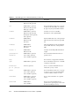
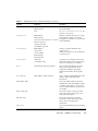
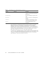
C.1
Shelf Manager Command-Line Interface
C.2
Shelf Manager CLI Commands
Index
B–8
C–2
C–3
Index–1
Contents
vii
viii
Sun Netra CP3250 Blade Server User’s Guide • April 2009
Figures
FIGURE 1-1
Netra CP3250 Blade Server (Front View)
1–4
FIGURE 1-2
Netra CP3250 Blade Server (Component Side View)
FIGURE 1-3
Netra CP3250 Blade Server in Shelf Enclosure
FIGURE 1-4
Netra CP3250 Blade Server, Backplane, and Relationship to ARTM
FIGURE 1-5
Netra CP3250 Blade Server Barcode Labeling
FIGURE 2-1
Installing a Netra CP32x0 ARTM
FIGURE 2-2
Injector/Ejector Latch and Locking Screw on the ARTM
FIGURE 2-3
Engaging the Netra CP3250 Blade Server Latch
FIGURE 2-4
Serial Port on the Netra CP3250 Blade Server
FIGURE 2-5
Locating DIMM Slots 2–20
FIGURE 2-6
Installing a DIMM
FIGURE 2-7
Removing a DIMM
FIGURE 2-8
Opening the Door to Access Compact Flash
FIGURE 2-9
Compact Flash Location
FIGURE 2-10
Removing an AMC Filler Panel
FIGURE 2-11
Installing an AMC 2–29
FIGURE 2-12
Jumper 2 in the Default Run Position
FIGURE 2-13
SW1 Default DIP Switch Settings
2–33
FIGURE 2-14
SW4 Default DIP Switch Settings
2–33
FIGURE 2-15
SW5 Default DIP Switch Settings
2–34
1–6
1–7
1–9
1–14
2–9
2–10
2–12
2–14
2–22
2–24
2–25
2–26
2–28
2–31
ix
FIGURE 2-16
Netra CP3250 Blade Server Front Panel
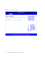
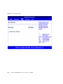
FIGURE A-1
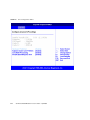
BIOS Main Menu
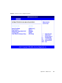
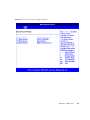
FIGURE A-2
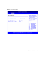
Advanced Configuration Menu
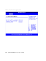
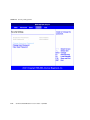
FIGURE A-3
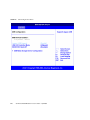
CPU Configuration Menu
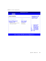
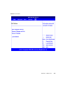
FIGURE A-4
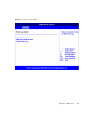
IDE Configuration Menu
FIGURE A-5
USB Configuration Menu
A–6
FIGURE A-6
Event Log Control Menu
A–7
FIGURE A-7
IPMI 2.0 Configuration Menu
FIGURE A-8
Remote Access Configuration Menu
FIGURE A-9
PCI Option ROM Configuration Menu
FIGURE A-10
Trusted Computing Menu
FIGURE A-11
Boot Settings Menu
FIGURE A-12
Boot Device Priority Configuration Menu
FIGURE A-13
Security Settings Menu
FIGURE A-14
Exit Menu A–15
FIGURE B-1
Ethernet RJ-45 Connector
FIGURE B-2
Front Panel USB Connector
FIGURE B-3
Front Panel Serial RJ-45 Connector
FIGURE B-4
Power Distribution Connector (Zone 1) P10
FIGURE B-5
Zone 2 Connector
B–8
FIGURE B-6
Zone 3 Connector
B–10
x
2–35
A–2
A–3
A–4
A–5
A–8
A–9
A–10
A–11
A–12
A–13
A–14
B–3
B–4
B–5
Sun Netra CP3250 Blade Server User’s Guide • April 2009
B–6
Tables
TABLE 1-1
I/O Configurations
1–10
TABLE 1-2
FRU ID Areas
TABLE 2-1
Local Area Network Information
TABLE 2-2
Netinstall Boot Device Table
TABLE 2-3
Extra MAC Addresses for Virtual LAN Configuration
TABLE 2-4
Pin Functions on Jumper 2
TABLE 5-1
BIOS Setup Screens Summary
TABLE 5-2
POST Options 5–9
TABLE B-1
Ethernet Port Connector Pin Assignments
TABLE B-2
USB Port Pin Assignments
TABLE B-3
Serial Port Mini DIN 8-pin Connector Pinouts
TABLE B-4
Power Distribution Connector Pin Assignments
TABLE B-5
Zone 2 Connector Pin Assignments
TABLE B-6
J30 Pin Connector Assignments
B–10
TABLE B-7
J31 Connector Pin Assignments
B–11
TABLE B-8
J32 Connector Pin Assignments
B–12
TABLE B-9
J33 Connector Pin Assignments
B–13
TABLE B-10
Zone 3 Signal Descriptions
TABLE C-1
Shelf Manager CLI Command Summary
1–15
2–5
2–15
2–16
2–31
5–3
B–3
B–4
B–5
B–6
B–8
B–14
C–3
xi
xii
Sun Netra CP3250 Blade Server User’s Guide • April 2009
Preface
The Sun Netra CP3250 Blade Server User’s Guide describes the hardware specifications,
function, and physical properties of the Sun Netra™ CP3250 blade server. It also
provides detailed information on the system firmware.
The Sun Netra CP3250 Blade Server User’s Guide is written for system integration
engineers, field applications and service engineers, and others involved in the
integration of this blade server into systems. This guide is written for personnel who
are familiar with the Solaris™ Operating System, the Linux operating systems and
Advanced Telecommunications Computing Architecture (ATCA) computing
environment.
How This Document Is Organized
Chapter 1 provides an overview of the Sun Netra CP3250 blade server.
Chapter 2 provides instructions on hardware installation.
Chapter 3 provides information on hardware architecture.
Chapter 4 provides information on the supported operating systems and on the Sun
Validation Test Suite (SunVTS™) software.
Chapter 5 provides information on the BIOS (Basic Input Output System).
Appendix A provides first-level and second-level BIOS menu illustrations.
Appendix B provides information on the Sun Netra CP3250 blade server physical
characteristics.
Appendix C provides a list of the most commonly used ShMM commands.
xiii
Using UNIX Commands
This document might not contain information about basic UNIX® commands and
procedures such as shutting down the system, booting the system, and configuring
devices. Refer to the following for this information:
■
Software documentation that you received with your system
■
Solaris™ Operating System documentation, which is at:
http://docs.sun.com/app/docs/prod/solaris
Shell Prompts
xiv
Shell
Prompt
C shell
machine-name%
C shell superuser
machine-name#
Bourne shell and Korn shell
$
Bourne shell and Korn shell superuser
#
Sun Netra CP3250 Blade Server User’s Guide • April 2009
Typographic Conventions
Typeface*
Meaning
Examples
AaBbCc123
The names of commands, files,
and directories; on-screen
computer output
Edit your.login file.
Use ls -a to list all files.
% You have mail.
AaBbCc123
What you type, when contrasted
with on-screen computer output
% su
Password:
AaBbCc123
Book titles, new words or terms,
words to be emphasized.
Replace command-line variables
with real names or values.
Read Chapter 6 in the User’s Guide.
These are called class options.
You must be superuser to do this.
To delete a file, type rm filename.
* The settings on your browser might differ from these settings.
Related Documentation
For additional information about the Sun Netra CP3250 blade server or the Netra
CP32x0 advanced rear transition module (ARTM), refer to the following documents
The following table lists the documentation for this product. The online
documentation is available at:
http://docs.sun.com/app/docs/prod/cp3250.brd#hic
Application
Title
Part Number
Format
Location
Installation
and Service
Sun Netra CP3250 Blade Server
User’s Guide (this manual)
820-5195
PDF,
HTML
Online
Pointer
Doclette
Netra CP3250 Blade Server Getting
Started Guide
820-5197
Printed,
PDF,
HTML
Shipkit
Preface
xv
Application
Title
Part Number
Format
Location
Late-breaking Netra CP3250 Blade Server Product
Information
Notes
820-5194
PDF,
HTML
Online
Safety
Information
Netra CP3250 Blade Server Safety
and Compliance Guide
820-5198
PDF,
HTML
Online
Safety
Information
Important Safety Information for
Sun Hardware Systems
816-7190
Printed
Shipkit
The following table lists the documentation that is related to this product.
.
Application
Title
Part Number
Format
Location
Installation and
Configuration
Sun Netra CP32x0 SAS Storage
Advanced Rear Transition Module,
Dual HD User’s Guide
820-3147
PDF,
HTML
Online
http://docs.sun.com/app/docs/prod/cp32x0.sas#hic
Installation and
Configuration
Sun Netra™ CP32x0 Quad GbE,
Dual Fibre Channel, Advanced Rear
Transition Module, User’s Guide
820-3148
PDF,
HTML
Online
http://docs.sun.com/app/docs/prod/cp32x0.4gbefc?l=en#hic
Installation and
Configuration
Sun Netra™ CP32x0 10GbE
Advanced Rear Transition Module,
Dual Port User’s Guide
820-3150
PDF,
HTML
Online
http://docs.sun.com/app/docs/prod/cp32x0.10gbee?l=en#hic
Documentation, Support, and Training
xvi
Sun Function
URL
Documentation
http://docs.sun.com/
Support
http://www.sun.com/support/
Training
http://www.sun.com/training/
Sun Netra CP3250 Blade Server User’s Guide • April 2009
Third-Party Web Sites
Sun is not responsible for the availability of third-party web sites mentioned in this
document. Sun does not endorse and is not responsible or liable for any content,
advertising, products, or other materials that are available on or through such sites
or resources. Sun will not be responsible or liable for any actual or alleged damage
or loss caused by or in connection with the use of or reliance on any such content,
goods, or services that are available on or through such sites or resources.
Sun Welcomes Your Comments
Sun is interested in improving its documentation and welcomes your comments and
suggestions. You can submit your comments by going to:
http://www.sun.com/hwdocs/feedback
Please include the title and part number of your document with your feedback:
Sun Netra CP3250 Blade Server User’s Guide, part number 820-5195.
Preface
xvii
xviii
Sun Netra CP3250 Blade Server User’s Guide • April 2009
CHAPTER
1
Overview
This chapter provides an overview of the features, configurations, and system
requirements of the Sun Netra CP3250 blade server.
This chapter contains the following sections:
■
Section 1.1, “Overview” on page 1-2
■
Section 1.2, “Features” on page 1-2
■
Section 1.3, “Physical Description” on page 1-4
■
Section 1.4, “System Configurations” on page 1-7
■
Section 1.5, “Hot-Swap Support” on page 1-11
■
Section 1.6, “System Components” on page 1-11
■
Section 1.7, “Technical Support and Warranty” on page 1-13
1-1
1.1
Overview
The Sun Netra CP3250 blade server is a dual-socket quad-core Intel-based ATCA
blade for high performance ATCA x86 applications in wireless infrastructure and
central office consolidation.
This blade server complies with the AdvancedTCA specification and is a new
addition to SUN's ATCA product family.
The ATCA standard comprises the PICMG 3.0, 3.1, 3.2, and 3.3 versions of the
standard. The Sun Netra CP3250 blade server complies with the following
specifications:
1.2
■
PICMG 3.0, the base specification that defines the mechanical, power distribution,
system management, data transport, and regulatory guidelines.
■
PICMG 3.1, which builds on the PICMG 3.0 base specification and on IEEE
802.3-2003.
Features
The blade server’s primary features are as follows:
1-2
■
ATCA card 322.25 mm x280 mm, 1.2 inch slot height
■
Two Harpertown Processor Sockets, QuadCore version @2.135 GHz and up to
40W per CPU
■
Intel San Clemente North Bridge and Intel ICH9R I/O controller hub
■
DDR2 (registered, with ECC) at 667 MHz, up to six modules/cards, up to 4 GB
per DIMM, in very-low-profile design (0.72 inch height)
■
Two 1000MBASE-T Ethernet base fabric (PICMG 3.0) interface ports (using
BCM5715C) from PCIe x4
■
Two 10 Gb XAUI Ethernet extended fabric (PICMG 3.1) interface ports (using Sun
Neptune) from PCIe x8
■
One AMC.1 Type 8S2E2 expansion slot (PCIe x8) supporting I/O expansion with
signaling to the advanced rear transition module (ARTM)
■
One Asynchronous serial port routed to front panel and ARTM from SuperIO
Sun Netra CP3250 Blade Server User’s Guide • April 2009
■
Dual USB 2.0/1.1 ports on front panel
■
One 10/100/1000MHBASE-T management port on front panel, with second
management LAN sent to ARTM (from BCM 5715C); these are not directly tied
into IPM controller.
■
SATA to EIDE master to support one Compact Flash Type II socket up to 16 GB of
user Flash. Socket is only accessible when blade is removed from chassis
■
Redundant BIOS, 8MB
■
Management support using on-board IPM controller (Renesas H8) that provides
dual IPMB bus. The IPMB bus is to be monitored by the shelf manager, providing
redundant IPMI channels
■
Rear I/O expansion/connectivity provided to an optional ARTM. Compatible
with Sun’s current ARTM architecture with upgrade capability to support PICMG
working group ARTM.0 standard (Zone 3 Interface)
■
SAS connectivity from ARTM to AMC slot
■
Contains TPM (Trusted Platform module) chip
■
225W delivered max power for the complete card (including 25W ARTM) via
dual, redundant -48 VDC nominal rails
■
Certified NEBS compliant in Sun’s Netra CT 900 system
Chapter 1
Overview
1-3
1.3
Physical Description
1.3.1
Front Panel Components
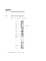
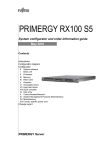
FIGURE 1-1
1-4
Netra CP3250 Blade Server (Front View)
Sun Netra CP3250 Blade Server User’s Guide • April 2009
Figure Legend
1
Locking screws
2
Latches
3
Out-of-service (OOS) LED
4
OK LED
5
AMC slot
6
10/100/1000 Ethernet management port
7
Serial port
8
USB port
9
Reset button
Chapter 1
Overview
1-5
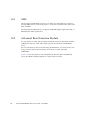
1.3.2
Blade Server Diagram
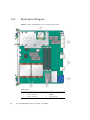
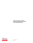
FIGURE 1-2
Netra CP3250 Blade Server (Component Side View)
Figure Legend
1-6
1
CF card slot
4
Zone 1 power connector
2
Zone 3 connectors
5
DIMMs
3
Zone 2 connectors
6
CPU heatsinks
Sun Netra CP3250 Blade Server User’s Guide • April 2009
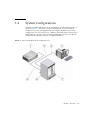
1.4
System Configurations
Sun Netra CP3250 blade servers can be installed into an ATCA shelf (chassis), as
shown in FIGURE 1-3. The blade servers can be deployed in various electrical
configurations to suit user requirements. For example, the blade server can be
configured to boot from a network as a diskless client with either a front panel or
ARTM network connection. The Sun Netra CP3250 blade server has an optional
Compact Flash card and connectors for additional memory.
FIGURE 1-3
Netra CP3250 Blade Server in Shelf Enclosure
Chapter 1
Overview
1-7
1.4.1
AMC
The Sun Netra CP3250 blade server has one AMC slot, with eight lanes of PCIe, to
provide additional I/O to the front panels or to the rear of the enclosure when used
with an ARTM.
The Sun Netra CP3250 blade server supports AMC mid-height, single wide cards, as
defined by the AMC specification.
1.4.2
Advanced Rear Transition Module
You can install one of the optional Netra CP32x0 advanced rear transition modules
(ARTMs) into the rear of the ATCA shelf, opposite the Sun Netra CP3250 blade
server.
For more information, refer to the following documentation: Sun Netra CP32x0 SAS
Storage Advanced Rear Transition Module, Dual HD User’s Guide (820-3147)
(ARTM-HD)
FIGURE 1-4 shows the physical relationship between the Sun Netra CP3250 blade
server, the ARTM, and the backplane in a typical ATCA system.
1-8
Sun Netra CP3250 Blade Server User’s Guide • April 2009
FIGURE 1-4
Netra CP3250 Blade Server, Backplane, and Relationship to ARTM
Note – When using the ARTM with the Sun Netra CP3250 blade server, use cables
of less than 10 meters in length for serial I/O ports.
Chapter 1
Overview
1-9
You can order a Netra CP32x0 ARTM, build a custom module, or buy one from an
IHV. You must set up a minimal set of I/O for a boot path for the host blade server
and for a path for console I/O to deliver commands and read blade server and
system status.
Possible boot and console configurations are described in TABLE 1-1. Sun
Microsystems provides the Sun Netra CP3250 blade server and, optionally, a
compatible Netra CP32x0 ARTM. The ARTM provides one 10/100/1000BASE-T per
second Ethernet RJ-45 port from the host to the rear of the system. This port can be
used to accomplish, optionally, a network boot as a diskless client. The other
configurations require IHV hardware.
I/O Configurations
TABLE 1-1
I/O
Hardware Required
Description
Ethernet
Netra CP32x0 ARTM, as an
option for rear access
The default boot path uses an Ethernet port; the blade server
runs in a diskless client configuration
SAS
Netra 146-GB hard disk and the Available with the optional Netra CP32x0 ARTM-HD or
Netra CP32x0 ARTM-HD
through an AMC with SAS capabilities. When the optional
ARTM is installed, connect to the drive(s) via SAS ports on the
ARTM.
Zone 3
ARTM
Zone 3
ARTM
Serial data
Sun Netra CP3250 blade server Serial port A on the front panel provides the path of the default
console I/O.
When an optional Netra CP32x0 ARTM is installed, the
Netra CP32x0 ARTM
module’s serial port A will become the path of the default
console I/O (FIGURE 1-4).
Serial data
Compact
Flash
1-10
IDE Compact Flash card
Sun Netra CP3250 blade server supports one, optional IDE
Compact Flash drive, either 8-Gbyte or 16-Gbyte, installed in a
Type II CF socket on the blade server.
Sun Netra CP3250 Blade Server User’s Guide • April 2009
1.5
Hot-Swap Support
Hot-swap support for inserting and extracting blade servers is provided in
accordance with the ATCA PICMG 3.0 and 3.1 standards.
Hot-swap of the CP3250, ARTM, and AMC is supported in the Netra CT 900 server.
1.6
System Components
This section contains the system-level hardware and software components, required
and optional, for the Sun Netra CP3250 blade server.
1.6.1
Required Hardware Components
The Sun Netra CP3250 blade server cannot be used as a stand-alone system. It is
designed to be used in an ATCA chassis for 8U boards. The minimum hardware
requirements needed to use the Sun Netra CP3250 blade server are:
■
ATCA system enclosure for 8U boards (includes shelf, backplane, hub/switch
board, shelf manager and power supply)
■
Console output device or serial terminal
■
Boot device (such as hard drive, network, or Compact Flash card)
■
Peripheral device for network access
■
IPMC (built in)
■
Cables for terminal and network connections
■
Netra CT 900 server fan tray upgrade kit (PN 594-4953-01). If you are installing
the Sun Netra CP3250 blade server in a Netra CT 900 server that has lower-speed
fan trays, you must upgrade the Netra CT 900 server fan trays to support the
additional cooling needs of the Sun Netra CP3250 blade server. For more
information on the Netra CT 900 server fan tray upgrade kit (PN 594-4953-01), see
the Netra CT 900 Server Upgrade Guide (820-3255).
Caution – You can damage the Sun Netra CP3250 blade server components if you
install the blade server in a chassis that does not provide sufficient cooling. For more
information, see Section 2.2.1.1, “Check Power, Thermal, Environmental, and Space
Requirements” on page 2-4.
Chapter 1
Overview
1-11
Note – Use only serial cables that are less than 10 meters in length.
1.6.2
Optional Hardware Components
Sun Microsystems provides the following items for customer order:
■
Compact Flash card
■
AMCs
■
Netra CP32x0 ARTM (optional)
The ARTM is optional and must be ordered separately from the Sun Netra
CP3250 blade server.
The optional ARTM enables rear system I/O access to the following:
■
■
Network
■
Boot device
■
Two hot-swappable SAS hard disk drives (optional)
■
Console terminal (FIGURE 1-3).
Sun Netra CP3240 switch (optional)
The Sun Netra CP3240 switch is capable of operating at 10 GbE, but is set by
default to operate at 1GbE. To use the switch at 10 GbE, perform a one-time
configuration procedure, available in the Sun Netra CP3x40 Switch Product Notes
(820-3260).
1.6.3
Software Components
The following OSs are certified for use on Sun Netra CP3250 blade server:
■
Solaris™ 10 (05/08) Operating System (Solaris OS)
■
WindRiver Linux 3.1
■
RedHat Linux 5.2
■
Windows 2003
Additional OSs are being tested and will be supported after they are certified.
Refer to the Netra CP3250 Blade Server Product Notes (820-5194) for more Solaris OS
information, including a list of any required Netra software patches and support for
subsequent versions of Solaris and other OSs. You can view and download the latest
version of the product notes at the following web site:
http://docs.sun.com
1-12
Sun Netra CP3250 Blade Server User’s Guide • April 2009
Additionally, VMware is a software component certified to work with the Sun Netra
CP3250 blade server. It is listed on VMware’s HCL at:
http://www.vmware.com/resources/compatibility/search.php?action=
search&deviceCategory=server&productId=1&keyBasic=
netra&maxDisplayRows=50&key=netra&release%5B%5D=-1&datePosted=
-1&stepping=&nsockets=&ncores=&max_mem=
1.7
Technical Support and Warranty
Should you have any technical questions or support issues that are not addressed in
the Sun Netra CP3250 blade server documentation set or on the technical support
web site, contact your local Sun Services representative. This hardware carries a
one-year return-to-depot warranty.
For customers in the U.S. or Canada, call 1-800-USA-4SUN (1-800-872-4786).
For customers in the rest of the world, please find the World Wide Solution Center
nearest you at the following web site:
http://www.sun.com/contact/services_solutions.jsp
When you call Sun Services, be sure to indicate if the Sun Netra CP3250 blade server
was purchased separately, and is not associated with a system. Please have the blade
server identification information ready. For proper identification of the blade server,
be prepared to give the representative the blade server part number, and serial
number.
1.7.1
Locating the Part Number and Serial Number
Information
The Sun Netra CP3250 blade server part number, serial number, revision number,
and media access control (MAC) address are printed on stickers located on the Sun
Netra CP3250 blade server (FIGURE 1-5).
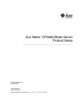
The Sun barcode label provides the following information:
■
Blade server serial number (for example, 1005LCB-07296R0912), which is on the
barcode label
The part number/dash/revision/date code label provides the following
information:
Chapter 1
Overview
1-13
■
Blade server part number (for example, 3753529), which is the first seven digits on
the part number label
■
Product dash number (for example, -01)
■
Revision number (for example, REV: 01)
The MAC address label contains the base MAC address for the blade server in
printed and barcode form. It is an orange label located on the Zone 1 connector.
FIGURE 1-5
Netra CP3250 Blade Server Barcode Labeling
Part number label
Serial number label
1.7.2
Viewing the Electronic Blade Server ID
Information
The Sun Netra CP3250 blade server can be electronically identified through its IPMI
FRU ID PROM, which is accessible through standard fru utilities.
The IPMI FRU ID PROM format follows the Intel Specification IPMI Platform
Management FRU Information Storage Definition, v1.0 Document, Revision 1.1,
September 27, 1999.
1-14
Sun Netra CP3250 Blade Server User’s Guide • April 2009
The IPMI FRU ID manufacturing records match Sun part number and serial number
labels on the product. For more information about part number and serial number
labels, see Section 1.7.1, “Locating the Part Number and Serial Number Information”
on page 1-13.
The IPMI FRU ID contains six FRU ID areas, which are defined in TABLE 1-2.
TABLE 1-2
FRU ID Areas
FRU Area
Description
COMMON
HEADER
Contains header and pointers to other FRUID sections and is used
by fru utility software
INTERNAL USE
AREA
Not present
CHASSIS INFO
AREA
Not present
BOARD INFO
AREA
Contains the manufacturing record without memory (FRU part
number) for the FRU level assembly of the blade server. This
assembly level is equivalent to the FRU replacement that is received
from Sun Service.
• Mfg Date/Time = (Date/Time of blade server assembly}
• Manufacturer = {manufacturer name)
• Product Name = CP3250
• Serial Number = XXXXXXX-XXXXXXXXXX (Sun 18-digit format)
• Part Number = 000000000PPPPPPPDDRR (Sun Part Number)
where 0 = Leading zeroes, P= Part Number, D=Dash, R=Rev
PRODUCT INFO
AREA
Contains manufacturing record for configured blade server with
memory. This assembly level includes the base blade server (FRU)
plus memory.
• Manufacturer = (manufacturer name)
• Product Name = CP3250
• Part/Model Number = 000000000PPPPPPPDDRR (Sun Part
Number) where 0 = Leading zeroes, P= Part Number, D=Dash, R=
Rev
• Product Version = XXXX (dash/rev)
• Serial Number = XXXXXXX-XXXXXXXXXX (Sun 18-digit format)
MULTIRECORD
INFO AREA
Sun Internal Use Only
Chapter 1
Overview
1-15
1-16
Sun Netra CP3250 Blade Server User’s Guide • April 2009
CHAPTER
2
Hardware Installation and Service
This chapter describes the Sun Netra CP3250 blade server hardware installation and
service procedures.
This chapter contains the following sections:
■
Section 2.1, “Safety and Tool Requirements” on page 2-2
■
Section 2.2, “Installing the Blade Server” on page 2-4
■
Section 2.3, “Service Procedures” on page 2-17
2-1
2.1
Safety and Tool Requirements
2.1.1
Equipment and Operator Safety
Refer to the Important Safety Information for Sun Hardware Systems (816-7190) for
general safety information and to the Netra CP3250 Blade Server Safety and Compliance
Guide (820-5198) for specific safety information.
Read the following safety statements that are specific to the Sun Netra CP3250 blade
server carefully before you install or remove any part of the system.
Caution – Depending on the particular chassis design, operations with open
equipment enclosures can expose the installer to hazardous voltages with a
consequent danger of electric shock. Ensure that line power to the equipment is
disconnected during operations that make high voltage conductors accessible.
The installer must be familiar with commonly accepted procedures for integrating
electronic systems and the general practice of Sun systems integration and
administration. Although parts of these systems are designed for hot-swap
operation, other components must not be subjected to such stresses. Work with
power connected to a shelf only when necessary, and follow these installation
procedures to avoid equipment damage.
This equipment is sensitive to damage from electrostatic discharge (ESD) from
clothing and other materials. Use the following antistatic measures during an
installation:
2-2
■
If possible, disconnect line power from the shelf when servicing a system or
installing a hardware upgrade. If the shelf cannot be placed on a grounded
antistatic mat, connect a grounding strap between the facility electrical input
ground (usually connected to the shelf) and facility electrical service ground.
■
Use an antistatic wrist strap when performing the following tasks:
■
Removing a blade server from its antistatic bag
■
Connecting or disconnecting blade servers or peripherals
Sun Netra CP3250 Blade Server User’s Guide • April 2009
The other end of the antistatic wrist strap lead should be connected to one of the
following:
■
A ground mat
■
The chassis metal as a ground
The grounded mat or the chassis must be connected to a facility ground to
prevent a floating ground.
2.1.2
■
Keep blade servers in the antistatic bags until they are needed.
■
Remove a blade server from its antistatic bag only when wearing a properly
connected ground strap.
■
Place circuit blade servers that are out of their antistatic bags on an antistatic mat
if one is available and the mat is grounded to a facility electrical service ground.
Do not place blade servers on top of an antistatic bag unless the outside of the bag
also has antistatic protective properties.
Materials and Tools Required
The tools required for installation and service are as follows:
■
Phillips screwdrivers: No. 1 (required), No. 2 (optional)
■
Antistatic wrist strap
■
Terminal console
■
Serial cable of less than 10 meters in length to connect the Sun Netra CP3250
blade server with a system console
Refer to Section 1.6, “System Components” on page 1-11 for information on
hardware requirements.
Chapter 2
Hardware Installation and Service
2-3
2.2
Installing the Blade Server
2.2.1
Preparing for the Installation
Prepare for installation by reading and performing the following steps.
1. Become familiar with the contents of the documentation referenced in the steps.
2. Verify that all listed hardware and software are available (see Section 1.6, “System
Components” on page 1-11).
3. Check power, thermal, environmental, and space requirements (see
Section 2.2.1.1, “Check Power, Thermal, Environmental, and Space Requirements”
on page 2-4).
4. Verify that local area network (LAN) preparations are completed (see
Section 2.2.1.2, “Local Network IP Addresses and Host Names Worksheet” on
page 2-5).
5. Ensure that the host names and their network IP addresses are allocated and
registered at the site. Record this information in TABLE 2-1.
2.2.1.1
Check Power, Thermal, Environmental, and Space
Requirements
Observe that your environment meets the following requirements:
■
Your enclosure specifications can support the sum of the specified maximum
blade server power loads. (See Section B.2, “Power and Thermal Metrics” on
page B-2).
■
Facility power loading specifications can support the rack or enclosure
requirements.
■
Your enclosure specifications can support the cooling airflow requirements.
The Sun Netra CP3250 blade server fits into a standard ATCA shelf. If your
installation requirements are different, contact your field applications engineer.
2-4
Sun Netra CP3250 Blade Server User’s Guide • April 2009
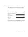
2.2.1.2
Local Network IP Addresses and Host Names Worksheet
Collect the information listed in TABLE 2-1 to connect hosts to the LAN. Ask your
network administrator for help, if necessary. This information is not needed for a
stand-alone installation.
TABLE 2-1
Local Area Network Information
Information Needed
Your Information
IP address* and host name for each Sun
Netra CP3250 blade server client
Domain name
Type of name service and corresponding
name server names and IP addresses—for
example DNS and NIS (or NIS+)
Subnet mask
Gateway router IP address
Network File System (NFS) server names
and IP addresses
Web server URL
* Local IP addresses are not needed if they are assigned by a network Dynamic Host Configuration Protocol
(DHCP) server.
You might need the MAC (Ethernet) addresses of the local hosts to make name
server database entries. You can see the MAC address in the console output while
booting the blade server. You can also find it on the barcode label on the node blade
server (see Section 1.7.1, “Locating the Part Number and Serial Number
Information” on page 1-13).
Chapter 2
Hardware Installation and Service
2-5
2.2.1.3
Installation Procedure Summary
This section summarizes the high-level procedures that are required to install the
Sun Netra CP3250 blade server. Ensure that you are familiar with the information in
Section 2.2.2, “Configuring the Hardware” on page 2-6 through the end of Chapter 2
before installing the blade server.
The process to set up and configure a Sun Netra CP3250 blade server in a system
includes the following procedures:
1. Configuring the blade server’s physical hardware.
For example, install the AMC and set switches, as necessary (Section 2.2.2,
“Configuring the Hardware” on page 2-6).
2. Physically installing the advanced rear transition module (ARTM) as necessary
(Section 2.2.3.1, “Installing an Advanced Rear Transition Module (ARTM)” on
page 2-8).
3. Physically installing the Sun Netra CP3250 blade server, and any peripheral
boards into the ATCA shelf Section 2.2.3, “Installing the Netra CP3250 Blade
Server in an ATCA Shelf” on page 2-8).
4. Connecting the nodes to a local network. (Section 2.2.4, “Connecting External I/O
Cables” on page 2-13).
5. Downloading and installing SunVTS (Section 4.1, “Operating Systems” on
page 4-2), if you are running the Solaris Operating System on the Sun Netra
CP3250 blade server and want to verify system integrity.
2.2.2
Configuring the Hardware
This section lists hardware installation and settings that might apply to your blade
server configuration. Read and perform the procedures, as necessary, before
installing the Sun Netra CP3250 blade server into the ATCA shelf.
2.2.2.1
Verify Chassis Fan Tray Upgrade
Caution – The Netra CT 900 server fan tray upgrade kit (594-4953) must be
installed in the chassis before the Sun Netra CP3250 blade server is installed. This
fan tray upgrade is required to provide adequate cooling and prevent the system
from overheating or shutting down due to an over temperature condition that can
occur with the older or mismatched fan trays.
2-6
Sun Netra CP3250 Blade Server User’s Guide • April 2009
●
To verify if the fan tray upgrade is installed on a Netra CT 900 server, log into
the Shelf Manager and issue the following command for fan trays 1,2, and 3:
# clia fruinfo fan_tray 1 | grep "Product Part"
If the “Product Part/Model Number” is 370-7764-xx, the fan trays must be replaced
with high-speed fan trays. Refer to the Netra CT 900 Server Upgrade Guide (820-3255)
for more information.
If the “Product Part/Model Number” is 371-3033-xx or newer, an upgraded fan tray
is already installed.
2.2.2.2
Installing Optional Components
Use the following table to locate your options and installation instructions.
2.2.2.3
DIMMs
“DIMM Requirements” on page 2-19
“Installing a DDR2 DIMM” on page 2-21
Compact Flash card
“Installing the Optional Compact Flash Card” on page 2-24
AMC
“Compact Flash Location” on page 2-26
Configuring the Advanced Rear Transition Module (ARTM)
If you are using one of the Netra advanced rear transition modules (ARTMs), refer to
the documentation: Netra CP32x0 SAS Storage Advanced Rear Transition Module, Dual
HD User’s Guide (820-3147) (ARTM-HD)
See Section B.3, “Connectors and Pinouts” on page B-2 for detailed connector pin
assignments for the Sun Netra CP3250 blade server.
Chapter 2
Hardware Installation and Service
2-7
2.2.3
Installing the Netra CP3250 Blade Server in an
ATCA Shelf
If you install the Sun Netra CP3250 blade server with an ARTM, the ARTM must be
installed first.
Note – Slots 1 through 6 and 9 through 14 are available for Sun Netra CP3250 blade
servers. Slots 7 and 8 are reserved for the switch card.
2.2.3.1
Installing an Advanced Rear Transition Module (ARTM)
A compatible ARTM must be used with the Sun Netra CP3250 blade server for rear
I/O access. The ARTM enables access to the network, a boot device, and a console
terminal. You can use one of the Netra CP32x0 ARTMs or you can design your own
ARTM-compatible transition module. For more information, see Section 1.4.2,
“Advanced Rear Transition Module” on page 1-8.
1. Verify that you have taken the necessary antistatic precautions.
See Section 2.1.1, “Equipment and Operator Safety” on page 2-2.
2. From the rear of the system, choose the corresponding slot for the ARTM.
The rear transition module must be installed, inline, behind a compatible Netra
blade server.
For example, if the Sun Netra CP3250 blade server will be installed in slot 3, the
corresponding rear transition module must be installed at the back of the system
in slot 3 (FIGURE 2-1). If you do not install the rear transition module and the Sun
Netra CP3250 blade server in corresponding slots, the system will recognize the
Sun Netra CP3250 blade server and not the rear transition module.
Note – Slots 1 through 6 and 9 through 14 are available for Sun Netra CP3250 blade
servers. Slots 7 and 8 are reserved for the switch card.
2-8
Sun Netra CP3250 Blade Server User’s Guide • April 2009
FIGURE 2-1
Installing a Netra CP32x0 ARTM
3. Remove the slot filler panel from the selected slot, if necessary.
4. Retrieve the advanced rear transition module (ARTM) from the ship kit.
5. Prepare the rear transition module by opening the injector/ejector latch at the
top of the module (FIGURE 2-2).
Chapter 2
Hardware Installation and Service
2-9
FIGURE 2-2
Injector/Ejector Latch and Locking Screw on the ARTM
6. Carefully align the edges of the ARTM with the card guides in the appropriate
slot.
Look into the enclosure to verify correct alignment of the rails in the guides.
7. Keep the ARTM aligned in the guides, and slide the module in until the
injector/ejector latches engage the card cage.
8. Push the ARTM into the backplane connectors, and close the latch.
9. Tighten the locking screws to ensure that the module is secured into the ATCA
shelf.
2-10
Sun Netra CP3250 Blade Server User’s Guide • April 2009
10. Install the Sun Netra CP3250 blade server into the front of the ATCA shelf in
the corresponding slot.
See Section 2.2.3.2, “Installing the Blade Server Into the Shelf” on page 2-11 for
instructions.
2.2.3.2
Installing the Blade Server Into the Shelf
Note – You can install the Sun Netra CP3250 blade server in any available slot in the
ATCA shelf except for slots 7 and 8.
1. If you have installed an advanced rear transition module (ARTM), go to the
front of the system and locate the corresponding slot number of the ARTM.
2. Remove the filler panel from the blade server slot, if necessary.
The filler panel is secured to the card cage using two screws, one at the top of the
filler panel, the other at the bottom. Store the filler panel in a safe place; you
might need to use it again if you remove a blade server for an extended time.
3. Prepare the Sun Netra CP3250 blade server by opening the injector/ejector
latches.
4. Carefully align the edges of the blade server with the guides in the appropriate
slot.
Look into the enclosure to verify correct alignment of the rails in the guides.
5. Keep the blade server aligned in the guides and slide the blade server in until
the injector/ejector latches engage the card cage.
6. Push the blade server slightly into the backplane connectors and close the
latches to seat the blade server in the connectors (FIGURE 2-3).
Push the upper latch lever to engage the blade server. When the upper and lower
levers are engaged properly, the blue Hot-Swap LED blinks while the blade server
is initializing. The blue LED turns off and the green OK LED lights when the
blade server is ready for use.
Note – If the hot-swap LED does not light, then wiggle and push the latch so it
engages the hot-swap switch.
Chapter 2
Hardware Installation and Service
2-11
FIGURE 2-3
Engaging the Netra CP3250 Blade Server Latch
7. Tighten the locking screws and the top and the bottom of the Sun Netra CP3250
blade server to ensure that it is secured to the ATCA shelf (FIGURE 2-2).
The blade server is now completely installed and will power on automatically.
8. Configure the switches accordingly as described in Section 4.4, “Configuring
Sun Netra CP3250 blade server For 1 GbE or 10 GbE Switches” on page 4-4.
2-12
Sun Netra CP3250 Blade Server User’s Guide • April 2009
2.2.4
Connecting External I/O Cables
Front panel ports are typically used for maintenance and troubleshooting purposes
in installed and running systems. External I/O cables are connected to the Sun Netra
CP3250 blade server or to the Netra CP32x0 rear transition module when a rear
transition module is used.
To connect each of these following cables:
2.2.4.1
■
For Ethernet connections, Category 5e or better, network cable is required.
Connect one end of the Ethernet cable to a suitable 10/100/1000 MBASE-T
Ethernet switch and the other end to one of the Ethernet ports on the Sun Netra
CP3250 blade server or the Netra CP32x0 ARTM.
■
Attach asynchronous serial I/O cables from serial communication devices to the
RJ-45 serial ports on the Sun Netra CP3250 blade server or Netra CP32x0 ARTM.
Connecting Cables to a System Console Running the Solaris
OS
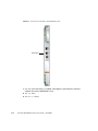
1. Connect a RJ-45 style serial cable to the serial console port on the front panel of
the Sun Netra CP3250 blade server (FIGURE 2-4) or the Netra CP32x0 rear
transition module.
Serial access (both front and rear) is through the same serial interface controller. If
both ports are connected at the same time, console input and output can be
performed through both, however, this configuration is not recommended. If both
access interfaces are not connected at the same time, console input/output can be
performed through NetConsole session via the ShMM.
2. Connect the other end of the serial cable to the serial port of the system serving
as the serial console.
Chapter 2
Hardware Installation and Service
2-13
FIGURE 2-4
Serial Port on the Netra CP3250 Blade Server
Serial port
3. Use one of the following to establish a full-duplex serial terminal connection
with the Sun Netra CP3250 blade server:
2-14
■
The tip utility
■
The minicom utility
Sun Netra CP3250 Blade Server User’s Guide • April 2009
■
A telnet utility (Connect to the proper port on a Network Terminal Server to
which the Sun Netra CP3250 blade server is connected.)
■
Another suitable serial communications program on the system console
For example, if you are using a UNIX system as the system console, at the UNIX
prompt in a command tool or shell tool, or serial port A, type:
# tip -9600 /dev/ttya
2.2.4.2
Connecting Cables to the System Console Not Running the
Solaris OS
1. Connect a serial cable to the serial console port on the front panel of the Sun
Netra CP3250 blade server (FIGURE 2-4) or the Netra CP32x0 rear transition
module.
2. Connect the other end of the serial cable to the serial port of the system serving
as the system console.
3. Set the serial communications settings to 9600 baud, 8 bit, 1 stop bit, no parity,
and no handshake.
2.2.4.3
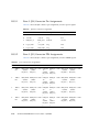
Netinstall Boot Device Map
TABLE 2-2 provides a map of netinstall boot devices. You may need this information
to understand which MAC address is associated with the system IP address on the install
server.
For example, the Base Fabric interface is connected to the switch model-number in
slot 8 of the ATCA shelf. To install to this device, select the xxx Ethernet interface
from the BIOS setup menus.
TABLE 2-2
Netinstall Boot Device Table
MAC Address
Solaris
Device
Hardware
Device
00:14:4f:xx.yy.zz+0
bge0
(BMC5715C)
Base Fabric 0
Slot 7
00:14:4f:xx.yy.zz+1
bge1
(BMC5715C)
Base Fabric 1
Slot 8
00:14:4f:xx.yy.zz+2
bge2
(MCP55)and
(BCM5715C)
mgtA (front panel)
00:14:4f:xx.yy.zz+3
bge3
(MCP55)and
(BCM5715C)
mgtB (rear panel)
Connects to...
Chapter 2
Switch Slot
Connection
Hardware Installation and Service
2-15
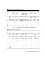
Netinstall Boot Device Table (Continued)
TABLE 2-2
MAC Address
Solaris
Device
Hardware
Device
00:14:4f:xx.yy.zz+4
nxge0
(Sun 10 GbE
Extended Fabric 0
Multithreaded
Networking
Technolgy 10 GB)
Slot 7
0:14:4f.xx.xn+5
nxge1
(Sun 10 GbE
Extended Fabric 1
Multithreaded
Networking
Technolgy 10 GB)
Slot 8
0:14:4f.xx.xn+6
nxge2
(Sun 10 GbE
Multithreaded
Networking
Technolgy 1 GB)
AMC and ARTM
0:14:4f.xx.xn+7
nxge3
(Sun 10 GbE
Multithreaded
Networking
Technolgy 1 GB)
AMC and ARTM
Connects to...
Switch Slot
Connection
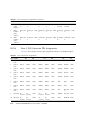
The Sun Netra CP3250 blade server supports virtual LAN configuration for the Sun
10 GbE Multithreaded Networking Technolgy ports (MAC addresses 4, 5, 6, and 7).
When configured, the virtual LAN feature enables the assignment of multiple MAC
address to one port. TABLE 2-3 lists the extra MAC addresses available for the Sun 10
GbE Multithreaded Networking Technolgy ports.
TABLE 2-3
2-16
Extra MAC Addresses for Virtual LAN Configuration
Primary MAC Address
Additional MAC Addresses
0:14:4f.xx.xn+4
0:14:4f.xx.xn+8
0:14:4f.xx.xn+5
0:14:4f.xx.xn+15 through 0:14:4f.xx.xn+21
0:14:4f.xx.xn+6
0:14:4f.xx.xn+22 through 0:14:4f.xx.xn+28
0:14:4f.xx.xn+7
0:14:4f.xx.xn+29 through 0:14:4f.xx.xn+35
Sun Netra CP3250 Blade Server User’s Guide • April 2009
through 0:14:4f.xx.xn+14
2.3
Service Procedures
2.3.1
Hot-Swapping the Netra CP3250 Blade Server
You can remove the Sun Netra CP3250 blade server without powering off the entire
chassis by performing these steps.
1. Power off the blade server.
See Section 2.3.2, “Powering Off the Netra CP3250 Blade Server” on page 2-17.
2. Remove the blade server.
See Section 2.3.3, “Removing the Netra CP3250 Blade Server” on page 2-18.
2.3.2
Powering Off the Netra CP3250 Blade Server
1. Shut down the operating system.
Log in and shut down any OS operating on the blade server or its companion
ARTM.
2. Deactivate the blade server.
Log in to the shelf manager and deactivate the blade server in the target slot.
For example, to shut down the blade server in slot 3, log in to the shelf manager
and type:
# clia deactivate board 3
Wait for the blue Hot-Swap LED to light steadily before removing the blade
server.
Chapter 2
Hardware Installation and Service
2-17
2.3.3
Removing the Netra CP3250 Blade Server
1. Power off the Sun Netra CP3250 blade server.
Use the instructions in Section 2.3.2, “Powering Off the Netra CP3250 Blade
Server” on page 2-17.
2. If installed, remove all cables from the front of the Sun Netra CP3250 blade
server.
3. Loosen the locking screws to release the blade server from the ATCA shelf.
4. When the blue Hot-Swap LED lights steadily, release the upper latch and the
lower latch at the same time to unseat the blade server from the connectors.
5. Remove the blade server from the ATCA shelf and place the blade server on an
antistatic mat.
2.3.4
Powering On the System
Sun Netra CP3250 blade servers are powered on automatically via the H8 BMC
when you install the blade server into a slot in the ATCA shelf. Once installed, the
blade server sequences through power-on states until it is fully powered on.
2.3.5
Automatic Power-Off Events
A power-off sequence is initiated either by a request from the shelf manager or a
fault condition. The Sun Netra CP3250 blade server shuts down to standby power
mode when the following upper critical threshold conditions are met:
■
Detection of DC input (both -48V A and -48V B) drop for more than 5ms
■
Processor thermal trip drops to standby mode
Thermal trip of DC brick turns off all local power (standby included)
2-18
Sun Netra CP3250 Blade Server User’s Guide • April 2009
2.3.6
Servicing DIMMs
2.3.6.1
DIMM Requirements
The Sun Netra CP3250 blade server supports a total of six DIMMs and the maximum
memory capacity of 24 GB (using four 4 GB DIMMs). The Sun Netra CP3250 blade
server accommodates the following DIMMs and configurations:
■
Up to six standard DDR2 SDRAM registered/ECC DIMMs
■
DIMMs must be installed in matching pairs
■
2 GB and 4 GB DDR2 modules are supported
■
Maximum of 24 GB in six slots
The Sun Netra CP3250 blade server supports DIMMs that have the following
characteristics:
■
A 144-bit wide data bus DDR2 interface (2x64-bit data + 2x8-bit ECC)
■
DDR2 DIMM: 4.4 - 7.0 watts (1.8 V)
■
Very low profile (VLP) with a maximum height of 0.72 inch (18.3 mm)
Chapter 2
Hardware Installation and Service
2-19
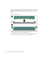
FIGURE 2-5
Locating DIMM Slots
Populate DIMMs in matching pairs, starting with Pair 0, then adding Pair 1, then
Pair 2.
There are two channels, Channel A and Channel B. DIMMs are identified as A0, B0,
A1, B1, A2, and B2. Where Pair 0 would be A0 and B0, and so on.
2-20
Sun Netra CP3250 Blade Server User’s Guide • April 2009
2.3.6.2
Installing a DDR2 DIMM
The following procedure provides a general guide for installing additional memory.
However, for specific directions on installing DIMMs on the Sun Netra CP3250 blade
server, refer to the documentation that shipped with the DIMMs.
1. Access the blade server by performing one of the following procedures:
■
If the Sun Netra CP3250 blade server is installed in an ATCA shelf, remove the
blade server from the shelf as explained in Section 2.3.3, “Removing the Netra
CP3250 Blade Server” on page 2-18.
■
Remove the Sun Netra CP3250 blade server from its antistatic envelope and place
it on an ESD mat near the ATCA shelf.
2. Take antistatic precautions: Attach and electrically ground the wrist strap.
Caution – Always wear a grounded antistatic wrist strap when handling DIMMs.
3. Locate the DIMM connectors on the Sun Netra CP3250 blade server.
Select the connectors where you will install the DIMM. See FIGURE 2-5 for DIMM
slot locations.
Caution – Do not remove the DIMM from its antistatic container until you are
ready to install the DIMM on the Sun Netra CP3250 blade server. Handle the DIMM
only by its edges. Do not touch DIMM components or metal parts. Always wear a
grounded antistatic wrist strap when handling DIMM.
4. Remove the DIMM from its protective packaging, holding the module only by
the edges.
Note – Before installing a replacement DIMM, verify that the new DIMM is the
same size as its paired DIMM.
5. Holding the DIMM upright to the blade server, insert the bottom edge of the
DIMM into the bottom of the slot’s hinge-style connector (FIGURE 2-6).
Caution – Evenly engage the DIMM in its hinge-style slot; uneven contact can
cause shorts that will damage the Sun Netra CP3250 blade server. Do not rock the
DIMM into place. Ensure that all contacts engage at the same time. You will feel or
hear a click when the DIMM properly seats in the connector.
Chapter 2
Hardware Installation and Service
2-21
The socket and module are both keyed, which means that the DIMM can be installed
only one way. With even pressure, push simultaneously on both upper corners of the
DIMM until its bottom edge (the edge with the gold fingers) is firmly seated in the
connector.
FIGURE 2-6
Installing a DIMM
6. Press the top edge of the DIMM toward the blade server until the retainer clips
click into place in the notches on the DIMM sides (FIGURE 2-6).
The small metal retainer clips on each side of the DIMM slot are spring-loaded, and
they should click into place in the notches on the sides of the DIMM.
2-22
Sun Netra CP3250 Blade Server User’s Guide • April 2009
2.3.6.3
Removing a DDR2 DIMM
If you are returning the DIMM or the blade server for service, or if you are replacing
a DIMM with another DIMM, remove the DIMM from the Sun Netra CP3250 blade
server.
Note – Safely store the original factory-shipped DIMM and related DIMM
packaging. Store any removed DIMM in the new DIMM packaging.
To remove a DIMM from the Sun Netra CP3250 blade server, perform the following
steps:
1. Access the blade server by performing one of the following procedures:
■
If the Sun Netra CP3250 blade server is installed in an ATCA shelf, remove the
blade server from the shelf as explained in Section 2.3.3, “Removing the Netra
CP3250 Blade Server” on page 2-18.
■
Remove the Sun Netra CP3250 blade server from its antistatic envelope and place
it on an ESD mat near the ATCA shelf.
If an ESD mat is not available, you can place the blade server on the antistatic
envelope in which it was packaged.
Caution – Do not place blade servers on top of an antistatic bag unless the outside
of the bag also has antistatic protective properties.
2. Take antistatic precautions: Attach and electrically ground the wrist strap.
Caution – Always wear a grounded antistatic wrist strap when handling DIMMs.
3. Simultaneously pull both spring retainer clips outward from the slot for the
DIMM you want to remove.
4. Grasp the DIMM by the edges, and carefully pull it out of its connector.
Place it in an antistatic bag.
Chapter 2
Hardware Installation and Service
2-23
FIGURE 2-7
Removing a DIMM
5. If you are replacing the DIMM you removed with a new DIMM, install it as
described in Section 2.3.6.2, “Installing a DDR2 DIMM” on page 2-21.
2.3.7
Installing the Optional Compact Flash Card
An IDE Compact Flash card can be installed on the Sun Netra CP3250 blade server.
The Compact Flash card is not hot-swappable, and there is no access to the Compact
Flash card once the Sun Netra CP3250 blade server is installed in an ATCA shelf.
1. Access the blade server by performing one of the following procedures:
■
If the Sun Netra CP3250 blade server is installed in an ATCA shelf, remove the
blade server from the shelf as explained in Section 2.3.3, “Removing the Netra
CP3250 Blade Server” on page 2-18.
■
Remove the Sun Netra CP3250 blade server from its antistatic envelope and place
it on an ESD mat near the ATCA shelf.
If an ESD mat is not available, you can place the blade server on the antistatic
envelope in which it was packaged.
Caution – Do not place blade servers on top of an antistatic bag unless the outside
of the bag also has antistatic protective properties.
2-24
Sun Netra CP3250 Blade Server User’s Guide • April 2009
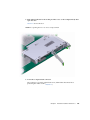
2. Push where indicated on door that provides access to the Compact Flash, then
open the door.
FIGURE 2-8 shows the door.
FIGURE 2-8
Opening the Door to Access Compact Flash
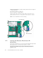
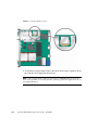
3. Locate the Compact Flash connector.
The connector is located on the blade server, behind the sheet metal door
protecting the AMC slot B1 (FIGURE 2-9).
Chapter 2
Hardware Installation and Service
2-25
FIGURE 2-9
Compact Flash Location
4. To install the Compact Flash card, use the arrow on the card as a guide to insert
the card into the Compact Flash connector.
Note – Sun Compact Flash cards have a life time of 2,000,000 write/erase cycles.
Users are responsible for ensuring that the operating system and applications do not
exceed this limitation.
2-26
Sun Netra CP3250 Blade Server User’s Guide • April 2009
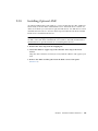
2.3.8
Installing Optional AMC
An Advanced Mezzanine card (AMC) is a card or module that provides additional
functionality to the Sun Netra CP3250 blade server. The blade server contains one
AMC slot in which you can install an optional AMC device. An AMC device can be
installed and removed via a cutout in the front panel while the Sun Netra CP3250
blade server is installed in the chassis.
Note – The following procedure provides a general set of instructions for installing
an AMC on the Sun Netra CP3250 blade server. Refer to the AMC manufacturer’s
documentation for specific instructions on installing these devices.
1. Retrieve the wrist strap from the shipping kit.
2. Attach the adhesive copper strip of the antistatic wrist strap to the metal
chassis.
Wrap the other end twice around your wrist, with the adhesive side against your
skin.
3. Remove the AMC slot filler panel from the blade server’s front panel
(FIGURE 2-10).
Chapter 2
Hardware Installation and Service
2-27
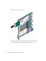
FIGURE 2-10
Removing an AMC Filler Panel
4. Retrieve the AMC from its shipping kit and place it on an antistatic surface.
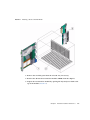
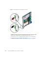
5. Insert the AMC through the cutout and into the AMC slot (FIGURE 2-11).
2-28
Sun Netra CP3250 Blade Server User’s Guide • April 2009
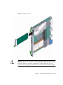
FIGURE 2-11
Installing an AMC
Caution – Do not use excessive force when installing the AMC into the slot. You
might damage the AMC connector on the Sun Netra CP3250 blade server, causing
permanent damage to the AMC or the blade server. If the AMC does not seat
properly when you apply even pressure, remove the AMC and carefully reinstall it.
Chapter 2
Hardware Installation and Service
2-29
6. Carefully push the AMC into the AMC connector.
7. Refer to the AMC documentation for software and cabling installation
instructions.
2.3.9
Adding or Replacing the Battery
The Sun Netra CP3250 blade server does not ship with the battery. If you want
CMOS settings to be preserved in the event of power loss, obtain and install the
battery.
The battery must be type CR1632, with a minimum of 4ma abnormal charging
current rating (for example; a Renata CR1632).
Caution – Risk of explosion if the battery is replaced by an incorrect type. Dispose
of used batteries properly in accordance with manufacturer’s instructions and local
regulations.
To install the battery:
1. Remove the old battery, if necessary.
2. Slide the new battery into the holder with the side labeled “+” facing up.
2-30
Sun Netra CP3250 Blade Server User’s Guide • April 2009
2.3.10
Changing Jumper Settings
Jumpers and their switches are located near the heatsink on the blade server.
2.3.10.1
Clearing the CMOS Setting Using Jumper 2
Reset jumper 2 to clear the CMOS settings, which restores the default BIOS settings.
Jumper 2 is shown in FIGURE 2-12. The jumper housing should be stored in the P2/P3
position, which is the run position.
FIGURE 2-12
Jumper 2 in the Default Run Position
TABLE 2-4 provides information on the pin functions on jumper 2.
TABLE 2-4
Pin Functions on Jumper 2
Pin Number
Purpose
Pin 1
Battery Feed
Pin 2
VCC_RTC (destination for battery
power)
Pin 3
BATT_CLR (resistor to GND, used to
drain capacitive charge and clear the
CMOS memory)
Chapter 2
Hardware Installation and Service
2-31
To reset the jumper and return the CMOS settings to the default settings, perform
the following steps:
1. Remove the jumper housing from the run position (P2/32) and move it to the
reset position (P1/P2).
2. Wait at least one second for the CMOS settings to reset and then move the
jumper housing back to the run position (FIGURE 2-12).
3. Reinstall the blade server.
Use the procedure in Section 2.2.3.2, “Installing the Blade Server Into the Shelf”
on page 2-11.
Note – The blade server will operate normally only when the jumper housing is in
the run position.
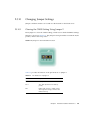
2.3.10.2
Changing the OOS LED Color Using Jumper 13
The color of the Out-of-service (OOS) LED can be set to red or amber by moving
jumper 13 to the appropriate position. Amber is the default color for the OOS LED.
To change the Jumper 13 position to display a red OOS LED:
1. Remove the jumper housing from the default (amber) position (P2/P3) and
move it to the red position (P1/P2).
2. Reinstall the blade server.
Use the procedure in Section 2.2.3.2, “Installing the Blade Server Into the Shelf” on
page 2-11.
2-32
Sun Netra CP3250 Blade Server User’s Guide • April 2009
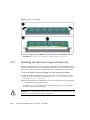
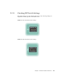
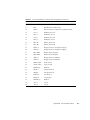
2.3.11
Checking DIP Switch Settings
DIP switch settings are set by default at the factory. The following settings are
required for normal operation of the blade server.
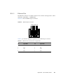
FIGURE 2-13
SW1 Default DIP Switch Settings
FIGURE 2-14
SW4 Default DIP Switch Settings
Chapter 2
Hardware Installation and Service
2-33
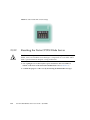
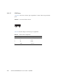
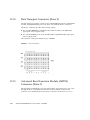
FIGURE 2-15
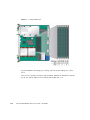
2.3.12
SW5 Default DIP Switch Settings
Resetting the Netra CP3250 Blade Server
Caution – Do not operate the ATCA shelf without all fans, component heatsinks, air
baffles, and covers installed. Severe damage to components can occur if the ATCA
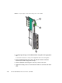
shelf is operated without adequate cooling mechanisms.
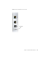
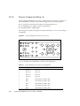
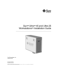
1. Use a spudger tool or other stylus to press and release the recessed Reset
button on the front of the Sun Netra CP3250 blade server (FIGURE 2-16).
2. Confirm the progress of the reset by monitoring the BIOS POST messages.
2-34
Sun Netra CP3250 Blade Server User’s Guide • April 2009
FIGURE 2-16
Netra CP3250 Blade Server Front Panel
Reset button
Chapter 2
Hardware Installation and Service
2-35
2-36
Sun Netra CP3250 Blade Server User’s Guide • April 2009
CHAPTER
3
Hardware Architecture
This chapter describes the hardware components and architecture of the Sun Netra
CP3250 blade server.
This chapter contains the following sections:
■
Section 3.1, “Block Diagram” on page 3-2
■
Section 3.2, “Intel Processors” on page 3-3
■
Section 3.3, “Intel San Clemente MCH” on page 3-3
■
Section 3.4, “Memory” on page 3-4
■
Section 3.5, “Networking and I/O” on page 3-5
■
Section 3.6, “I/O Components” on page 3-8
3-1
3.1
3-2
Block Diagram
Sun Netra CP3250 Blade Server User’s Guide • April 2009
3.2
Intel Processors
The Sun Netra CP3250 blade server supports dual 64-bit low voltage Intel Xeon
(Harpertown) processors at 2.13 GHz with 12 MB of L2 cache and a 1066 MHz
system bus. This processor is designed for high-performance, low-power
communication, storage, and embedded applications. It is built on Intel’s new 65nm
topology. The following are the key features of the Harpertown processor:
3.3
■
Quad-Core processor optimized for high performance, low-power
communication, storage, and embedded applications.
■
Four complete execution cores in a single processor
■
Dual processor support (eight high-performance cores per Sun Netra CP3250
blade server)
■
FSB Parity Protection providing key reliability and data integrity features
■
Intel Smart Cache Technology
■
Enhanced 36-bit memory addressing
■
FSB address, data, and response parity protection
■
Enhanced Intel Speedstep Technology
■
Intel¨ Advanced Thermal Manager
■
Streaming SIMD Extensions 3 (SSE3) Support
■
Embedded life cycle support
Intel San Clemente MCH
The architecture of the Intel E7520 Memory Controller Hub (MCH) provides the
performance and feature set required for performance servers, with configuration
options that facilitate optimization of the platform for workloads characteristic of
communication, presentation, storage, performance computation, or database
applications. To accomplish this, the MCH has numerous Reliability, Availability,
Serviceability, Usability and Manageability (RASUM) features on multiple interfaces.
The following list provides key features on the MCH:
■
Supports two processors on dual independent point-to-point system buses
operating at 266MHz (1066MTS) or 333MHz (1333MTS)
■
Six PCI Express x4 ports. Each of these ports can be configured as x4, x8, or x16
ports interfaces
Chapter 3
Hardware Architecture
3-3
3.4
■
Enterprise South Bridge Interface (ESI) to ICH9 device
■
Maximum memory bandwidth using DDR2-667 is 10.6GB per slot for two DDR2
channels
Memory
The Sun Netra CP3250 blade server supports 4-Gbyte registered DDR2-667 memory,
for up to 24 Gbytes memory total. When four DIMM slots or less are populated, the
DIMM clock rate will be set to the max clock rate of up to 333 Mhz. When six
DIMMs slots are populated, the DIMM clock rate will be set to a max clock rate of
up to 267 Mhz.
For optimal performance, memory DIMMs must be installed in like pairs. The
controller supports 1 bit per byte ECC and supports DDR2 667 registered DRR
SDRAM modules. For more information on supported DIMM configurations, see
Section 2.3.6.1, “DIMM Requirements” on page 2-19.
Additional features of the Sun Netra CP3250 blade server’s memory architecture
include:
■
Very low profile (0.72 inch) DIMM support
■
Memory bandwidth up to 5.3 Gbyte/sec
■
DDR2 power requirements 4.4W to 7.0W (1.8V)
Although single channel operation is defined by the Intel Memory Controller and
will function, this configuration will not be qualified, tested, or supported on the
Sun Netra CP3250 blade server.
The supported configuration is dual channel, which follows the DIMM loading
order: Pair 0 (first) -> Pair 1 (second) -> Pair 2 (third).
DIMMs must be loaded by pairs in the order indicated. Install DIMMs in pairs of
like memory types.
3-4
Sun Netra CP3250 Blade Server User’s Guide • April 2009
3.5
Networking and I/O
Networking and I/O are provided by the following chips and interconnects:
3.5.1
■
ICH9 I/O controller hub
■
PCI Express Bus
■
LPC bus interface
■
Redundant BIOS
■
Trusted Platform Module
■
Broadcom 5715C Gbit Ethernet chip
■
Sun 10 GbE Multithreaded Networking Technolgy Dual 10-Gbit + Dual 1-Gbit
Ethernet chip
ICH9 I/O Controller Hub
The ICH9 I/O provides legacy function support similar to that of previous
ICH-family devices, but with extensions in Serial-ATA technology and 64-bit/66
MHz PCI-X support. The ICH9 I/O also includes integrated USB 2.0 and USB 1.0
support, an LPC interface, a system management interface, a power management
interface, PECI interface, integrated Gigabit Ethernet controllers (not used on Sun
Netra CP3250 blade server), and an integrated DMA controller.
3.5.2
PCI Express Bus
PCI Express 1.0 (PCIe) is a high-speed, point-to-point dual simplex chip
interconnect. It is the latest extension of the PCI bus. PCIe operates at 2.5 GHz and
supports land widths of x1, x2, x4, x8, x16, and x32. Additional features include:
■
Serial point-to-point interconnect between two devices
■
Each lane supports two differential signal pairs, one pair for each data direction
■
2.5-Gbyte/sec transfer rate
■
Scalable performance based on the number of lanes implemented per interconnect
Chapter 3
Hardware Architecture
3-5
3.5.3
LPC Bus Interface
The LPC bus is a multiplexed (command, address, and data) serialized 4-bit bus
with optional side band signals. It replaces the ISA/X-bus and reduces pin count
(approximately 40) over the ISA/X-bus.
LPC is designed to reduce the cost of traditional X-bus devices and meet the data
transfer rate of X-bus, exceeding those data rates where appropriated. It performs
the same cycle types as the X-bus: Memory, I/O, DMA and Bus Master. And, it
increases the memory space from 16 Mbytes on the X-bus to 4 GB to allow BIOS
sizes much greater than 1 Mbyte and other memory devices outside of the
traditional 16 MByte range.
The LPC is software transparent and does not require special drivers or
configuration for its interface. The motherboard BIOS configures all devices at boot
up. It has the ability to support a variable number of wait states, to have I/O and
memory cycles retried in SMM handler and to support wake-up and other power
state transitions. The design meets LPC 1.0 design guidelines.
The LPC bus provides system connectivity to the following devices:
3.5.4
■
Redundant BIOS
■
TPM
■
IPMC
■
RS-232 Serial Ports
Redundant BIOS
The Sun Netra CP3250 blade server provides redundant 1-Mbyte BIOS chips that
support redundant BIOS images for increased reliability.
The redundant Flash PROMs and SRAM devices are used by the BIOS. Each PROM
is an 8 MB flash device. The primary flash device (FWH0) contains the primary BIOS
image, factory default settings, and user configured settings. The primary BIOS chip
is automatically selected for update during a firmware upgrade.
The secondary flash device (FWH1) contains a backup copy, normally of the last
known good BIOS image, factory default settings, and last good user-configured
settings. The secondary BIOS chip retains the original BIOS image, and can be used
through manual configuration if the primary BIOS is corrupt.
In the event of a checksum or other failure during boot of the primary BIOS image,
the H8 switches the system over to the secondary device to allow system boot
recovery.
3-6
Sun Netra CP3250 Blade Server User’s Guide • April 2009
3.5.5
Trusted Platform Module (TPM)
The Sun Netra CP3250 blade server provides a Trusted Platform Module (TPM) chip,
which enables various security features, including hardware and software
authentication. This chip is reserved for future use on the Sun Netra CP3250 blade
server.
3.5.6
IPMC
The H8S/2166 IPMC provides the IPM controller function on the Sun Netra CP3250
blade server. The IPMC provides PICMG 3.0 board management functionality, and
interfaces to the payload through a serial interface.
The IPMC provides the following:
3.5.7
■
Dual buffered IPMB interfaces to connect to IPMB-0
■
Hot-swap latch input and LED control
■
Payload power control
■
Payload base and fabric interface e-keying control
■
Payload power and temperature monitoring
RS-232 Serial Ports
A Serial port is available on the front panel using an RJ-45 connector. This same port
is also wired through the Zone 3 connectors to provide a copy of this port on the
ARTM. This connector shares the SuperIO chip Port A with the H8-IPMI controller,
to allow console messages to be directed to the H8 when the external ports are not in
use. The blade server detects a valid RS232 connection to either the front or rear port
and will automatically disconnect the SuperIO port from the H8 and connect to the
external ports.
Note – The front and rear ports cannot be used at the same time because they share
the same wires.
Chapter 3
Hardware Architecture
3-7
3.5.8
Broadcom 5715C Gigabit Ethernet
The Broadcom 5715C Gigabit Ethernet chip used on the Sun Netra CP3250 blade
server provides two 10/100/1000 MBASE-T interfaces to the Zone 2 connectors. It
incorporates the media access control (MAC) and physical (PHY) layer functions for
the two LANs used as the ATCA base fabric.
3.5.9
Sun Dual 10-Gbit Ethernet/Quad 1-Gbit RGMII
Network Interface Chip
The Sun Netra CP3250 blade server is equipped with one Sun Dual 10-Gbit
Ethernet/Quad 1-Gbit RGMII Network Interface chip (Sun 10 GbE Multithreaded
Networking Technolgy) that is specifically designed to support multicore and
multithreaded processor with minimum CPU load while maximizing network I/O
thoughput.
Sun 10 GbE Multithreaded Networking Technolgy provides two 10-Gbit XAUI
Ethernet connections to the ATCA backplane extended fabric, where four lanes are
driven at 3.125 Gbyte/sec (if the ATCA switch supports 10-Gbit Ethernet) or a single
lane at 1.25 Gbyte/sec if the switch is a 1-Gbit Ethernet device.
Sun 10 GbE Multithreaded Networking Technolgy also provides two 1-Gb RGMII
Ethernet connections to the Broadcom BCM5482H chip, which converts to SERDES
and routes the SERDES signals through an 8 port switch and providing two 1 Gb
LANS to Zone 3-RTM and to each AMC slot.
3.6
I/O Components
3.6.1
AMC Slot
The Sun Netra CP3250 blade server contains one AMC slot, which is available from
the front panel. The slot is a single-width, mid-height slot. If needed, AMC I/O
connectivity can be accessed from the front panel (depending on the AMC installed)
and through the optional advanced rear transition module.
The Sun Netra CP3250 blade server conforms to the PICMG Advanced Mezzanine Card
AMC.0 specification R1.0 ECR_002 D0.9, June 29, 2006, and supports AMC.1 Type
8S2E2 cards, as defined by the same specification.
3-8
Sun Netra CP3250 Blade Server User’s Guide • April 2009
3.6.2
EIDE/ATA for Compact Flash
An EIDE/ATA-133 bus is derived from a SATA port on the ICH9 IO Hub via an
SPF223A SATA to IDE converter.
The Sun Netra CP3250 blade server contains one on-board 50-pin Type II Compact
Flash connector for use with a Compact Flash Card. The connector is located so that
access to the Compact Flash card is provided only when the card is removed from
the ATCA chassis.
3.6.3
SAS/SATA
The Sun Netra CP3250 blade server supports AMC drives (SAS or SATA), that
contain their own PCIe based controller chip connecting to the system via the PCIe
Bus. The Sun Netra CP3250 blade server supports an AMC that contains drives
using Port 2 or 3 SAS connections only when the Netra CP32x0 ARTM-HD is
present. The SATA lines from the ICH9 chip are not connected.
If present, the Netra CP32x0 ARTM-HD drives the AMC Port-2 signals. This support
speeds up to 3 Gb/sec.
There is no support for drives mounted directly to the blade server, and the Sun
Netra CP3250 blade server itself does not contain any native support for SAS or
SATA drives.
Chapter 3
Hardware Architecture
3-9
3-10
Sun Netra CP3250 Blade Server User’s Guide • April 2009
CHAPTER
4
Software Configuration
This chapter contains the following sections:
■
Section 4.1, “Operating Systems” on page 4-2
■
Section 4.2, “Software Updates” on page 4-2
■
Section 4.3, “SunVTS Software” on page 4-3
■
Section 4.4, “Configuring Sun Netra CP3250 blade server For 1 GbE or 10 GbE
Switches” on page 4-4
4-1
4.1
Operating Systems
The Sun Netra CP3250 blade server has been tested for compatibility with the
following operating systems:
■
Solaris™ 10 (05/08) Operating System (Solaris OS)
■
WindRiver Linux 3.1
■
RedHat Linux 5.2
■
Windows 2003
Refer to the Netra CP3250 Blade Server Product Notes (820-5194) for information on
Solaris OS and patches.
For information on versions of the Solaris OS, including installation, see the
appropriate Solaris Documentation Collection at the Sun Documentation web site at:
http://docs.sun.com
For information on the WindRiver Linux, RedHat Linux, and Windows operating
systems, see the documentation that came with the operating system.
4.2
Software Updates
Software updates and support information for the Sun Netra CP3250 blade server,
ARTMs, and the Netra CT 900 system can be found at the Sun Download Center:
http://www.sun.com/download
See the Netra CP3250 Blade Server Product Notes (820-5194) for information.
For information on your specific configuration, contact your local Sun Services
representative.
http://www.sun.com/service/contacting/solution.html
4-2
Sun Netra CP3250 Blade Server User’s Guide • April 2009
4.3
SunVTS Software
Note – The Sun Validation Test Suite (SunVTS software) runs on the Solaris OS only.
There are similar test suites available for the Linux operating systems.
The SunVTS software is a comprehensive software suite that tests and validates the
Sun Netra CP3250 blade server by verifying the configuration and function of most
hardware controllers and devices on the blade server.
SunVTS software is used to validate a system during development, production,
inspection, troubleshooting, periodic maintenance, and system or subsystem
stressing. SunVTS software can be tailored to run on various types of machines,
ranging from desktops to servers with modifiable test instances and processor
affinity features.
You can perform high-level system testing by using the appropriate version of
SunVTS software. For detailed information on SunVTS software support and
downloads, refer to the following web site:
http://www.sun.com/oem/products/vts/
You will be prompted for your Sun Online Account name and password.
Ensure that the SunVTS software version is compatible with the Solaris OS being
used. VTS 7.x is bundled with Solaris 10 OS (5/08) and newer.
You can find information about the SunVTS software version installed on your
system by using the following command:
# pkginfo -l SUNWvts
To obtain SunVTS documentation, contact your local Customer Service
representative, field applications engineer, or system support engineer.
Note – For security reasons, only a superuser is permitted to run SunVTS software.
Installation and starting instructions are included with the software when it is
downloaded.
Chapter 4
Software Configuration
4-3
4.4
Configuring Sun Netra CP3250 blade
server For 1 GbE or 10 GbE Switches
The extended fabric on the Sun Netra CP3250 blade server is capable of operating at
either 1 Gbps or 10 Gbps. The Sun Netra CP3250 blade server can be used in the
Netra CT 900 server with either the Netra CP3240 10-GbE switch or the Netra
CP3140 1-GbE switch. Therefore it is important that the driver configuration file be
modified accordingly.
If you are using the Solaris OS, the network interface driver configuration file,
nxge.conf, for the extended fabric ports of the Sun 10 GbE ASIC might need to be
modified to employ the proper switch and ARTM configurations. The nxge.conf
file is located in the /platform/i86pc/kernel/drv directory. The following
examples show the proper entries for each switch configuration.
Example 1: When extended fabric ports are connected to Netra CP3240 switches in
Slot 7 and Slot 8, the nxge.conf file should have the following entries:
name = "pciex108e,abcd" parent = "/pci@0,0/pci8086,65f8@4" unit-address ="0" phy-type = "xgsd";
name = "pciex108e,abcd" parent = "/pci@0,0/pci8086,65f8@4" unit-address ="0,1" phy-type =
"xgsd";
Example 2: When extended fabric ports are connected to Netra CP3140 switches in
Slot 7 and Slot 8, the nxge.conf file should have the following entries:
name = "pciex108e,abcd" parent = "/pci@0,0/pci8086,65f8@4" unit-address ="0" phy-type = "gsd";
name = "pciex108e,abcd" parent = "/pci@0,0/pci8086,65f8@4" unit-address ="0,1" phy-type = "gsd";
If you are using another OS, refer to the documentation that came with your OS.
4-4
Sun Netra CP3250 Blade Server User’s Guide • April 2009
CHAPTER
5
Configuring and Using BIOS
Firmware
This chapter describes how to use the BIOS (Basic Input Output System) to configure
the blade server.
This chapter contains the following procedures and information:
■
Section 5.1, “About BIOS Settings” on page 5-2
■
Section 5.2, “Changing the Configuration of a BIOS Menu Item” on page 5-3
■
Section 5.3, “Setting the Boot Device Using BIOS Setup Screens” on page 5-4
■
Section 5.4, “Setting Supervisor and User Passwords” on page 5-5
■
Section 5.5, “Resetting the System Time and System Date” on page 5-6
■
Section 5.6, “Updating the BIOS” on page 5-6
■
Section 5.7, “Secondary BIOS Image” on page 5-7
■
Section 5.8, “Perform a Live Firmware Upgrade” on page 5-8
■
Section 5.9, “Power-On Self-Test” on page 5-8
■
Section 5.10, “Changing POST Options” on page 5-9
5-1
5.1
About BIOS Settings
This section describes how to view and modify the BIOS settings.
The BIOS has a Setup utility stored in the BIOS flash memory. The Setup utility
reports system information and can be used to configure the BIOS settings. The
configured data is provided with context-sensitive help and is stored in the system's
battery-backed CMOS RAM. If the configuration stored in the CMOS RAM is
invalid, the BIOS settings will default to the original state specified at the factory.
5.1.1
Navigating BIOS Screens
The BIOS Setup utility contains menu screens; see Appendix A for illustrations of
the screens.
Use the left and right arrow keys to move sequentially through the BIOS screens.
Fields that can be reconfigured are displayed in color. All other fields are
non-configurable. Use the up and down arrow keys to scroll through a screen's
menu. Use the Tab key to move across columns.
5.1.2
BIOS Option ROMs
The Sun Netra CP3250 blade server has an option ROM for each of the following
components:
■
Broadcom BCM 5715C base interfaces
■
Sun 10 GbE Multithreaded Networking Technolgy interfaces
Note – PXE boot from fabric interface (Sun 10GbE Multithreaded Networking
Technology interfaces) is disabled by default. You must change the BIOS setting to
boot from fabric interfaces.
5-2
Sun Netra CP3250 Blade Server User’s Guide • April 2009
5.1.3
Description of the BIOS Screens
TABLE 5-1 contains summary descriptions of the first-level BIOS Setup screens. For more
information about the BIOS screens and screen illustrations, see Appendix A.
TABLE 5-1
5.2
BIOS Setup Screens Summary
Screen
Description
Main
General system information.
Advanced
Configuration information for the CPUs, IDE, Super I/O, ACPI, Event
Log, PCI Express, Smbios, MPS, Remote Access, and USB.
Boot
Configure the boot device priority (hard disk drives and the ATAPI
DVD-ROM drive).
Security
Install or change the user and supervisor passwords.
Exit
Save or discard changes, or load optimal default BIOS settings.
Changing the Configuration of a BIOS
Menu Item
You can change the BIOS configuration by using a terminal (or terminal emulator
connected to a computer) through the serial console port on the front of the Sun
Netra CP3250 blade server.
Note – Using the ANSI terminal emulation mode provides the best viewing of the
BIOS screens.
1. To change the system’s parameters, enter the BIOS Setup utility by pressing the
F2 key while the system is performing the power-on self-test (POST).
See TABLE 5-1 for summary descriptions of the BIOS screens.
The first BIOS Setup menu screen is displayed.
2. Highlight the field to be modified using the arrow and Tab keys.
3. Press Enter to select the field.
A dialog box is displayed. The box displays the options that are available for the
setup field that you have chosen.
4. Modify the setup field and close the screen.
Chapter 5
Configuring and Using BIOS Firmware
5-3
5. To modify other setup parameters, use the arrow and Tab keys to navigate to the
appropriate screen and menu item; repeat Step 2 through Step 4.
6. Press and release the right arrow key until the Exit menu screen is displayed.
7. Follow the instructions on the Exit menu screen to save your changes and exit
the Setup utility.
5.3
Setting the Boot Device Using BIOS
Setup Screens
Before beginning this procedure, ensure that you have installed the serial cable as
described in Section 2.2.4, “Connecting External I/O Cables” on page 2-13.
Note – See Section 5.1.3, “Description of the BIOS Screens” on page 5-3 for
descriptions of the first-level BIOS menu screens. See Appendix A for illustrations of
the BIOS screens.
1. Use terminal emulation software to configure the serial COM1 settings.
Use the ANSI terminal type setting.
2. Set the serial communication settings to 9600 baud, 8 bit, 1 stop bit, no parity,
and no handshake.
3. Reset the ATCA shelf.
The BIOS starts running POST.
4. Press the F2 key to interrupt the boot and access the BIOS Main menu.
5. Using the arrow keys, move across the top of the screen to the Boot menu and
press the Enter key.
The Boot Settings menu is displayed.
6. Move down the list, select the Boot Device Priority option, and press Enter.
The Boot Device Priority menu is displayed.
7. Select the applicable device and priority.
8. Use the arrow keys to move to the Exit menu, and press Enter.
The confirmation dialog box is displayed.
5-4
Sun Netra CP3250 Blade Server User’s Guide • April 2009
9. Press Enter to select Ok.
The BIOS boots the selected device. The operating system on the selected boot
device loads.
10. Configure the operating system by providing a locale, system name, IP address,
and other information.
Refer to the documentation for your operating system for information on
configuring the operating system.
5.4
Setting Supervisor and User Passwords
You must set the Supervisor password before you can set the User password. The
Supervisor password sets the desired access level for the User password.
1. To reset any BIOS passwords, clear the CMOS settings by resetting Jumper 2.
See Section 2.3.10.1, “Clearing the CMOS Setting Using Jumper 2” on page 2-31
for details.
2. Enter the BIOS Setup utility by pressing the F2 key on the keyboard while the
system is performing the power-on self-test (POST).
3. Using the arrow keys, move across the top of the screen to the Security menu
and press the Enter key.
The Security Settings Menu is displayed.
4. Move down the list, select the Change Supervisor Password or Change User
Password option, and press Enter.
The Change Password menu is displayed.
5. Type a password, then press Enter.
6. Use the arrow keys to move to the Exit Menu.
7. Select OK to confirm the changes you made.
Chapter 5
Configuring and Using BIOS Firmware
5-5
5.5
Resetting the System Time and System
Date
1. Enter the BIOS Setup utility by pressing the F2 key while the system is
performing the power-on self-test (POST).
2. Press and release the right arrow key until the Exit menu is selected. Press the
Enter key.
3. Select the Load Optimal Defaults option and press the Enter key.
4. Use the arrow keys to return to the BIOS Main Menu.
5. Use the arrow keys to move down the main menu and reset the System Time
and System Date fields.
6. Use the arrow keys to move to the Exit Menu.
7. Choose Save Changes and Exit.
8. Select OK to confirm the changes you made.
5.6
Updating the BIOS
When they are updated, BIOS images will be available as patches at the following
web site:
http://sunsolve.sun.com/
Use the Solaris BIOS Update Utility or the Linux BIOS Update Utility to implement
the updates. For more information, see the Netra CT 900 Server Product Notes
(819-1180).
5-6
Sun Netra CP3250 Blade Server User’s Guide • April 2009
5.7
Secondary BIOS Image
The Sun Netra CP3250 blade server provides dual 1-Mbyte BIOS chips that support
redundant BIOS images for increased reliability. The default chip (page 0) acts as the
primary BIOS chip and is automatically selected for update during a firmware
upgrade. The secondary BIOS chip (page 1) retains the original BIOS image, and can
be used through manual configuration in the unlikely case where the primary BIOS
becomes corrupt.
If the primary BIOS becomes unbootable, use the secondary BIOS to manually boot
the blade server:
1. Log into the Shelf Manager.
2. To select the secondary BIOS image, type:
# clia sendcmd 96 2e 81 00 00 2a 01
For example:
# clia sendcmd 96 2e 81 00 00 2a 01 <----- Setting the boot page to 1
Pigeon Point Shelf Manager Command Line Interpreter
Completion code: 0x0 (0)
Response data: 00 00 2A
<----- successful completion code
<----- no data returned
3. To boot the blade server from the Shelf Manager, type:
# clia activate board n
Note – Once the blade server is booted, reset the blade server to use the primary
BIOS image (page 0).
Chapter 5
Configuring and Using BIOS Firmware
5-7
5.8
Perform a Live Firmware Upgrade
To upgrade the BIOS firmware while retaining the current BIOS image, follow these
steps:
1. Switch the BIOS image from page 0 to page 1.
See Section 5.7, “Secondary BIOS Image” on page 5-7.
2. Use the Solaris BIOS Update Utility to upgrade the page 1 BIOS image.
See Section 5.6, “Updating the BIOS” on page 5-6.
3. Reboot the system into the updated page 1 BIOS.
See Section 2.3.12, “Resetting the Netra CP3250 Blade Server” on page 2-34.
5.9
Power-On Self-Test
The system provides a rudimentary power-on self-test (POST) that runs each time
the blade server boots to check the basic devices required for the system to operate.
The progress of the self-test is indicated by a series of POST codes. These codes
appear at the bottom right corner of the system’s VGA screen (once the self-test has
progressed far enough to initialize the video monitor).
You can configure the level of POST testing and some POST display features through
the BIOS menus. For more information, see Section 5.10, “Changing POST Options”
on page 5-9.
5-8
Sun Netra CP3250 Blade Server User’s Guide • April 2009
5.10
Changing POST Options
These instructions are optional, but you can use them to change the operations that
the server performs during POST testing.
1. Initialize the BIOS Setup utility by pressing the F2 key while the system is
performing the power-on self-test (POST).
The BIOS Main Menu screen is displayed.
2. From the BIOS Main Menu screen, select the Boot menu.
3. From the Boot Settings screen, select Boot Settings Configuration.
4. On the Boot Settings Configuration screen, you can enable or disable the
options shown in TABLE 5-2
TABLE 5-2
POST Options
Option
Description
Quick Boot
This option is disabled by default. If you enable Quick Boot, the BIOS skips certain tests
while booting, such as the extensive memory test. This decreases the time it takes for the
system to boot.
Quiet Boot
This option is disabled by default.
Chapter 5
Configuring and Using BIOS Firmware
5-9
5-10
Sun Netra CP3250 Blade Server User’s Guide • April 2009
APPENDIX
A
BIOS Screens
This appendix provides examples of the screens from the BIOS utility.
For information on how to access BIOS menus and configure settings, see Chapter 5.
A-1
FIGURE A-1
A-2
BIOS Main Menu
Sun Netra CP3250 Blade Server User’s Guide • April 2009
FIGURE A-2
Advanced Configuration Menu
Appendix A
BIOS Screens
A-3
FIGURE A-3
A-4
CPU Configuration Menu
Sun Netra CP3250 Blade Server User’s Guide • April 2009
FIGURE A-4
IDE Configuration Menu
Appendix A
BIOS Screens
A-5
FIGURE A-5
A-6
USB Configuration Menu
Sun Netra CP3250 Blade Server User’s Guide • April 2009
FIGURE A-6
Event Log Control Menu
Appendix A
BIOS Screens
A-7
FIGURE A-7
A-8
IPMI 2.0 Configuration Menu
Sun Netra CP3250 Blade Server User’s Guide • April 2009
FIGURE A-8
Remote Access Configuration Menu
Appendix A
BIOS Screens
A-9
FIGURE A-9
A-10
PCI Option ROM Configuration Menu
Sun Netra CP3250 Blade Server User’s Guide • April 2009
FIGURE A-10
Trusted Computing Menu
Appendix A
BIOS Screens
A-11
FIGURE A-11
A-12
Boot Settings Menu
Sun Netra CP3250 Blade Server User’s Guide • April 2009
FIGURE A-12
Boot Device Priority Configuration Menu
Appendix A
BIOS Screens
A-13
FIGURE A-13
A-14
Security Settings Menu
Sun Netra CP3250 Blade Server User’s Guide • April 2009
FIGURE A-14
Exit Menu
Appendix A
BIOS Screens
A-15
A-16
Sun Netra CP3250 Blade Server User’s Guide • April 2009
APPENDIX
B
Physical Characteristics
Specifications for the Sun Netra CP3250 blade server are provided in the following
sections:
■
Section B.1, “Form Factor” on page B-2
■
Section B.2, “Power and Thermal Metrics” on page B-2
■
Section B.3, “Connectors and Pinouts” on page B-2
B-1
B.1
Form Factor
The Sun Netra CP3250 blade server is a standard 8-rack unit (8U) factor, single-slot
wide. It complies with the board mechanical dimensions that are required by the
PICMG 3.0 specification:
B.2
■
322.25 mm x 280 mm (12.7 inches x 11.0 inches)
■
30.48 mm (1.2 inch) front panel
Power and Thermal Metrics
Typical heat dissipation and power consumption metrics for a Sun Netra CP3250
blade server:
■
225W maximum power (includes 25W to ARTM, 20W to AMC, and two Intel
Harpertown CPUs)
■
-5C - 55C for NEBS compliance
■
Power input: -36 VDC to -72 VDC (-48VDC nominal)
■
CPU temperature thresholds are set relative to the Thermal Control Circuit (TCC)
activation point of the Intel Harpertown CPUs. An offset of 95C is added to
provide an approximate CPU die temperature.
Two heatsinks are mounted to the Sun Netra CP3250 blade server. The heatsinks and
DIMMs are positioned on the blade server to provide adequate airflow (bottom to
top).
B.3
Connectors and Pinouts
B.3.1
Front Panel Connectors
The front panel has the following connectors, see FIGURE 1-1:
B-2
■
One 10/100/1000BASE-T Ethernet port (RJ-45)
■
One serial port (RJ-45)
■
Two USB ports
Sun Netra CP3250 Blade Server User’s Guide • April 2009
B.3.1.1
Ethernet Port
The Ethernet connector is an RJ-45 connector. The controller autonegotiates to either
10 BASE-T, 100 BASE-T, or 1000 BASE-T.
FIGURE B-1 shows the Ethernet port connector.
FIGURE B-1
Ethernet RJ-45 Connector
12345678
TABLE B-1 provides the eight pin assignments for the Ethernet port connector.
TABLE B-1
Ethernet Port Connector Pin Assignments
Pin
Signal Name
Pin
Signal Name
1
DA+
5
DC-
2
DA-
6
DB-
3
DB+
7
DD+
4
DC+
8
DD-
Appendix B
Physical Characteristics
B-3
B.3.1.2
USB Ports
FIGURE B-2 shows the connector pin assignments for both of the front panel USB
ports.
FIGURE B-2
1
Front Panel USB Connector
4
TABLE B-3 lists the USB port connector pin assignments.
TABLE B-2
B-4
USB Port Pin Assignments
Pin
Signal Name
Description
1
VCC
+5 VDA (500ma)
2
D-
Data-
3
D+
Data+
4
GND
Ground
Sun Netra CP3250 Blade Server User’s Guide • April 2009
B.3.1.3
Serial Port
FIGURE B-3 shows the connector pin assignments for the front panel serial port.
FIGURE B-3
Front Panel Serial RJ-45 Connector
12345678
TABLE B-3 lists the serial port connector pin assignments.
TABLE B-3
B.3.2
Serial Port Mini DIN 8-pin Connector Pinouts
Pin
Signal Name
Pin
Signal Name
1
RTS
5
GND
2
DTR
6
RXD
3
TXD
7
DSR
4
GND
8
CTS
AMC Connector
One 170-pin connector provides the AMC connection. The connector and pinouts are
defined by the industry-standard specification PICMG Advanced Mezzanine Cards
AMC.0 Specification R1.0 ECR-002 D0.9, June 29, 2006.
The AMC slot is available at the front panel. The AMC can be accessed from the
front panel, depending on the features of the AMC, or through an optional advanced
rear transition module (ARTM).
Appendix B
Physical Characteristics
B-5
B.3.3
Power Connector (Zone 1)
The Sun Netra CP3250 blade server uses a 34-pin Positronic connector as the Zone 1
power distribution connector. It provides the support for the following signals:
■
Two -48 VDC power feeds (four signals each; eight signals total)
■
Two IPMB ports (two signals each; four signals total)
■
Geographic address (eight signals)
The analog test and ring voltage pins are left unconnected. FIGURE B-4 shows the pin
assignments.
FIGURE B-4
Power Distribution Connector (Zone 1) P10
1
13 17
21
25
28
30
27
26
4
16 20
32
29
31
24
TABLE B-4 lists the power distribution connector pin assignments.
TABLE B-4
B-6
Power Distribution Connector Pin Assignments
Pin Number
Name
Description
1
Reserved
Reserved
2
Reserved
Reserved
3
Reserved
Reserved
4
Reserved
Reserved
5
HA0
HA0 Hardware Address Bit 0
6
HA1
HA1 Hardware Address Bit 1
7
HA2
HA2 Hardware Address Bit 2
8
HA3
HA3 Hardware Address Bit 3
9
HA4
HA4 Hardware Address Bit 4
Sun Netra CP3250 Blade Server User’s Guide • April 2009
33
34
TABLE B-4
Power Distribution Connector Pin Assignments (Continued)
Pin Number
Name
Description
10
HA5
HA5 Hardware Address Bit 5
11
HA6
HA6 Hardware Address Bit 6
12
HA7/P
HA7/P Hardware Address Bit 7 (Odd Parity Bit)
13
SCL_A
IPMB Clock, Port A
14
SDA_A
IPMB Data, Port A
15
SCL_B
IPMB Clock, Port B
16
SDA_B
IPMB Data, Port B
17
MT1_TIP
Metallic Test #1 Tip
18
MT1_TIP
Metallic Test #2 Tip
19
-RING_A
Ringing Generator A Negative Ringing
20
-RING_B
Ringing Generator B Negative Ringing
21
MT1_RING
Metallic Test #1 Ringing
22
MT2_RING
Metallic Test #2 Ringing
23
-RING_A
Ringing Generator AReturn
24
-RING_B
Ringing Generator B Return
25
SHELF_GND
Shelf Ground
26
LOGIC_GND
Logic Ground
27
ENABLE_B
Enable B
28
VRTN_A
Voltage Return A
29
VRTN_B
Voltage Return B
30
EARLY_A
-48V Early A
31
EARLY_B
-48V Early B
32
ENABLE_A
Enable A
33
-48V_A
-48V A
34
-48V_B
-48V B
Appendix B
Physical Characteristics
B-7
B.3.4
Data Transport Connector (Zone 2)
The data transport connector consists of two 120-pin HM-Zd connectors, labeled P20
and P23, with 40 differential pairs each. These are called the Zone 2 connectors.
The Zone 2 connectors provides the following signals:
■
Two 10/100/1000BASE-T/TX Ethernet base fabric channels (four differential
signal pairs each; 16 signals total)
■
Two 10-Gbit SERDES ports on the extended fabric (eight differential signal pairs
each; 32 signals total)
The connector vendor part number is Tyco: 1469001-1.
FIGURE B-5
B.3.5
Zone 2 Connector
Advanced Rear Transition Module (ARTM)
Connector (Zone 3)
The Sun Netra CP3250 blade server provides all the I/O connections for rear access
through the Zone 3 advanced rear transition module (ARTM) connector. The
connector view and the pinout for the Zone 3 connector are shown in FIGURE B-6.
B-8
Sun Netra CP3250 Blade Server User’s Guide • April 2009
Zone 3 connector pinouts are presented from the point of view of the ATCA blade,
meaning that TX means the ATCA blade is the signal source and the ARTM is the
signal receiver. Similarly RX means the ATCA blade is the signal receiver and the
ARTM is the signal source.
The “reserved” pins indicate connector pins that are currently reserved for
compatibility to all ARTMs. Do not connect signals to reserved pins. The “no
connect” indicates pins that should not be connected by the Sun Netra CP3250 blade
server.
FIGURE B-6
Zone 3 Connector
Appendix B
Physical Characteristics
B-9
B.3.5.1
Zone 3 (J30) Connector Pin Assignments
TABLE B-6 shows the J30 connector pin assignments, used for power signals.
TABLE B-5
B.3.5.2
J30 Pin Connector Assignments
1-3
4-6
Pin Length
Mating Sequence
E
PS1#
NC
short
last
D
+12V PP
+12V PP
long
first
C
IPMI_SCL_L
IPMI_SDA
_L
medium
Second
B
Logic_GND
+3.3V_MP
long
First
A
Logic_GND
Shelf_GND
long
First
Zone 3 (J31) Connector PIN Assignments
TABLE B-7 shows the J31 connector pin assignments, used for ARTM signals.
TABLE B-6
J31 Connector Pin Assignments
Row Interface
AB
BG
CD
DG
EF
FG
1
AMC0
EO
RTM_TX13 RTM_TX13 GND RTM_RX
+ (AMC0
- (AMC0
12+
EO_Rx1+) EO_Rx1-)
(AMC0
EO_Tx0+
)
RTM_RX GND RTM_TX12 RTM_TX12 GND
12+ (AMC0
- (AMC0
(AMC0
EO_Rx0+) EO_Rx0-)
EO_Tx0-)
2
AMC0
EO
RTM_RX14 RTM_RX14 GND RTM_TX
+ (AMC0
- (AMC0
14+
EO_Tx2+) EO_Tx2-)
(AMC0
EO_Rx2+
)
RTM_TX
14(AMC0
EO_Rx2)
3
AMC0
EO
RTM_TX17 RTM_TX17 GND RTM_RX
+ (AMC0
- (AMC0
15+
EO_Rx4+) EO_Rx4-)
(AMC0
EO_Tx3+
)
RTM_RX GND RTM_TX15 RTM_TX15 GND
15+ (AMC0
- (AMC0
(AMC0
EO_Rx3+) EO_Rx3-)
EO_Tx3-)
4
AMC0
EO
RTM_RX18 RTM_RX18 GND RTM_TX
+ (AMC0
- (AMC0
18+
(AMC0
EO_Tx5+) EO_Tx5-)
EO_Rx5+
)
RTM_TX
18(AMC0
EO_Rx5)
B-10
Sun Netra CP3250 Blade Server User’s Guide • April 2009
GND RTM_RX13 RTM_RX13 GND
+ (AMC0
- (AMC0
EO_Tx1+) EO_Tx1-)
GND RTM_RX17 RTM_RX17 GND
- (AMC0
+ (AMC0
EO_Tx4+) EO_Tx4-)
TABLE B-6
J31 Connector Pin Assignments (Continued)
Row Interface
AB
BG
CD
DG
EF
FG
5
AMC0
EO
RTM_TX20 RTM_TX20 GND RTM_RX
+ (AMC0
- (AMC0
19+
EO_Rx7+) EO_Rx7-)
(AMC0
EO_Tx6+
)
6
AMC0
EO
Reserved
Reserved
GND Reserved Reserved GND RTM_RX20 RTM_RX20 GND
+ (AMC0
- (AMC0
EO_Tx7+) EO_Tx7-)
7
Reserved Reserved
Reserved
GND Reserved Reserved GND Reserved
Reserved
GND
8
Reserved Reserved
Reserved
GND Reserved Reserved GND Reserved
Reserved
GND
9
Reserved Reserved
Reserved
GND Reserved Reserved GND Reserved
Reserved
GND
10
Reserved Reserved
Reserved
GND Reserved Reserved GND Reserved
Reserved
GND
B.3.5.3
RTM_RX GND RTM_TX19 RTM_TX19 GND
19+ (AMC0
- (AMC0
(AMC0
EO_Rx6+) EO_Rx6-)
EO_Tx6-)
Zone 3 (J32) Connector PIN Assignments
TABLE B-8 shows the J32 connector pin assignments, used for ARTM signals.
TABLE B-7
J32 Connector Pin Assignments
Row Interface
AB
Reserved
BG
GND Reserved
CD
DG
Reserved
EF
1
Reserved Reserved
2
SAS
AMC0
3
Reserved Reserved
4
SAS
AMC0
5
Reserved Reserved
Reserved
GND Reserved
Reserved
GND No
Connect
No
Connect
GND
6
RTM
LAN0
(Mgmt)
LAN0_A+
LAN0_A-
GND LAN0_CT
V
LAN0_CT
V
GND LAN0_B+
LAN0_B-
GND
7
RTM
LAN0
(Mgmt)
LAN0_C+
LAN0_C-
GND ACT_LED
#
LINK_LE
D#
GND LAN0_D+
LAN0_D-
GND
Physical Characteristics
B-11
SAS TX0+ SAS TX0- GND SAS RX0+ SAS RX0(AMC0
(AMC0
(AMC0
(AMC0
SAS0_Rx+) SAS0_Rx-)
SAS0_Tx+) SAS0_Tx-)
Reserved
GND Reserved
Reserved
GND Reserved
FG
Reserved
GND
GND RTS (Serial DTR
0)
(Serial 0)
GND
GND TXD
(Serial 0)
GND
SAS TX2+ SAS TX2- GND SAS RX2+ SAS RX2- GND DSR
(AMC0
(AMC0
(AMC0
(AMC0
(Serial 0)
SAS1_Rx+) SAS1_Rx+)
SAS1_Rx+) SAS1_Rx+)
Appendix B
RXD
(Serial 0)
CTS (Serial GND
0)
TABLE B-7
J32 Connector Pin Assignments (Continued)
Row Interface
AB
BG
CD
DG
EF
FG
8
RTM
LAN1
(SerDes)
SLAN_TX
1+
SLAN_TX
1-
GND SLAN_RX
1+
SLAN_RX
1-
GND No
Connect
No
Connect
GND
9
RTM
LAN2/L
AN4
(SerDes)
SLAN_TX
2+
SLAN_TX
2-
GND SLAN_RX
2+
SLAN_RX
2-
GND SLAN_TX
4+
SLAN_TX
4-
GND
10
RTM
LAN3/L
AN4
(SerDes)
SLAN_TX
3+
SLAN_TX
3-
GND SLAN_RX
3+
SLAN_RX
3-
GND SLAN_RX
4+
SLAN_RX
4-
GND
B.3.5.4
Zone 3 (J33) Connector PIN Assignments
TABLE B-9 shows the J33 connector pin assignments, which are used ARTM signals.
TABLE B-8
J33 Connector Pin Assignments
Row Interface
AB
BG
CD
DG
EF
FG
1
PCIe x8
Lane
PETx0+
PETx0-
GND
PERx0+
PERx0-
GND
FCLKA+ FCLKA-
GND
2
PCIe x8
Lane
PETx1+
PETx1-
GND
PERx1+
PERx1-
GND
TCLKA+ TCLKA-
GND
3
PCIe x8
Lane
PETx2+
PETx2-
GND
PERx2+
PERx2-
GND
TCLKB+
TCLKB-
GND
4
PCIe x8
Lane
PETx3+
PETx3-
GND
PERx3+
PERx3-
GND
TCLKC+
TCLKC-
GND
5
PCIe x8
Lane
PETx4+
PETx4-
GND
PERx4+
PERx4-
GND
TCLKD+ TCLKD-
GND
6
PCIe x8
Lane
PETx5+
PETx5-
GND
PERx5+
PERx5-
GND
TCK
TMS
GND
7
PCIe x8
Lane
PETx6+
PETx6-
GND
PERx6+
PERx6-
GND
TRST#
TDO
GND
8
PCIe x8
Lane
PETx7+
PETx7-
GND
PERx7+
PERx7-
GND
TDI
PCI_RST
#
GND
9
Reserved No
Connect
No
Connect
GND
No
Connect
No
Connect
GND
ARTM#
PCI_CFG GND
10
Reserved No
Connect
No
Connect
GND
No
Connect
No
Connect
GND
PS0#
Enabled# GND
B-12
Sun Netra CP3250 Blade Server User’s Guide • April 2009
B.3.5.5
Zone 3 Signal Descriptions
TABLE B-10 provides descriptions of the signals listed in the Zone 3 pin assignment
tables (TABLE B-6 through TABLE B-9).
TABLE B-9
Zone 3 Signal Descriptions
Signal Name
Description
IPMI_SCL_L
IPMI bus clock signal, as defined in AMC.0 specification. RTM shall have a pull-up
resistor for this signal as indicated in AMC.0 specification.
IPMI_SDA_L
IPMI bus data signal, as defined in AMC.0 specification. RTM shall have a pull-up
resistor for this signal as indicated in AMC.0 specification.
PS0#, PS1#
Active low RTM present signal.PS0# shall be tied to logic GND on the ATCA blade, PS1#
shall be pulled up to 3.3V Management Power on the ATCA blade, PS0# and PS1# shall
be connected through diode on RTM, exactly as defined in AMC.0 specification. PS1# is
last mate on Power connector and PS0# is on the opposite end of the set of connectors.
Logic low on PS1# indicates that RTM is present and fully inserted.
Enable#
When low indicates to RTM that it is fully inserted and that MMC can start execution.
Logic high shall keep MMC in reset state. This signal shall have a pull-up resistor as
indicated in AMC.0 specification.
Shelf_GND
Frame/Chassis Safety Ground.
Logic_GND
(Logic 0vdc). Logic Ground- Common return for Management Power Payload Power,
reference potential for single-ended logic signaling, and shielding for differential pair
signals in the AMC Connector.
12VPP
12V Payload Power, enabled after successful E-keying, following AMC.0 specification.
RTM shall meet requirements posted for payload power in AMC specification.
3.3V_MP
3.3V Management Power. RTM shall meet requirements posted for management power in
AMC.0 specification.
RTM_RX
AMC Extended Options receive differential pair signals. Note that this specification takes
ATCA Blade perspective, which means that RX signals are driven by RTM and received
by ATCA Blade.
RTM_TX
AMC Extended Options transmit differential pair signals. Note that this specification
takes ATCA Blade perspective, which means that TX signals are driven by ATCA Blade
and received by RTM.
SAS_TX
SATA/SAS transmit differential pair signals.
SAS_RX
SATA/SAS receive differential pair signals.
Serial 0
RS-232 Serial Signals, Transmit, Receive, Clear to Send, Request to Send, Data Terminal
Ready, and Data Set Ready.
LAN0
10/100/1000BASE-T signals.
LAN0_CTV
10/100/1000BASE-T transformer Center Tap signal, which could be used to terminate
center tap of transformers, if they are placed on RTM. This signal is applicable if Ethernet
PHY is located on ATCA blade, while transformers are located on RTM.
Appendix B
Physical Characteristics
B-13
TABLE B-9
Zone 3 Signal Descriptions (Continued)
Signal Name
Description
ACT_LED#
LAN 0 (Management) activity indicator signal for LED (active low).
LINK_LED#
LAN 0 (Management) LINK indicator signal for LED (active low).
PCI_CFG
PCI Express bus configuration signal. It shall be grounded on RTMs that use a single x8
PCI Express bus and pulled up on the ATCA with 10Kohm resistor to management
power. On RTMs that expect two x4 PCI-Express busses this pin will float (not be
connected). Two x4 PCI-Express busses are intended for RTM implementations that
desire to avoid PCI-Express switch in order to reduce latency.
ARTM#
ARTM# signal shall be grounded on ARTMs that implement MMC controller as defined
by AMC.0 specification. This signal shall be pulled up with 10Kohm resistor to
management power on the ATCA node blade server.
SLAN_TX
GBEthernet SerDes transmit differential pair signals.
SLAN_RX
GBEthernet SerDes receive differential pair signals.
PETx
PCI-Express transmit differential pair signals.
PERx
PCI-Express receive differential pair signals.
PCI_RST#
PCI-Express reset signal. Logic low shall reset downstream PCI-Express devices on
ARTM.
TCLKA
PCI-Telecom clock A 19.44MHz, differential pair into RTM (ATCA CLK2) as defined in
AMC.0 specification.
TCLKB
PCI-Telecom clock B 19.44MHz, differential pair out from RTM (ATCA CLK3) as defined
in AMC.0 specification.
TCLKC
PCI-Telecom clock C 8kHz, differential pair into RTM (ATCA CLK1) as defined in AMC.0
specification.
TCLKD
PCI-Telecom clock D 8kHz, differential pair out from RTM as defined in AMC.0
specification.
FCLKA
Fabric clock, as defined in AMC.0 specification. Intended to be used for PCI-Express 100
MHz spread spectrum clock.
TCK, TMS, TRST#,
TDO, TDI
JTAG signals. Signal direction shall follow AMC.0 specification.
B-14
Sun Netra CP3250 Blade Server User’s Guide • April 2009
Appendix B
Physical Characteristics
B-15
B-16
Sun Netra CP3250 Blade Server User’s Guide • April 2009
APPENDIX
C
ShMM CLI and Commands
This appendix provides information about using the ShMM CLI and most
commonly used ShMM commands.
This appendix contains the following topics:
■
“Shelf Manager Command-Line Interface” on page 2
■
“Shelf Manager CLI Commands” on page 3
C-1
C.1
Shelf Manager Command-Line Interface
The Shelf Manager command-line interface (CLI) can be used to communicate with
the intelligent management controllers of the shelf, with blade servers, and with the
Shelf Manager itself, through text commands. The CLI is an IPMI-based set of
commands that can be accessed directly or through a higher-level management
application or a script. Administrators can access the CLI through a Telnet
connection or the shelf management card serial port. Using the CLI, operators can
access information about the current state of the shelf including current FRU
population, current sensor values, threshold settings, recent events, and overall shelf
health.
▼ To Start the Command-Line Interface
1. To use the CLI, first log on to the Linux operation system on the shelf
management card.
2. Once logged in, run the executable clia from the command line with specific
parameters.
The first parameter is the command verb. The clia executable is located on the
virtual root file system maintained by Linux running on the shelf management
card. The clia executable connects to the main Shelf Manager software process,
passes the command information to it, and retrieves the results. The Shelf
Manager must be running prior to starting the CLI. For example:
# clia ipmc 20
Pigeon Point Shelf Manager Command Line Interpreter
20: Entity: (d0, 0) Maximum FRU device ID: 20
PICMG Version 2.0
Hot Swap State: M4, Previous: M3, Last State Change Cause: Normal State Change
(0)
#
C-2
Sun Netra CP3250 Blade Server User’s Guide • April 2009
If started without parameters, clia enters an interactive mode. In that mode, the
program repeatedly issues a prompt to the terminal, accepts user input as the
next command with parameters, executes that command, and shows the results
on the terminal, until the user types the command exit or quit. For example:
# clia
Pigeon Point Shelf Manager Command Line Interpreter
CLI> ipmc 20
20: Entity: (d0, 0) Maximum FRU device ID: 20
PICMG Version 2.0
Hot Swap State: M4, Previous: M3, Last State Change Cause: Normal State Change
(0)
CLI> exit
#
C.2
Shelf Manager CLI Commands
The Shelf Manager CLI implements the following commands. They are described in
detail in the Netra CT 900 Server System Administration Manual (819-1177), with a
subsection for each command, in alphabetical order of the command names. For the
web site URL, see “Related Documentation” on page xv.
TABLE C-1
Shelf Manager CLI Command Summary
Command
Parameters
Description
activate
IPMB address
FRU device ID
Activates the specified FRU.
alarm
alarm type
Activates or clears Telco alarms.
board -v
slot number (optional)
Shows information about blade servers.
boardreset
slot number
Resets the specified ATCA blade server.
console
slot number
Opens a console session on the node
blade server in the specified slot.
deactivate
IPMB address
FRU device ID
Deactivates the specified FRU.
exit|quit
Exits from the interpreter in interactive
mode.
Appendix C
ShMM CLI and Commands
C-3
TABLE C-1
Shelf Manager CLI Command Summary (Continued)
Command
Parameters
Description
fans
IPMB address (optional)
FRU device ID (optional)
Shows information about fans.
fru
IPMB address (optional)
FRU device ID (optional)
FRU type (optional)
Shows information about one or a group
of FRUs in the shelf; FRUs are selected
by type or by the parent IPM controller.
frudata
IPMB address (optional)
FRU device ID (optional)
block/byte offset (optional)
data (optional)
Provides raw access to the FRU.
Information on the specified FRU.
frudatar
IPMB address
FRU device ID
File name
Reads the FRU data area of the specified
FRU and stores the data in the specified
file.
frudataw
IPMB address
FRU device ID
File name
Writes the FRU data in the specified file
into the FRU data area of the specified
FRU.
fruinfo -v
IPMB address
FRU device ID
Provides user-friendly FRU Information
output.
getthreshold |
threshold
IPMB address (optional)
sensor name (optional)
sensor number (optional)
Shows threshold information about a
specific sensor.
Shows the list of supported commands.
help
ipmc
IPMB address (optional)
Shows information about one or all IPM
controllers in the shelf.
minfanlevel
fan level (optional)
Shows or sets the minimum fan level.
Checks the openhpi status.
ps -ef |grep hp
sensor
IPMB address (optional)
sensor name (optional)
sensor number (optional)
Shows information about one or a group
of sensors; sensors are selected by IPM
controller address, number or name.
sensordata
IPMB address (optional)
sensor name (optional)
sensor number (optional)
Shows value information for a specific
sensor.
sensorread
IPMB address
sensor number
Shows raw value information for a
specific sensor (ignoring any Sensor Data
Record describing the sensor).
C-4
Sun Netra CP3250 Blade Server User’s Guide • April 2009
TABLE C-1
Shelf Manager CLI Command Summary (Continued)
Command
Parameters
Description
setfanlevel
IPMB address
FRU device ID
level
Sets a new level for the fan controlled by
the specified FRU.
Use clia setfanlevel 20 3 5 to get
the fans to slow down.
setfanpolicy
IPMB address
FRU device ID
action to be taken: ENABLE or DISABLE
timeout (optional)
site type (optional)
site number (optional)
Enables or disables fan trays for cooling
management in addition to the Fan
Geography record if this one is presented
in the Shelf FRU.
setthreshold
IPMB address
sensor name
sensor number
threshold type
threshold value
Changes a specific threshold value
(upper/lower,
critical/non-critical/non-recoverable) for
a specific sensor.
setuserlabel
shelf name
slot number name
Configures user assigned names for the
shelf and the blade servers. Blade server
names are assigned to slot numbers.
shelf
subcommand, with its parameters
Shows general information about the
shelf; several subcommands allow
setting shelf attributes and getting
additional information about specific
areas.
shelfaddress
Shelf Address string (optional)
Gets or sets the Shelf Address field of the
Address Table within Shelf FRU
Information.
shelf address_table
Shows the address table record in the
shelf FRU info with shelf address and list
of address table entries. For each entry,
shows hardware address, site type, and
site number.
shelf cooling_state
Shows the current cooling state of the
shelf with normal, minor, major, and
critical alert information.
shelf fans_state
Shows the current state of the fan
techometers in the shelf with normal,
minor, major and critical alert
information.
shmstatus
Shows the Shelf Manager Active/Backup
status.
Appendix C
ShMM CLI and Commands
C-5
TABLE C-1
Shelf Manager CLI Command Summary (Continued)
Command
Parameters
Description
showhost
slot-number
Displays version information about the
firmware on certain Netra CP3x60 node
blade servers.
showunhealthy
Shows the unhealthy components of the
shelf.
switchover
Initiates a switchover to the backup Shelf
Manager.
terminate
Terminates the Shelf Manager without
rebooting the shelf management card.
version
Shows the Shelf Manager version
information.
Most informational commands support brief and verbose modes of execution,
differing in the amount of information provided. Brief mode is the default
(standard); verbose mode is selected by using the option -v in the command line,
directly after the command and before the positional arguments. Commands that are
executed on the backup Shelf Manager can only access objects (such as sensors,
FRUs, IPM controllers) that are local to the backup Shelf Manager.
To help the user to determine whether a specific command is being executed on the
active or on the backup Shelf Manager, the following message is issued when a CLI
command is executed on the backup Shelf Manager: Running on the Backup
Shelf Manager, with limited functionality.
C-6
Sun Netra CP3250 Blade Server User’s Guide • April 2009
Index
A
AMC cards supported, 1-8
AMC connectors, B-5
AMC devices
additional I/O, 1-8
installing, 2-27
B
barcode labels, locating, 1-13
BIOS
about settings, 5-2
changing boot device, 5-4
changing configuration, 5-3
changing passwords, 5-5
screen descriptions, 5-3
updating, 5-6
BIOS menus
Advanced Settings, A-3
Boot Setting, A-12
Boot Settings Configuration, A-13
CPU Configuration, A-4
IDE Configuration, A-5
PCI Express Configuration, A-10
Remote Access Configuration, A-9
Security Settings, A-14
Boot Setting menu, A-12
Boot Settings Configuration menu, A-13
booting, 1-7
C
cabling, 2-14
installing, 2-13
system console, 2-15
system console for Solaris, 2-13
chassis. See shelf, 1-7
CMOS settings
clearing, 2-31
collecting network information, 2-5
Compact Flash
installing, 2-24
configurations, I/O, 1-10
connectors, B-2
contacting support, 1-13
CPU Configuration menu, A-4
D
data transport connector, B-8
DDR-2 DIMM. See DIMMs, 2-19
DIMMs
described, 2-19
installing, 2-21
matching pairs, 2-19
removing, 2-23
E
electric shock caution, 2-2
Ethernet, RJ-45, B-3
F
front panel, B-5
H
hardware installation, 2-1 to 2-30
Index-1
AMC device, 2-27
checking environmental requirements, 2-4
collecting network information, 2-5
Compact Flash, 2-24
DIMM modules, 2-19
preparation, 2-4
rear transition modules, 2-8
summary, 2-6
tools needed, 2-3
hardware requirements, 1-12
hot-swap support, 1-11
pinouts, serial port, B-5
POST
changing options, 5-9
power connector, B-6
power off, 2-17
events, 2-18
preparation, installation, 2-4
R
I/O configurations, 1-10
I/O connections, internal to backplane, 1-4
IDE Configuration menu, A-5
installation
AMC device, 2-27
DIMMs, 2-21
overall procedure, 2-6
preparation, 2-4
rear transition modules, 2-8
rear transition module
connector, B-9
features, 1-8
installation, 2-8
Remote Access Configuration menu, A-9
removing DIMMs, 2-23
removing the board, 2-18
requirements
hardware, 1-12
safety, 2-2
revision number, locating, 1-14
RJ-45 Ethernet, B-3
J
S
I
Jumper 1
resetting, 2-31
M
MAC address, 2-5
label, 1-14
memory, 3-4
DIMM requirements, 2-19
menu, See BIOS menus
N
netinstall boot device, 2-15
networking and I/O, 3-5
O
operating system compatibility, 4-2
Security Settings menu, A-14
serial
number, locating, 1-13
port, B-5
shelf manager
CLI command summary, C-3
command-line interface, C-2
starting CLI, C-2
software
OS support, 4-2
SunVTS, 4-3
Sun Services, 1-13, 4-2
SunVTS software, -xiii, 4-3
support, contacting, 1-13
switches, configuring for 1GbE or 10GbE, 4-4
W
warranty, 1-13
P
part number, locating, 1-14
password changing BIOS, 5-5
PCI Express Configuration menu, A-10
pinouts, B-2
Index-2
Sun Netra CP3250 Blade Server User’s Guide • April 2009