1
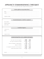
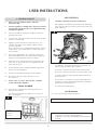
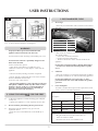
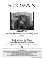
Riva Plus
Wood & Multi-fuel Free Standing Stove
Models:
SMALL, MIDI, MEDIUM & LARGE WOOD & MULTI-FUEL
Instructions for Use,
Installation and Servicing
For use in GB & IE (Great Britain and Republic of Ireland).
This appliance has been certified for use in countries other than those stated. To install this appliance in these countries, it is essential to obtain the translated
instructions and in some cases the appliance will require modification. Contact Stovax for further information.
IMPORTANT
This appliance will become hot whilst in operation, it is therefore recommended that a suitable guard should be used for the
protection of young children, the elderly or infirm. Do not attempt to burn rubbish in this appliance.
Please read these Instructions carefully before installation or use.
Keep them in a safe place for future reference and when servicing the fire.
The commissioning sheet found on page 3 of these instructions should be completed by the Installer.
PM231 - Issue 2 (November 2008)
COVERING THE FOLLOWING MODELs:
SMALL, MIDI, MEDIUM & LARGE WOOD & MULTI-FUEL
APPLIANCE COMMISSIONING CHECKLIST 3
COMMISSIONING
25
USER INSTRUCTIONS
MAINTENANCE & SERVICING
26
General Points
Using the Appliance for the first time
Recommended Fuels
Lighting the Fire
Running the Appliance
Burning Tips
Optional Fan Kit
Optional Outside Air Kit
Ash Removal
Extended Burning
Over-Firing
Chimney Fire General Cleaning
Cleaning Glass
Chimney Sweeping
Care of Stove
Seasonal Use
Troubleshooting Tips
4
4
5
5
6
6
8
9
9
9
9
9
9
10
10
10
10
11
11
Annual Service
Removal of Log Guard
Removal of Fire Brick
Removal of Baffle
Removal of Multi-fuel grate
Fitting a New Glass Door
Fitting a New Door Seal
Fitting & Removal of Multi-fuel grate
Fitting & Removal of Wood burning tray
Adjusting Door Hinges
BASIC SPARE PARTS LIST
29
SERVICE RECORDS
30
EC DECLARATION OF CONFORMITY
31
INSTALLATION INSTRUCTIONS
12
Technical Specifications
12
Standard Features
12
Packing List
12
Dimensions
13
SITE REQUIREMENTS
Flue & Chimney
Flue exit positions
Hearth Dimensions
Walls Next to Hearth
PRE-INSTALLATION
14
14
15
15
16
17
Flue
Additional Ventilation
Ventilation
17
17
18
INSTALLATION
19
Legal Requirements
Installing the Appliance
Top Flue Installation
Rear Flue Installation
Removal of Log Guard
Fitting & Removal of Baffles
Fitting & Removal of Fire Bricks
Fitting & Removal of Multi-fuel grate
Fitting & Removal of Wood burning tray
Optional Fan Kit
Optional Outside Air Kit
19
19
19
20
21
21
22
23
24
25
25
This appliance has been approved by HETAS Ltd.
2
26
27
27
27
27
27
27
27
27
28
APPLIANCE COMMISSIONING CHECKLIST
To assist us in any guarantee claim please complete the following information:-
Dealer appliance was purchased from
Name:..................................................................................................................................................................
Address:................................................................................................................................................................
. ...........................................................................................................................................................................
Telephone number:..............................................................................................................................................
Essential Information - MUST be completed
Date installed:......................................................................................................................................................
Model Description:...............................................................................................................................................
Serial number:......................................................................................................................................................
Installation Engineer
Company name:......................................................................................................................................................................
Address:..................................................................................................................................................................................
...............................................................................................................................................................................................
Telephone number:.................................................................................................................................................................
Commissioning Checks (to be completed and signed)
Is flue system correct for the appliance
YES
NO
Flue swept and soundness test complete
YES
NO
Smoke test completed on installed appliance
YES
NO
Spillage test completed
YES
NO
Use of appliance and operation of controls explained
YES
NO
Instruction book handed to customer
YES
NO
Signature:........................................................................................
3
Print name:................................................................
USER INSTRUCTIONS
AIR CONTROLS
1. General POINTS
1.1
1.2
Before use of this appliance please read these
instructions fully.
Only use for domestic heating in accordance with these
operating instructions.
1.4
You must burn only approved fuels. Do not use with liquid
fuels or as an incinerator.
1.5
Appliance surfaces become very hot when in use. Use
a suitable fireguard if young children, elderly or infirm
persons are present.
Stovax offer firescreens, sparkguards and hearthgate systems
for protection*. Your Stovax dealer can advise you about
these products.
1.6
1.7
1.8
1.9
Cleanburn Technology and Convector Efficiency
Riva appliances incorporate the latest cleanburn technology
with a unique 'Opti-Burn' setting in order to burn fuels with
greater efficiency.
All local regulations, including those referring to national
and European Standards need to be complied with when
installing the appliance.
1.3
5
4
1
Do not place photographs, TV’s, paintings, porcelain or
other combustible items on the wall or near the appliance.
Exposure to hot temperatures will cause damage.
3
1
Extractor fans or cooker hoods must not be placed in the
same room or space as this can cause appliance to emit
fumes into the room.
PR8021
Do not obstruct inside or outside ventilation required for
the safe use of this appliance.
1) Primary Air - burns the fuel under the fuel bed. For use
with solid fuel and initially with wood fires.
2) Airwash - air drawn over the window cleans the glass.
The source of Primary Combustion air when burning wood.
3) Unique 'Opti-Burn' setting provides optimum efficiency
and visual effect.
4) Clean burn - Secondary air is preheated through a heat
exchanger to combust unburned hydrocarbons, providing a
cleaner and more efficient burn.
5) Convected and radiant heat.
Do not make unauthorised changes to the appliance.
1.10 The chimney must be swept at least once a year.
See Section 13
1.11Do not connect, or share, the same flue or chimney
system with another appliance.
SERIAL NUMBER
1.12 This number is required when ordering spare parts or
making warranty claims.
2
DOOR HANDLE
The data is located under the appliance on a swing out
plate, See Diagram 1.
1.12 Use a protected gloved hand to operate.
DO NOT OPEN THE DOOR WITH BARE HANDS
PRODUCT:
MODEL No.
SERIAL No.
PR8020
4
*In the U.K: These products must conform to BS 6539,
Fireguards for use with solid fuel appliances.
If appliance is operating unattended they must conform to
BS 3248
USER INSTRUCTIONS
3. RECOMMENDED FUELS
Open
Open
3.1
Wood Logs:
• Burn only seasoned timber with a moisture content of less
than 20%
Close
Wood Length
Close
PR8023
PR8022
Appliance
1.16 To open and close the door, See diagram 3
WARNING
Properly installed, operated and maintained this
appliance will not emit fumes into the room.
Occasional fumes from de-ashing and refuelling may occur.
Persistent fume emission is potentially dangerous and
must not be tolerated.
If fume emission does persist:
• Open doors and windows to ventilate the room
•Allow fire to burn out or safely dispose of fuel from the
appliance
• Check for chimney blockage and clean if required
• Do not attempt to relight until the cause of the emission
has been identified and corrected
If necessary seek expert advice.
To allow the appliance to settle and fixing glues and paint
to fully cure:
• Operate the appliance at a low output for first few days
2.2
Do not touch the paint during the first period of use.
2.3
During this time the appliance may give off some
unpleasant odours:
• Keep the room well ventilated to avoid a build-up of fumes.
Riva Plus Midi
300mm
Riva Plus Medium
350mm
Riva Plus Large
400mm
• Dry newly cut wood for 12 to 18 months before use
Poor quality timber:
— Causes low combustion efficiency
— Produces harmful condensation
— Reduces effectiveness of the airwash and life of the
appliance
Do not burn construction timber, painted, impregnated
/ treated wood, manufactured board products or pallet
wood.
3.2
Solid fuel:
• Burn only anthracite or manufactured briquette smokeless
fuels listed as suitable for use with closed heating appliances
Do not burn bituminous coal, ‘petro-coke’ or other
petroleum based fuels as this will invalidate the product
guarantee.
3.3
Fuel consumption.
As tested at nominal heat output to the requirements of EN
13240: 2001 for intermittent operation:
Fuel Consumption
2. USING THE Appliance FOR THE FIRST
TIME
2.1
250mm
• All open flued appliances can be affected by temporary
atmospheric conditions which may allow fumes to enter
the house. Because of this it is recommended that an
electronic carbon monoxide detector conforming to
BSEN50291 be fitted and maintained.
Wood Length
Riva Plus Small
Description
5
Kg/hour
Wood
Kg/hour
Briquette
Smokeless fuel
Small Wood
RVP-SMW
1.48
-
Small M/F
RVP-SMM
-
0.75
Large Wood
RVP-LAW
3.30
-
Large M/F
RVP-LAM
-
1.78
*For Great Britain:
• Ring the Solid Fuel Association advice line on
0845 601 4406 for details
• Visit their web site at www.solidfuel.co.uk
USER INSTRUCTIONS
3.4 For advice on suitable solid fuels:*
• Contact your local approved coal merchant
A number of factors can affect the performance of the appliance.
See Section 16 for details.
Air Inlets
4. Lighting the fire
4.1
Log Guard
For best results:
• Set air controls, See Diagram 5
PR8028
• Close the door
Do not leave the door open as this could over-fire and
damage the appliance.
Wood
5. Running The appliance
Multi-fuel
Slide to the far right - resistance will be felt
PR8024
• Place firelighters or paper and dry kindling wood on the
grate
• Light the paper or firelighters, See Diagram 6
The Wood burning setting is:
Maxmium - Right
Minimum - Left
Once the fire is established:
• Move the control lever to the centre
A de-dent ball will locate the arm in the correct position see
Diagram 8.
This position is at maximum for burning wood.
The arm can be moved to the left to control the fire.
• Leave the door slightly open as the fire establishes and
the glass warms to avoid the build-up of condensation
• Add larger pieces of wood
Too many logs may smother the fire.
Do not load fuel above the log guard and the secondary
combustion inlets at the back of the firebox.
See Diagram 7
5.1 Wood Stove:
PR8025
6
Air Wash: Adjust
PR8032
• Wood burns best on a bed of ash
• Rake the embers evenly over the fire bed and open the
Airwash control fully for a few minutes before re-fuelling
5.2
Burn new logs at high output for a few minutes before
adjusting the Airwash control.
• Refuel little and often for clean, efficient burning.
USER INSTRUCTIONS
5.3
Experience establishes settings to suit personal preferences.
Opti Burn Position
Position 1: Full Running
Position 2: Opti-Burn
Adjust left to reduce output
PR8035
PR8032
• Minimum position for burning solid fuel, Diagram 11
• Lowest heat out put for burning wood (Opti Burn). This
position helps keep the glass clean, Diagram 9
PR8035
Shut Down Position
PR8027
• Lowest possible heat out put for burning wood. This
position does not keep the glass clean, Diagram 10
5.4
Do not burn large amounts of fuel with the Airwash control
closed for long periods of time. This reduces the glass
cleaning effect and causes tars and creosotes to build-up in
the appliance and flue system.
5.5
5.2
De-ash the fire bed before re-fuelling, See Ash Removal
• Open the Control fully to establish a glowing bed before
adding new fuel
• Burn new fuel at high output for a few minutes before
adjusting the Control to the desired setting
• Refuel little and often for clean, efficient burning.
When in use, burning the appliance at high output for a
short period each day also reduces tars and creosote.
• Maximum position for burning sold fuel. This position
helps keep the glass clean.
A de-dent ball will locate the arm in the correct position see
Diagram 12.
5.3
Experience establishes control settings to suit personal
preferences.
5.6 Multi-fuel Stove:
The Solid Fuel setting is from the Centre to the Left
The Wood burning setting is from the Centre to the Right
Once the fire becomes established:
• Move the control from the wood start up position, See
Diagram 6, to the Multi-fuel position on the left, Diagram
11
Full Heat Position
7
PR8036
USER INSTRUCTIONS
• This position gives full heat out put for burning solid fuel
but may discolour the glass, Diagram 13.
5.4
Do not burn large amounts of fuel with the Control on
low settings for long periods of time. This reduces the glass
cleaning effect of the airwash and causes tars and creosotes
to build-up in the appliance and flue system.
5.5
When in use, burning the appliance at high output for a
short period day also reduces tars and creosote.
5.6
You must burn only anthracite or smokeless fuels
suitable for use in closed appliances.
5.7
Do not burn bituminous coal, ‘petro-coke’ or other
petroleum based fuels as this invalidates the product
guarantee.
Do not load fuel above the log guard and the secondary
combustion inlets at the back of the firebox.
See Diagram 7
6.2
Air inlets puffing smoke
Combustion gases build up in the firebox and ignite as small
explosions, causing smoke to puff out of the air inlets and
other openings. This occurs if the air controls are shut soon
after adding new fuel to a very hot fire. Stop by opening the
air controls to increase combustion air and burning rate.
6.4
Flue Draught
The chimney has two main functions:
1) To safely remove the smoke, gases and fumes from the
house.
2) To provide a sufficient amount of draught (suction) in the
appliance ensuring the fire keeps burning.
Draught is caused by the rising hot air in the chimney when
the appliance is lit.
Symptoms of poor performance related to flue draught
include:
— Excessive fuel consumption (high flue draught)
— Poor burning control, overheating (high flue draught)
— Wind noise from air controls (high flue draught)
— Difficulty getting a fire going and keeping it burning well
(low flue draught)
— Low heat output (low flue draught)
— Smoke entering room when doors opened (low flue
draught)
6. Burning tips
6.1
6.3
Fuel Quality (Wood)
Use wood with a moisture content of less than 20%.
Seasoned logs have the bark beginning to lift and peel away
and cracks radiating from the centre. They feel lighter than
fresh cut wood of a similar size and sound hollow when
struck against each other. Logs should not feel damp or
have moss and fungal growths.
Symptoms related to wet wood:
— Difficulty starting and keeping a fire burning well
— Smoke and small flames
— Dirty glass and/or firebricks
— Rapid creosote build-up in the chimney
— Low heat output
— Short burn times, excessive fuel consumption and
blue/grey smoke from the chimney
• Burn at high output for a short period each day to avoid
large build-ups of tars and creosote within the appliance
and the flue system
• Use Stovax Protector chimney cleaner to reduce this
problem
Fuel Quality (Solid Fuel)
• Use recommended solid fuels approved for use with
closed appliances.
Symptoms related to unsuitable fuels include:
— Difficulty starting and keeping a fire burning well
— Smoke and small flames
— Dirty glass and/or firebricks
— Short life span for grate, baffles and internal firebricks
— Permanent staining of glass
8
The construction, position, size and height of the chimney
all affect the performance of the flue draught.
Other factors effecting the flue draught include:
— Trees or other buildings nearby causing turbulence
— High and gusty winds
— Outside temperature
— Outside weather conditions
— Incorrect additional ventilation to building
— Blocked flue / chimney
For advice on the correction of persistent flue problems
consult a qualified solid fuel heating engineer before
continuing to use the appliance.
6.5
Weather conditions
The weather conditions outside the building can effect the
burning performance of the appliance. These could include:
Weather Conditions
Problem
Effect
Windy days
Buildings/Obstacles
cause turbulent air
around chimney.
Smoky Appliance
Calm days
Oversized Chimney.
Smoky Appliance
Damp / Rainy days
Flue temperature
not hot enough.
Rain water inside
chimney.
Lighting and
burning problems
USER INSTRUCTIONS
To reduce these problems:
• Use good quality kindling wood to start the fire
• Burn initially at a high temperature for a short period
• Fit a rain cowl to the chimney
Your installer should advise you on possible solutions.
If the appliance emits smoke into the room continuously:
• Close the air controls and allow the appliance to go out
• Ventilate the room to clear the fumes
Do not re-light the appliance until the problem is solved.
PR8030
7. Fan kit
7.1
This appliance can be fitted with an optional convection fan
kit. For installation and operating procedures you must refer
to the instructions supplied with the fan kit.
8. Outside air kit
7.1
This appliance can be fitted with an optional kit to help
bring air directly into the appliance from outside. For
installation and operating procedures you must refer to the
instructions supplied with the kit.
10. Extended burning
10.1 It is possible to get the appliance to burn for extended
periods of time.
In order to do this:
• De-ash prior to final refuelling
9. ASH REMOVAL
9.1
All fuels:
To riddle the appliance:
• Insert the Riddling tool into the socket as shown in
Diagram 14
• Use gloves, or place the ash into a Stovax Ash Caddy
(Stovax Part No. 4227)
• Remove ash at least once every week when burning
wood
• Do not place hot ash in a bin made from plastic or any
other combustible material.
• Set air controls to low combustion settings
This will blacken the glass but it will clear when operated at
high output for a short period.
• Use smokeless fuel or small, thick logs depending on fuel
desired
11. OVER-FIRING
11.1 Do not over-fill with fuel or use at maximum output for
long periods or over-firing can occur. If the flue pipe, flue
collar or top plate glow red the appliance is over-firing:
• Close the air controls to reduce the output
11.2 Over-firing can cause permanent damage to the appliance.
PR8031
12. Chimney fire
• Move the Riddling tool vigorously backwards and
forwards
The ash falls into the ashpan
9.2
• Open the doors
• Remove Ashpan carefully using tool supplied
Heat can remain long after use.
12.1 If a chimney fire occurs:
9
• Shut all air controls immediately
• Evacuate the building
• Call the fire brigade
• Do not re-enter the building until it is confirmed safe
USER INSTRUCTIONS
15. CHIMNEY SWEEPING
12.2 Do not use the appliance after a chimney fire until:
a) It has been inspected by a registered installer,
confirming the appliance is safe to use*
15.1 To maintain safe and efficient use of the appliance the
chimney/flue must be inspected and swept at least once a
year by a qualified chimney sweep.*
b) The chimney system inspected and swept by a chimney
sweep, confirming the system is structurally sound and free
from obstruction before re-use.**
c) It is repaired as required before re-use. Use only
genuine Stovax replacement parts to keep your appliance in
safe and efficient working order.
If the appliance is used continuously throughout the year
or it is used to burn wood or smokeless fuel, more frequent
sweeping is recommended.
The best time to have the chimney swept is at the start of
the heating season.
The above applies even if burning smokeless fuels.
13. GENERAL CLEANING
13.1 Allow appliance to cool thoroughly to avoid risk of burns:
• Clean regularly, according to the level of use
• Give attention to the baffle system, flue ways and
removing ash
Regular cleaning and maintenance will help give many years
of safe use.
• Clean matt black appliances using Stovax Collodial black
or Stovax Grate Polish
To refresh painted finishes use Stovax Thermolac paint.
• Clean enamel finishes using warm soapy water and a soft
clean cloth
• Do not use aerosol sprays near an operating appliance
15.2 The chimney, any connecting flue pipe and the appliance
flue ways if incorporated, must be regularly cleaned.
15.3 Ensure adequate access to cleaning doors where it is not
possible to sweep through the chimney.
15.4 If the appliance is believe to have previously served an
open fire the chimney must be swept a second time within
a month of regular use after installation.
16. Care of stove
Wipe dry with a soft clean cloth before re-lighting. Do not
leave unit without drying, as this may cause rust.
Do not use abrasive cleaner or cleaning pads to clean
enamel finishes.
Stovax has a range of cleaning and maintenance products and
accessories to keep your appliance in good working condition.
Your Stovax retailer can provide full details but here is a brief list of
useful items:
14. CLEANING GLASS
Product Code
Description
3047
Extra long matches
• Keep the glass clean with correct use of the Airwash system
and good quality fuel
Sometimes additional cleaning may be required.
5039
Gas lighter
4052
Log basket
14.1
This can be done as follows:
• Allow appliance to cool fully
Do not clean hot glass.
• Use a soft cloth and Stovax Glass Cleaner
3048
Wood sling - for easy carrying of logs
3016
Log tongs
4027
Extra long protective gloves
5038
Hearthgate - 5 section (for areas 1780x610mm
5044
Hearthgate - 7 section (for areas 1780x405mm)
4227
Ash caddy - 382x102x306mm
4228
Ash caddy - 446x102x306mm
4229
Ash caddy - 382x102x459mm
4230
Ash caddy - 637x127x408mm
4231
Ash caddy - 306x178x459mm
2091
Ashclean vacuum cleaner attachment
4232
Steel brush
14.2 Before re-lighting the appliance:
• Dry the glass fully
14.3 Do not use abrasive cleaner or cleaning pads.
In the U.K:
* registered with HETAS (GB only)/INFO (Republic of
Ireland only)
**This should be done by a NACS registered (UK only)/
INFO registered (Eire only) chimney sweep, who will issue
you with a certificate.
10
USER INSTRUCTIONS
18.4 Appliance is producing tar:
This is identified by:
• A very strong pungent smell shortly after the appliance is
lit and heats up
• Glass blackening
• Thick, brown and sticky tar oozes from the pipe joints
Your retailer can provide genuine spare parts such as replacement
glass, door sealing rope and fire bricks when required. An annual
service by a competent engineer is recommended to keep your
appliance in best possible condition.
17. Seasonal use
17.1 Clean and service the appliance if it is not used during the
warmer periods of the year as detailed in the Maintenance
and Servicing section
17.2 Set the air controls 50% open to keep the appliance
ventilated and stop the build-up of any moisture inside.
17.3
Before re-lighting the appliance:
• Remove the baffles
• Clear any debris that may have accumulated
• Check the flue is clear of any blockages
18. Troubleshooting tips
18.1Stove glass blackening:
This has four possible causes:
1.
Incorrect use of airwash – See Sections 1, 4 and 5 for the
correct use of the air controls.
2.
Burning unseasoned wood – See Section 3 to identify
when wood is ready for burning.
3.
Stove operated at too low a temperature - good working
temperature is 300-500° F (120 – 250° C). A stove pipe
thermometer can identify this problem (Stovax part no
3046)
• Burn with the airwash control fully open for
approximately 20 minutes to cure this
The problem may be caused by damping your appliance
down overnight.
4.
Problems with the flue – in particular insufficient air pull. If the flue is not working efficiently the glass can blacken.
A flue which has too much downdraft may be too short or
needs lining or has too many bends. This can also cause
blackening of your stove glass. Contact the installer or a flue
specialist for advice.
18.2 Riddling mechanism jamming:
This occurs when fine ash builds up under the riddling bars
preventing movement. To prevent this:
• Follow a regular cleaning routine for the inside of your
appliance
• Lift out the riddling mechanism and remove all ash
• Replace riddling mechanism when cleaning is complete
18.3 Glass cracking:
Do not over tighten the screws on the glass clips when
replacing the glass as this causes stress and the intense
temperature changes can cause the glass to crack. For
replacement glass contact your local Stovax dealer.
11
This is caused by burning damp wood and burning your
appliance at too low a temperature;
• Use well seasoned wood and operate the appliance in the
ideal temperature range
Tar is a major cause of chimney fires - if you experience
problems with tar build up consult a chimney sweep before
continued use of your appliance.
Ideal working temperature range is 130°C and 240°C
(270°F – 465°F). Failing to close down the primary air
control once the appliance has heated up to this range
may cause the appliance to over-fire and to exceed the
ideal temperature range. Over-firing can cause permanent
damage to the appliance and invalidates your warranty.
TECHNICAL SPECIFICATION
Riva Plus Small
RVP-SMM/RVP-SMW
MODEL:
Riva Plus Small RVP-SMM/RVP-SMW
Riva Plus Large RVP-LAM/RVP-LAW
Nominal Heat Output
Wood
kW
5.0
11.0
Solid Fuel
kW
5.0
11.0
mm Wg
1.5
1.5
inch Wg
0.05
0.05
Pa
12.5
12.5
Wood
g/s
4.5
7.9
Solid Fuel
g/s
4.4
6.0
Wood
C
290
326
Solid Fuel
C
251
408
mm
128
153
inch
5
6
Kg
95
175
Flue Draught at Nominal Heat Output
Flue Gas Mass Flow
Flue Gas Temperature at Spigot / Socket
All
Flue Outlet Six (Top/Rear Option)
Weight
Recommended Fuels
Wood
Solid Fuel
Seasoned wood (less than 20% moisture content)
Briquette smokeless fuel suitable for closed appliances
(Ancit-Phuracite-Taybrite-Homefire Ovals)
As tested to the requirements of EN 13240 for intermittent operation
1. STANDARD FEATURES
•
•
•
•
•
Riva Plus Large
RVP-LAM/RVP-LAW
RIVA APPLIANCE
2. PACKING LIST
•
•
•
•
•
•
•
•
•
•
•
Primary air
Airwash
Secondary air control (to ensure complete burning of flue
gases)
Riddling grate system for clean de-ashing – (Multi-fuel
appliances only)
Top or rear flue exit option
12
Instructions
Guarantee card
Flue Collar
Tools: Hex Keys
Gloves
Blanking Plate
Door Tool - Double Door Only
Ash Pan Tool - Multi-fuel
Accessories Catalogue
Thermic Seal
Riddling Tool - Multi-fuel
SITE REQUIREMENTS
RIVA DIMENSIONS
J
G
D
Riva Small
E
H
A
B
C
I
PR8119
F
K
D
G
J
E
Riva Large
H
A B C
I
F
K
PR8120
Description
Model
A
B
C
D
E
F (dia)
G
H
I
J
K
Riva Plus Small
RVP-SMM/
RVP-SMW
723
637
551
474
420
105
338
128
438
128
378
Riva Plus
Large
RVP-LAM/
RVP-LAW
1013
848
687
700
640
166
463
150
549
153
499
All dimensions in mm. (25.4 mm = 1”)
13
SITE REQUIREMENTS
1. FLUE OR CHIMNEY
1.5
You must sweep and inspect the flue when the appliance is
installed.
1.6
You must check the flue draught with all windows and
doors closed and any extraction fans in this or adjoining
rooms running at maximum speed. (See next section for
additional ventilation requirements)
Max. Draught = 2.0mm Wg
Min. Draught = 1.0mm Wg
In the U.K:
*BS 6461: Part 1, and the requirements of Building
Regulations
— Enure the connecting flue pipe it kept a suitable
distance from any combustible material and does not form
part of the supporting structure of the building
**This should be done by a NACS registered (UK only)/
INFO registered (Eire only) chimney sweep, who will issue
you with a certificate.
† Building Regulations Document J
— Make provision to remove the appliance without the
need to dismantle the chimney
— Any existing flue must be confirmed as suitable for the
new intended use as defined in the Building Regulations
— The flue or chimney systems must be inspected and
swept to confirm the system is structurally sound and free
from obstructions**
Flue Plate:
Where a hearth, fireplace, flue or chimney is provided or
extended (including cases where a flue is provided as part of refurbishment work), information essential to the
correct appliance and use of these should be permanently
posted in the building, to meet Requirement J4 of the
Building Regulations (England and Wales), F3.12 (Scotland).
† Building Regulations Document J
1.1
The flue or chimney system must be in good condition.
It must be inspected by a competent person and passed for
use with the appliance before installation
Products of combustion entering the room can cause
serious health risks.
1.2
You must check the following:
— The construction of the masonry chimneys, flue block
chimneys and connecting flue pipe system must meet the
requirements of the Building Regulations†
— A flexible flue liner system can be used if certified for
use with solid fuel systems and installation complies with
manufacturer’s instructions and Building Regulations.
The flue liner must be replaced when an appliance is
replaced unless proven to be recently installed and in good
condition.
— If it is necessary to fit a register plate it must conform to
the Building Regulations†
— The minimum height of the flue or chimney must
be 4.5m from the hearth to the top of the flue, with no
horizontal sections, a maximum of 4 bends with angles of
less than 45 degrees
— If the appliance is believe to have previously served an
open fire the chimney must be swept a second time within
a month of regular use after installation to clear any soots
falls that may occurred due to difference in combustion
levels.
— The flue exit from the building must comply with local
building control rules.†
— Do not connect or share the flue or chimney system
with another heating appliance
1.3
Do not connect to systems containing large voids or over
230mm square.
1.4
You must provide suitable access to enable the collection
and removal of debris.
14
Additional:
A new factory made system that complies to EN 1856; Part 1
can be used providing installation is to the requirements of:
i) BS 7566 Parts 1 -4
ii) the manufacturer's instructions
iii) Building Regulations.
For a guide containing information on Chimneys and Flues contact: The British Flue & Chimney Manufacturers’ Association,
FETA
2 Waltham Court
Milley Lane
Hare Hatch
Reading
Berkshire RG10 9TH
Tel: 0118 9403416
e-mail: [email protected]
SITE REQUIREMENTS
1. FLUE OUTLET POSITIONS
Terminal
Flue
Vertical
Measurement
Horizontal
Measurement
150mm
max
Insulation
Adjacent
Building
The vertical measurement is the lowest from either the
point of discharge or 150mm above insulation.
Position On Roof
Minimum Clearances
A
On ridge or within 600mm
600mm above ridge
B
Elsewhere on roof
2300mm horizontally from roof surface and:
a) 1000mm above highest point of flue exit
from roof or
b) as high as the ridge
C
On pitched, within 2300mm horizontally to
openable window, dormer
1000mm above top of opening
D
Within 2300mm of another building
600mm above top of building
IMPORTANT: Seek specialist
advice if installing in a dwelling
with a thatched roof
2. HEARTH DIMENSIONS
150mm
minimum
150mm
minimum
Constructional 225mm
Hearth 840mm minimum
minimum
The appliance must stand on a constructional hearth with
the minimum dimensions as shown in the diagram below.
2.2
The building must have a suitable load-bearing capacity for
the hearth and appliance.
• Consult a structural engineer for advice before
proceeding
150mm
minimum
Change in level to
mark safe perimeter
2.1
Constructional
Hearth 840mm
minimum
PR8077
15
2.3
When fitting into an existing hearth check:
• that the appliance complies with current construction
regulations and is at least the minimum sizes shown
2.4
If there is no existing fireplace or chimney it is possible to
construct a suitable non-combustible housing and hearth
setting. The flue must be installed in accordance with all
local and national regulations and current rules in force .
• Check if adding a new chimney to your property requires
planning permission
SITE REQUIREMENTS
3. WALLS NEXT TO A HEARTH
Thickness W
Solid, non-combustible
material e.g. masonry
or concrete
Stove
H
Wall Thickness 'W'
C
150mm
minimum
C
150mm
minimum
Position of Appliance & Hearth in relation to walls
PR8051
Requirement for the walls
Distance of hearth from wall
'C'
Distance of Appliance to wall
Min thickness of Wall
'W'
Min height of wall
'H'
0mm
0mm - 50mm
200mm
0mm
51mm - 300mm
75mm
Height of appliance + 300mm
Or
1200mm from the hearth (take largest
dimension)
0 - 150mm
150mm +
75mm
1200mm
150mm +
300mm +
No Minimum Requirement
Suitable clearance should be allowed around the stove to enable the correct fitting and maintenance of the appliance.
Any clearances should be confirmed by making a site survey and a physical check of wall thickness and dimensions.
16
PRE-INSTALLATION CHECKS
1. Flue
Riva Traditional Small
RVP-SMM/RVP-SMW
Riva Traditional Large
RVP-LAM/RVP-LAW
MODEL:
Riva Plus Small RVP-SMM/RVP-SMW
mm
150
150
inch
6
6
mm
135
135
inch
51/2
51/2
With liner or Factory made system
(diameter)
mm
†150
†150
installed in accordance with manufacturer's instructions
inch
†6
†6
metre
4.5
4.5
feet
13
13
Riva Plus Large RVP-LAM/RVP-LAW
Without flue liner Round (diameter)
Flue/Chimney Size
Flue/Chimney
Without flue liner system Square
(diameter)
All products
(*minimum height)
* When measured from the top of the stove to the top of the flue, with no
horizontal sections and a maximum of 4 bends with angles of less than 45o
†May be 125mm (5") if only burning low volatiles (smokeless) fuels approved for use in Smoke Control Areas.
See website http://uksmokecontrolareas.co.uk for more information about approved fueld
2. ADDITIONAL VENTILATION
2.2
Extractor fans or cooker hoods must not be placed in the
same room or space as this can cause the appliance to emit
fumes into the room.
2.3
If any of these checks reveal problems do not proceed
with the fitting of the appliance until they have been
rectified.
MODEL:
Riva Plus Small RVP-SMM/RVP-SMW
Riva Plus Large RVP-LAM/RVP-LAW
Additional Ventilation
17
Riva Traditional Large
RVP-LAM/RVP-LAW
Additional ventilation is required to comply with the
requirements of the Building Regulations. This must be
provided using a permanently open air vent, of the size
listed, which is positioned so that it is not liable to be
blocked both inside and outside the building.
Riva Traditional Small
RVP-SMM/RVP-SMW
2.1
mm2
NONE
3300
cm2
NONE
33.0
in2
NONE
5.12
PRE-INSTALLATION CHECKS
3. ventilation
3.1
This appliance requires ventilation to supply combustion air.
Any room containing the appliance must have a permanent
air vent opening with a total free area of at least 550mm2
per kW of appliance rated output above 5kW.
3.2
Increase air supply provisions where a room contains
multiple appliances.
3.3
If vents open into adjoining rooms or spaces there must be
an air vent of at least the same size direct to the outside.
3.4
Permanent air vents should be non-adjustable and
positioned where they are unlikely to become blocked.
3.5
Site the vents where cold draught is unlikely to cause
discomfort. This can be avoided by placing vents near
ceilings or close to the appliance, see Diagram opposite.
3.6
This appliance can be fitted with an optional kit to help
bring air directly into the appliance from outside. For
installation and operating procedures you must refer to the
instructions supplied with the kit.
18
INSTALLATION INSTRUCTIONS
Legal requirements
Before installation of this product please read these
instructions fully.
It is very important to understand the requirements of the national
Building Regulations* and standards**, along with any local
regulations and working practices that may apply. Should any
conflict occur between these instructions and these regulations
then the regulations must apply.
1.1
Take care when installing the appliance. Careless
handling and use of tools can damage the finish and/or
area.
1.2
• Select and fit the required flue option
The appliance is factory supplied with a top flue outlet but
the flue collar and blanking plate require sealing with Fire
Cement before use, Diagram 1
Decorative
Ring
Your local Building Control Office can advise regarding the
requirements of the regulations.
The appliance must be fitted by a registered installer†, or
approved by your local building control officer.
Works must be carried out with care to meet the requirements of
Health and Safety‡ and comply with the Health and Safety rules,
and any new regulations introduced during the lifetime of these
instructions.. Particular attention should be drawn to:
• Handling: The appliance is heavy. Adequate facilities
must be available for loading, unloading and site handling.
• Fire Cement: Some fire cement is caustic and must not
come into contact with the skin. Protective gloves must be
worn. Wash hands thoroughly with plenty of water after
contact with skin.
• Asbestos: This appliance contains no asbestos. If there
is the possibility of disturbing any asbestos in the course of
installation seek specialist guidance and use appropriate
equipment.
• Metal Parts: Take care when installing or servicing the
stove to avoid personal injury.
Fire Cement
PR8063
2. TOP FLUE INSTALLATION
A faulty installation can cause danger to the inhabitants and
structure of the building.
For users of this appliance:
Your building insurance company may require you to inform them
that you have installed a new heating appliance. Check that your
cover is still valid after installing the appliance.
2.1
To fit the pipe to the collar:
• Lift appliance into position
• Take care not to damage the hearth finish
• Connect appliance to the chimney using flue pipe
• Secure with self tapping screw
• Seal the connecting joints
1. INSTALLING THE Appliance
Each installation is unique to the property so it is not possible
to give details to suit every setting. The installation must comply
with Building Regulations and be made using "best practice"
construction methods.
Many fireplace openings have a supporting lintel. Do not remove
without supporting the remaining structure of the building. Do not
support the structure with the appliance or the flue system.
PR8149
In The U.k:
* England and Wales – Document J / Scotland - Part F/
Document J (Republic of Ireland only)
** In the U.K BS 8303, BS 6461, BS 7566
† registered body: HETAS (GB only)/INFO (Eire)
‡ Health and Safety at Work Act 1974
19
The Flue must be installed in accordance with
manufacturers instructions.
INSTALLATION INSTRUCTIONS
3. REAR FLUE INSTALLATION
Flue pipe x 612 long
Because the stove is supplied for top flue exit, you need to
move the blanking plate to the top of the appliance and the
fit the collar and flue pipe to the rear:
3.1
(Tools required - cross-headed screw driver, 10mm A/F
spanner/socket wrench and a key hole saw).
• Remove the flue break-out cover using a small key hole
saw to cut the 3 securing lugs
Self tapping screws
Seal Collar with
fire cement
PR8054
All models
2.2
Connect a flue pipe 612mm long by inserting it into the flue
spigot and seal using fire cement. Fit the cast iron finishing
collar over the flue pipe and locate into recess in the top
cover
3 Small Lugs
Cut Using
Saw
Connection to chimney as detailed
in Building Regulations
PR8064
1000mm max
unsupported
600mm minimum
135 Elbow with
access cover
3.2
To change from top to rear exit flue, reverse the flue spigot
and blanking plate using the method detailed.
• Remove the upper and lower baffle, see Section XX
Flue Pipe x 612 long
Flue collar
Upper &
Lower Baffle
Rear bricks
Blanking
cover
PR8065
All Models
PR8052
20
• Remove the top bricks, see Section 5
• Remove the flue collar using a 10mm A/F spanner/socket wrench to remove the 4 fixing bolts including the 2 flanged
spacers
• Remove the blanking plate using a 10mm A/F spanner/socket wrench to take out the 4 bolts
INSTALLATION INSTRUCTIONS
3.3
3.5
Fitting the flue collar and blanking plate to the top
Typical Top Flue Pipe Installation
Connection to chimney
as detailed in Building
Regulations
Flue Collar
Fire Cement
Flanged Collar
3.4
135 Elbow with access cover
1000mm max
unsupported
600mm
minimum
600mm
minimum
Blanking Cover
Flue pipe x 612 long
PR8066
4. REMOVAL OF THE LOG GUARD
The following flue pipe is available to ensure safe
installation:
5" Tee
Stovax Product Code 4516
6" Tee
Stovax Product Code 4616
5" 135o Bend
Stovax Product Code 4512
6" 135o Bend
Stovax Product Code 4512
5" Flue Pipe x 612mm long
Stovax Product Code 4501
6" Flue Pipe x 612mm Long
Stovax Product Code 4601
PR8053
All models
• Fit the blanking plate to the top flue outlet
• Use the 4 bolts (including the 2 flanged spacers as
shown), seal to the firebox as shown using fire cement
• Fit the flue collar to the rear flue outlet using the 4 bolts
from the cover plate
• Seal to the firebox using fire cement
• Do not replace the top, rear or centre firebricks
• Re-install upper and rear baffle
4.1
To remove the Log guard:
• Lift Log Guard clear of the supporting brackets
• Rotate to clear the sides of the door opening.
Do not use appliance without the log guard in position.
Self-tapping screw
PR8114
5. FITTING AND REMOVAL OF
THE BAFFLES
Tee with cap
No tools are required.
5.1
To maintain efficient combustion the Riva Stove is fitted
with a twin baffle system, consisting of upper and lower
baffles.
5.2
First remove the Log Guard from the stove to give access to
the firebox.
Cap
Seal collar with fire cement
All models
PR8055
21
INSTALLATION INSTRUCTIONS
6. FITTING AND REMOVAL OF
THE FIRE BRICKS
Upper Baffle
Lower Baffle
6.1
Remove the firebricks as part of the routine maintenance.
This can be carried out without the use of tools.
6.2
Allow the appliance to cool fully before removing firebricks.
6.3
Take care when handling, as bricks can become fragile after
use. Life span depends on the type of fuels burnt and the
level of use.
6.4
PR8057
5.3
• Replace damaged bricks as soon as possible
Remove the Lower Baffle (see diagram) by lifting the front
edge to unhook it from the support bars
• Pull the baffle forward to disengage the rear edge from
the location above air inlet holes
• Rotate the baffle to remove from the firebox through the
door opening.
Remove the baffles and grate system
• Remove secondary air facia plate screws using a
pozidrive screwdriver
• Remove the bricks in the correct order as shown in
Diagrams 11 and 12
Riva PLUS Small
6
8
7
4
5
3
2
Lower Baffle
PR8058
1
5.4
5.5
Next, remove the Upper Baffle (see diagram) by pulling
forward to disengage it from the hanging points at the top
of the firebox
• Rotate the baffle to remove it from the firebox through
the door opening.
Reverse the above process to replace the baffles
PR8118
Riva PLUS Large
8
7
9
5
6
4
3
1
2
Upper Baffle
PR8059
Do not modify the baffle
22
PR8061
INSTALLATION INSTRUCTIONS
7. FITTING AND REMOVAL OF
THE Multi-fuel grate
7.1
The Multi-fuel grate can be removed for cleaning to
maintain good working condition.
To remove the grate:
• Remove the log guard to enable access, See Section 4
• Remove the ashpan
• Remove the Riddling Bars, Diagram 16
5mm
Hex Key
Riddling
Boss
Fixing
Bolt
PR8111
• Remove Riddling Cam Bar, Diagram 19
Lift bars to
remove
PR8109
• Remove Rear Bar, Diagram 17
PR8112
To remove Multi-fuel frames:
• Remove bricks, see Section 3
• Lift frames from the front
• Remove Right Hand Side first through the front of the
stove
• Repeat for the Left Hand Side
PR8110
To remove the Riddling Boss:
• Use the 5mm Hex Key as shown in Diagram 18
• Unscrew the Boss
PR8113
23
• Replace in reverse order
INSTALLATION INSTRUCTIONS
8. FITTING AND REMOVAL OF
THE wood burning tray
8.1
The Wood Burning tray can be removed for cleaning to
maintain good working condition.
To remove the Wood tray:
• Remove the Log guard, see Section 4
• Remove the bricks, see Section 5
• Remove Right Hand Side first through the front of the
stove
• Repeat for the Left Hand Side
PR8115
• Replace in reverse order
9. Fan kit
9.1
This appliance can be fitted with an optional convection fan
kit. For installation and operating procedures you must refer
to the instructions supplied with the fan kit.
10. Outside air kit
10.1 This appliance can be fitted with an optional kit to help
bring air directly into the appliance from outside. For
installation and operating procedures you must refer to the
instructions supplied with the kit.
24
COMMISSIONING
COMMISSIONING
1.1
To commission:
• Replace the firebricks, baffle, and log retainer
• Check the door alignment and catch operation, adjust if
required, see Installation Section 6. Adjusting Door hinges
• Check the soundness of door seals, castings and joints
• Check the operation of the air controls
1.2
Now carry out a final smoke draw test:
PRODUCT:
MODEL No.
SERIAL No.
• First warming the flue with a blowlamp, or similar, for
about 10 minutes
PR8020
• Place a smoke pellet on the centre of the grate, with the
air controls open
• Record dealer/supplier details and installer details in
Instructions
• Close the door
Smoke should now be drawn up the flue and be seen to
exit from the flue terminal
• Record serial number in page 3 of Instructions
This number is required when ordering spare parts and
making warranty claims
• Complete test with all doors and windows closed in the
room where the appliance is fitted
• Give the copy of the Instructions to the customer
• If there are any extractor fans in adjacent rooms, the test must be repeated with the fans running on maximum and
interconnecting doors open
• Check the effect of ceiling fans during the test
If the test fails, re-check the suitability of the flue system
and ventilation. An inadequate air supply to the room is
potentially dangerous.
• Light the appliance and slowly increase the temperature
to operating levels
• Explain the cleaning and routine maintenance
requirements
• Ensure no combustion products enter the room
• Open the main fire door when the appliance reaches
operating condition and carry out a spillage test with a
smoke match or pellet around the door opening
1.3
If excessive spillage occurs:
• Allow the appliance to cool and re-check the flue system
and ventilation
1.7
Finally:
• All open flued appliances can be affected by temporary
atmospheric conditions which may allow fumes to enter
the house. Because of this it is recommended that an
electronic carbon monoxide detector conforming to
BSEN50291 be fitted and maintained.
• Explain the safe operation of the appliance and the use
of the controls to the user and the importance of only
using suitable fuels
25
MAINTENANCE and SERVICING
For a complete list of spare parts and accessories contact your Stovax or call 01392 474011
1. ANNUAL SERVICE
1.1
At the end of the heating season strip, inspect and clean the
appliance as detailed:
• Allow appliance to cool
• Remove all of the following internal parts; baffle,
firebricks, complete grate, and ash pan. For Multi-fuel
versions remove the complete grate and ash pan.
See sections 3 and 4 on how to remove the baffles and
firebricks. Take care handling firebricks, as they can become
fragile after a period of use.
• Lightly oil the door catch mechanism and hinge pins
Avoid getting oil onto the door seals and glass.
To refresh painted finishes use Stovax Thermolac paint.
1.2
Use genuine Stovax replacement parts to keep your
appliance in safe and efficient working order. Your local
Stovax dealer can provide you with the parts you require. This is a list of the maintenance products you may need to use
Task
• Vacuum clean any remaining ash and debris from the
inside of the appliance.
Stovax offer a filter/collection attachment for your vacuum
cleaner to protect it from fire ash. Ash Clean (Stovax Part
No. 2091).
4111
Stove glass cleaner
(spray on)
4103
Protector (15 sachets)
7002
Protector (1kg tub)
7025
Fire Cement (500g tub)
2020
Fire Cement (600g cartridge)
2021
Thermolac Black
(400ml aerosol)
2019
Thermolac Black
(200ml brush-on)
2057
Cleaning matt
black Appliances
Colloidal black (85ml)
7000
Protecting your
hands
Heat resistant leather gloves
4008
14mm Black rope seal
(handy pack)
5000
14mm Black rope seal
(25m reel)
4670
3mm Black rope seal
(handy pack)
4975
3mm Black rope seal
(25m reel)
4974
Preventing buildup of creosote in
flue
Sealing flue pipe
joints
• Clean the grate parts with a wire brush, and check the
parts for any damage
• Replace any damaged parts
• Check and clean the firebricks with a soft brush
• Replace broken bricks
Some surface damage will occur during use. The life of
the bricks will depend on the type of fuels burnt and the
level of use. Damaged bricks should be replaced as soon as
possible.
• Re-fit cleaned internal parts
• Remove the glass from the door and discard all old rope
seals
• Remove the door rope seal from the outer edge of the
door and clean the old glue from the door sealing rope
groove
• Clean the door glass using Stovax Glass cleaner and a soft
cloth
Do not use abrasive cleaners to remove tar or soot deposits
from the glass.
Re-painting
Door sealing rope
Glass sealing tape
Thermic seal glue (50ml bottle)
10mm diameter
4965
Ash Clean
Vacuum Cleaner Attachment
2091
• Replace the glass edge seal with new and re-fit the glass
into place in the door
• Fit new door rope seal, gluing it in place with Stovax
Thermic Seal rope adhesive
• Press the new door sealing rope into the locating groove,
placing the joint in the middle of the lower edge of the
door.
When fitting new door seals, close the appliance door and
leave for at least 12 hours before using. This allows the
adhesive to fully bond to the seal before use.
1.3
26
5037
Soft rope
Stovax Code
Number
Stove glass cleaner 500ml
(wipe on)
Glass cleaning
• Clean the internal surfaces of the appliance using a wire
brush and scraper as required
Vacuum and brush the resulting debris from the appliance.
Product name
These products, available from your local Stovax dealer,
along with regular maintenance and use of correct fuels, will
keep your appliance in the best possible condition.
If you require more information about Stovax group
products visit our web site www.stovax.com
MAINTENANCE and SERVICING
7.1
To maintain the safe use of your stove you may need to
replace a damaged door glass. To complete this operation:
• Lift the door free of the hinge blocks on the right of the
single door or both side for the double door
• Lie the door on a soft flat surface, to protect the glass and
the paintwork
• Use a 2.5mm A/F hexagon key to remove the exposed
fixing screws in the glass clamp, see Diagram
The old glass can then be lifted clear of the door. (Note
how the edge sealing tape is fixed.) Remember to dispose
of the old glass safely.
• Clean, and re-paint, the rear of the door if required
• Clean the screws with light oil or WD40® to aid future
removal
• Fit the edge sealing tape to the new glass
See Section 6, Installation Instructions, to remove and
replace the baffles.
• Place the glass into position in the door
5. REMOVAL OF MULTI-FUEL GRATE
• Place the door glass clamp back in to position and re-fix
with the clean fixing screws
7.2
Fit only Stovax Ceramic Glass, which is suitable to use in
high temperature applications.
7.3
Using the appliance with a damaged door glass could cause
dangerous fumes to enter the room, or the stove to over
fire, resulting in damage.
1.4
Using the appliance for the first time:
• Burn at a low output for the first day of use
This allows the seals, fixing glues and paint to fully cure.
1.5
During this time the appliance may give off some
unpleasant odours:
• Keep the room well ventilated to avoid a build-up of
fumes.
1.6
Your Stovax dealer can carry out service and maintenance.
2. REMOVAL OF THE LOG GUARD
2.1
See Section 4, Installation Instructions, to remove and
replace the log guard:
3. REMOVAL OF FIRE BRICKS
3.1
See Section 5, Installation Instructions, to remove and
replace fire bricks
4. FITTING AND REMOVAL OF BAFFLE
4.1
5.1
See Section 5, Installation Instructions, to remove and
replace the multi-fuel grate.
6. REMOVAL OF WOOD BURNING TRAY
6.1
See Section 7, Installation Instructions, to remove and
replace the wood burning tray.
8. Fitting a new door seal
ALL MODELS
7. FITTING A NEW DOOR GLASS
ALL MODELS
8.1
Door Rope Seal
Fixing Screw
Glass Clamp
Glass
Glass Edge Seal Tape
Door Cross
• Lay the door face down on a soft flat surface, to protect
the paintwork and glass
• Remove the old rope and scrape old glue from the
locating groove
Clean the locating groove with a clean dry cloth to remove
all old dust and debris.
Door
PR8078
27
To maintain the safe use of your appliance you need to
replace damaged or worn door sealing rope. To complete
this operation:
• Remove the door from the appliance, by opening,
removing the hinge pins and lifting the door free of the
hinge blocks
• Squeeze a generous bead of fresh Stovax Thermic Seal
glue into the rope locating groove
MAINTENANCE and SERVICING
• Press the new Stovax rope into the locating groove,
placing the joint in the middle of the lower edge of the door
• Refit the door and close the door to apply pressure to the
new rope
• Leave the appliance closed for at least 12 hours before
lighting the appliance and using at a low output for
approximately one day
8.2
Using the appliance with a damaged door seal can cause
dangerous fumes to enter the room, or the appliance to
over fire, resulting in damage.
9. ADJUSTING DOOR HINGES
9.1
To maintain the safe use of your appliance, you may need
to adjust the door hinges to ensure the door closes safely
and correctly.
9.2
To complete this operation:
• Open the door to give access to the fixed part of the door
hinge as shown
Inside nut is prevented from
turning
Fixing Nut
Lock Nut
PR7087
PR8116
• Use a 19mm A/F spanner to loosen the fixing nuts
• Reposition the hinge blocks to achieve a correct fit
This may require several adjustments to find the correct
position.
28
BASIC SPARE PARTS LIST
riva PLus small
riva PLUS large
6
5
7
5
6
7
3
4
3
4
2
1
1
2
8 Wood
Diagram
No
1
2
3
4
5
6
7
8
9
9
Multi-fuel
8
10
Wood Multi-fuel
PR8118
9
11
Wood Multi-fuel
Part No.
Description
RVPX-CE 7213
RVPX-CE 7213
RVPX-CE 7206
RVPX-CE 7206
RVPX-CE 7397
RVPX-CE 7397
RVPX-CE 7396
RVPX-CE 7210
RVPX-CE 7262
Side bottom LH/RH
Side bottom LH/RH
Side Top LH/RH
Side Top LH/RH
Top Rear LH/RH
Top Rear LH/RH
Top Rear Middle
Bottom Rear (Wood)
Bottom Rear (Multi-fuel)
Diagram
No
1
2
3
4
5
6
7
8
9
10
11
PR8058
Lower Baffle
Appliance
Riva Plus Small
Riva Plus Large
Upper Baffle
Part No.
Description
MEC8185
Top Baffle
MEC 8117
Lower Baffle
MEC 8116
Top Baffle
MEC 8119
Lower Baffle
29
Part No.
Description
RVPX-CE 7168
RVPX-CE 7168
RVPX-CE 7204
RVPX-CE 7204
RVPX-CE 7398
RVPX-CE 7398
RVPX-CE 7399
RVPX-CE 7169
RVPX-CE 7169
RVPX-CE 7263
RVPX-CE 7263
Side bottom LH/RH
Side bottom LH/RH
Top Side LH/RH
Top Side LH/RH
Top Rear LH/RH
Top Rear LH/RH
Top Rear Middle
Bottom Rear LH/RH (Wood)
Bottom Rear LH/RH (Wood)
Bottom Rear LH/RH (Multi-fuel)
Bottom Rear LH/RH (Multi-fuel)
PR8061
PR8059
SERVICE RECORDS
1ST SERVICE
2ND SERVICE
Date of Service:...........................................................................
Date of Service:...........................................................................
Next Service Due:.......................................................................
Next Service Due:.......................................................................
Signed:........................................................................................
Signed:........................................................................................
Dealer's Stamp/HETAS Registration Number
Dealer's Stamp/HETAS Registration Number
3RD SERVICE
4TH SERVICE
Date of Service:...........................................................................
Date of Service:...........................................................................
Next Service Due:.....................................................................
...
Next Service Due:.......................................................................
Signed:........................................................................................
Dealer's Stamp/HETAS Registration Number
Signed:........................................................................................
Dealer's Stamp/HETAS Registration Number
6TH SERVICE
5TH SERVICE
Date of Service:............................................................................
Date of Service:...........................................................................
Next Service Due:.......................................................................
Next Service Due:.......................................................................
Signed:........................................................................................
Signed:........................................................................................
Dealer's Stamp/HETAS Registration Number
Dealer's Stamp/HETAS Registration Number
8TH SERVICE
7TH SERVICE
Date of Service:...........................................................................
Date of Service:...........................................................................
Next Due:........................................................................
Next Service Due:.......................................................................
Signed:........................................................................................
Signed:........................................................................................
Dealer's Stamp/HETAS Registration Number
Dealer's Stamp/HETAS Registration Number
10TH SERVICE
9TH SERVICE
Date of Service:...........................................................................
Date of Service:...........................................................................
Next Service Due:.......................................................................
Next Due:........................................................................
Signed:........................................................................................
Signed:........................................................................................
Dealer's Stamp/HETAS Registration Number
Dealer's Stamp/HETAS Registration Number
30
31
Stovax Ltd, Falcon Road, Sowton Industrial Estate, Exeter, Devon, England EX2 7LF
Tel: (01392) 474011 Fax: (01392) 219932 E-mail: [email protected] www.stovax.com