1
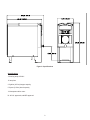
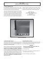
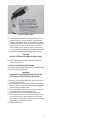
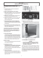
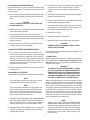
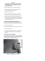
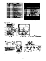
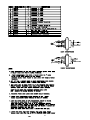
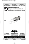
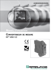
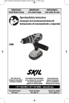
SC118 - Stowaway Slush/Cocktail
OWNER’S MANUAL
Manual No. 513556 Jan., 2001 Rev. 0
Need Parts or Service?
We stock the parts you need.
Our Technicians are factory
trained and are certified in the
Stoelting Technicare program.
CALL
Distributor: _________________________
Phone No.:
_________________________
(fill in or affix label)
Model No.: _______________________
Serial No.: _______________________
Purchase Date: ____________________
Start-Up Date:____________________
OWNER'S MANUAL
FOR MODEL SC118
STOELTING COUNTER MODEL FREEZER
This manual provides basic information about the freezer. Instructions and suggestions are given covering its
operation and care.
The illustrations and specifications are not binding in detail. We reserve the right to make changes to the freezer
without notice, and without incurring any obligation to modify or provide new parts for freezers built prior to date
of change.
DO NOT ATTEMPT to operate the freezer until instructions and safety precautions in this manual are read
completely and are thoroughly understood. If problems develop or questions arise in connection with installation,
operation or servicing of the freezer, contact the company at the following location:
STOELTING, LLC
502 Hwy 67
Kiel, WI 53042-1600
Tele: 920-894-2293
Fax: 920-894-7029
TABLE OF CONTENTS
SECTION
DESCRIPTION
PAGE
1. Introduction .................................................................................................................
1
2. Installation Instruction
2.1 Safety Precautions .................................................................................................
2.2 Shipment and Transit..............................................................................................
2.3 Freezer Installation .................................................................................................
2.4 Installing Permanent Wiring ....................................................................................
3
3
3
4
3. Initial Set-Up and Operation
3.1 Operator's Safety Precautions ................................................................................
3.2 Operating Controls and Indicators...........................................................................
3.3 Disassembly of Freezer Parts ................................................................................
3.4 Cleaning the Freezer Parts .....................................................................................
3.5 Sanitize Freezer and Freezer Parts ........................................................................
3.6 Assembly of Freezer ..............................................................................................
3.7 Sanitizing ...............................................................................................................
3.8 Initial Freeze Down and Operation ..........................................................................
3.9 Consistency Adjustment .........................................................................................
5
5
5
7
7
7
7
8
8
4. Maintenance
4.1 Bulb Replacement ..................................................................................................
9
5. Sequence of Operations
5.1 Lights .....................................................................................................................
5.2 Swithces ................................................................................................................
5.3 Safety Circuit ..........................................................................................................
11
11
11
6. Troubleshooting .........................................................................................................
13
LIST OF ILLUSTRATIONS
FIGURE
TITLE
PAGE
1
Model SC118 .........................................................................................................1
2
Specifications ........................................................................................................ 2
3
Leveling Unit ..........................................................................................................3
4
Power Cord ............................................................................................................4
5
Controls ................................................................................................................. 5
6
Disassembling Freezer ..........................................................................................5
7
Front Door and Auger Assembly ............................................................................6
8
Rear Seal Assembly ..............................................................................................6
9
Consistency Control Knob .....................................................................................8
10
Bulb Replacement .................................................................................................9
SECTION 1
INTRODUCTION
The Stowaway is a countertop profit machine. This compact unit fits onto any crowded bar, yet its high
capacity means it will turn out more than seven gallons every hour. And the Stowaway is as versatile
as it is fast, dispensing frozen, pre-mixed or ready-to-serve blends all with the same smooth
consistency.
Figure 1. Model SC118
Stowaway Features
[ Easy plug-in installation.
[ Lighted, moving product and front-mounted flavor label attract attention and merchandise
product.
[ Large 5.5 quart freezing cylinder serves cups, glasses or pitchers.
[ Mix-low warning light notifies when to refill.
[ Night-mode thermostat allows you to schedule cleaning frequency.
[ Front air intake requires less counter space.
[ Belt-drive system means quiet, dependable operation.
[ Torque control ensures consistent quality product.
1
Figure 2. Specifications
Specifications
12 running amps 115/60/1
15-amp fuse
2.5 gallon (9.5 liter) hopper capacity
5.5 quart (5.2 liter) barrel capacity
1/3 horsepower drive motor
UL & C-UL approved, and NSF approved
2
SECTION 2
INSTALLATION INSTRUCTIONS
2.1 SAFETY PRECAUTIONS
Do not attempt to operate the freezer until the safety
precautions and operating instructions in this manual are
read completely and are thoroughly understood.
If danger, warning or caution labels are needed, indicate
the part number, type of label, location of label, and
quantity required along with your address and mail to:
Take notice of all warning labels on the freezer. The labels
have been put there to help maintain a safe working
environment. The labels have been designed to withstand
washing and cleaning. All labels must remain legible for
the life of the freezer. Labels should be checked periodically to be sure they can be recognized as warning labels.
STOELTING, INC.
ATTENTION: Customer Service
502 Hwy. 67
Kiel, Wisconsin 53042
Figure 3. Leveling Unit
2.2 SHIPMENT AND TRANSIT
The freezer has been assembled, operated and inspected
at the factory. Upon arrival at the final destination, the
complete freezer must be checked for any damage which
may have occurred during transit.
2.3 FREEZER INSTALLATION
Installation of the freezer involves moving the freezer close
to its permanent location, removing all crating, setting in
place, assembling parts, and cleaning.
WARNING
DO NOT USE SPIGOT SPOUT AS A HANDLE TO
LIFT OR MOVE THE FREEZER.
With the method of packaging used, the freezer should
arrive in excellent condition. THE CARRIER IS RESPONSIBLE FOR ALL DAMAGE IN TRANSIT, WHETHER
VISIBLE OR CONCEALED. Do not pay the freight bill until
the freezer has been checked for damage. Have the carrier
note any visible damage on the freight bill. If concealed
damage and/or shortage is found later, advise the carrier
within 10 days and request inspection. The customer must
place claim for damages and/or shortages in shipment
with the carrier. Stoelting, Inc. cannot make any claims
against the carrier.
A. Uncrate the freezer.
B. The freezer must be placed in a solid level position. To
level adjust bottom portion of leg.
C. Place all switches in the OFF position.
3
Figure 4. Power Cord
D. Connect the power cord. The plug is designed for 115
volt/15 amp duty. The unit must be connected to a
properly grounded receptacle. The electrical cord furnished as part of the freezer has a three prong grounding type plug. The use of an extension cord is not
recommended. If one must be used, use one with a
size 12 gauge or heavier with a ground wire. Do not use
an adaptor to get around grounding requirements.
CAUTION
DO NOT ALTER OR DEFORM PLUG IN ANY WAY!
E. Install the drip tray, cover and other miscellaneous
parts on the freezer.
2.4 INSTALLING PERMANENT WIRING
If permanent wiring is required by local codes, the following
procedure must be performed.
WARNING
DISCONNECT FREEZER FROM THE SOURCE OF
ELECTRICAL SUPPLY BEFORE SERVICING.
A. Remove the necessary panels to gain access to the
power cord connection.
B. Disconnect the black and white wires from the terminal
block (L1 and common). Disconnect the green ground
wire from the grounding screw.
C. Remove the strain relief connector from the bottom of
the freezer base.Remove the power cord.
D. Install permanent wiring according to local code.
E. Connect black wire to L1 on the terminal block. Connect the white wire to the common on the terminal
block. Connect the green or yellow and green striped
ground wire to the grounding screw.
F. Replace all panels.
4
SECTION 3
INITIAL SETUP AND OPERATION
3.1 OPERATOR'S SAFETY PRECAUTIONS
SAFE OPERATION IS NO ACCIDENT; Observe these
rules:
A. Know the freezer. Read and understand the
Operating Instructions.
B. Notice all warning labels on the freezer.
C. Wear proper clothing. Avoid loose fitting garments,
and remove watches, rings or jewelry which could
cause a serious accident.
D. Maintain a clean work area. Avoid accidents by
cleaning up the area and keeping it clean.
E. Stay alert at all times. Know which switch, push
button or control you are about to use and what
effect it is going to have.
Figure 5. Controls
F. Disconnect electrical cord for maintenance.
Never attempt to repair or perform maintenance on
the freezer until the main electrical power has been
disconnected.
E. High Pressure Cut Out Switch
The high pressure cut out switch is located under the
right side frame about halfway back. Push up to reset.
G. Do not operate under unsafe operating condi
tions. Never operate the freezer if unusual or excessive noise or vibration occurs.
3.2 OPERATING CONTROLS AND INDICATORS
Before operating the freezer, it is required that the
operator know the function of each operating control.
Refer to Figure 8 for the location of the operating
controls on the freezer.
A. Clean OFF ON Switch
The clean off on switch is a three position switch. In
the clean position only the drive and condenser fan
will run. In the ON position the drive and condenser
fan and compressor will run until the proper consistency is reached, then the compressor will stop and
the drive and condenser fan will continue to run.
Figure 6. Disassembling Freezer
3.3. DISASSEMBLY OF FREEZER PARTS
B. Mix Low Light
The mix low light will illuminate when the liquid level
in the hopper is less than 2".
CAUTION
PLACE THE CLEAN OFF ON SWITCH IN THE OFF
POSITION BEFORE DISASSEMBLING FOR
CLEANING OR SERVICING.
C. Standby Serve Switch
The standby switch is a two position switch. In the
standby position mix temperature will be maintained
between 32° and 40°F. In the serve position the
product temperature in the barrel will be determined
by product consistency.
Inspection for worn or broken parts should be made at
every disassembly of the freezer for cleaning or other
purposes. All worn or broken parts should be replaced to
ensure safety to both the operator and the customer and
to maintain good freezer performance and a quality product. Frequency of cleaning must comply with the local
health regulations.
D. Lights Off On Switch
The lights Off On Switch is a two position switch.
When the switch is in the ON position the lights will
illuminate, when the switch is in the off position the
lights will be OFF.
5
Figure 7. Front Door and Auger Assembly
H. Remove all "O" Rings.
To disassemble the freezer, refer to the following steps:
WARNING
DO NOT USE ANY TYPE OF SHARP OBJECT TO
REMOVE THE "O" RINGS.
A. Remove the front door by removing the upper and lower
plastic shrouds then turn off the knobs, and pull the
front door off the studs.
B. Remove the spigot body from the spout by pulling the
horse shoe clip up and out. Then pull the spigot body
out of the spout. Disassemble by turning off the black
plastic knob and removing all loose pieces.
C. Pull the agitator assembly out of the freezer barrel.
D. Keep the rear of the agitator assembly tipped up once
it is clear of the freezer barrel to avoid dropping rear
seal.
E. Remove the front agitator support bearing and the two
agitator blades.
F. Remove the rear seal assembly and disassemble.
G. Wipe socket lubricant from the drive end (rear) of the
agitator with a cloth or paper towel.
Figure 8. Rear Seal Assembly
6
3.4 CLEANING THE FREEZER PARTS
Place all loose parts in a pan or container and take to the
wash sink for cleaning. To clean freezer parts refer to the
following steps:
C. Lubricate the drive end of the agitator (rear) shaft with
a small amout of white socket lubricant. A small
container of socket lubrication is shipped with the
freezer.
A. Place all parts in warm mild detergent water and clean
with brushes provided. Rinse all parts with clean hot
water.
D. Install the two plastic agitator blades onto the agitator.
Install front agitator bearing.
E. Push the auger into the freezer barrel and rotate slowly
until the agitator engages the drive.
CAUTION
DO NOT DAMAGE PARTS BY DROPPING OR
ROUGH HANDLING.
F. Assemble and install the spigot body with "O" Rings
into the spout. Push straight in until the spigot is in
place. Then install the horse shoe clip.
B. Wash the freezer barrel and spout with warm detergent
water and brushes provided.
G. Install door "O" Ring.
C. The exterior should be kept clean at all times to
preserve the lustre of the stainless steel. A mild alkaline
cleaner is recommended. Use a soft cloth or sponge to
apply the cleaner.
H. Install the front door on the freezer.
I. Install the knobs on the freezer studs and tighten.
CAUTION
FINGER TIGHTEN THE KNOBS EVENLY. DO NOT
OVER-TIGHTEN KNOBS.
D. Remove the drip tray and insert. Clean with a soap
solution. Rinse with clean hot water.
3.5 SANITIZE FREEZER AND FREEZER PARTS
Look for the poper seal between the freezer barrel door, "O"
Ring, and front door.
A. Use a sanitizer mixed according to manufacturer's
instructions to provide a 100 parts per million strength
solution. Mix sanitizer in quantities of no less than 2
gallons (7.5 liters) of 120°F water. Allow the sanitizer to
contact the surfaces to be sanitized for 5 minutes. Any
sanitizer must be used only in accordance with the
manufacturer's instructions.
3.7 SANITIZING
Sanitizing must be done after the freezer is clean and just
before filling with mix. Sanitizing the night before is not
effective. However, you should always clean the freezer
and parts after using it.
WARNING
THE UNITED STATES DEPARTMENT OF AGRICULTURE AND FOOD AND DRUG ADMINISTRATION REQUIRE THAT ALL CLEANING AND SANITIZING SOLUTIONS USED WITH FOOD PROCESSING EQUIPMENT BE CERTIFIED FOR THIS
USE. USE "STERA-SHEEN" OR EQUIVALENT.
B. Place all parts in the sanitizing solution, then remove
and let air dry.
3.6 ASSEMBLY OF FREEZER
To assemble the freezer parts, refer to the following steps:
NOTE
Petro-Gel sanitary lubricant or equivalent must be
used when lubrication of parts is specified.
When sanitizing the freezer, refer to local sanitary regulations for applicable codes and recommended sanitizing
products and procedures. The frequency of sanitizing
must comply with local health regulations. Mix sanitizer
according to manufacturer's instructions to provide a 100
parts per million strength solution. Mix sanitizer in quantities of no less than 2 gallons (7.5 liters) of 120°F water.
Allow sanitizer to contact the surfaces to be sanitized for
5 minutes. Any sanitizer must be used only in accordance
with the manufacturer's instructions.
NOTE
The United States Department of Agriculture and
the Food and Drug Administration require that lubricants used on food processing equipment be certified for this use. Use lubricants only in accordance
with the manufacturer's instructions.
A. Assemble all "O" Rings onto parts dry, without lubrica
tion. Then apply a thin film of sanitary lubrication to
exposed surfaces of the "O" Rings. Apply a thin film of
sanitary lubricant on the fron tof the agitator shaft.
NOTE
Stoelting, Inc. has found that STERA-SHEEN
GREEN LABEL SANITIZER AND CLEANER does
an effective job of properly sanitizing and cleaning a
soft serve freezer. We therefore include a sample
with each new freezer. For further information read
the directions on the packet. Other products may
be as effective.
B. Assembly the rear seal assembly onto the agitator. Be
sure the "O" Rings and gaskets are in place before
installing the rear seal.
7
CAUTION
PROLONGED CONTACT OF SANITIZER WITH
FREEZER MAY CAUSE CORROSION OF STAINLESS STEEL PARTS.
In general, sanitizing may be conducted as follows:
A. Prepare 2 gallons (7.5 liters) of sanitizing solution
following manufacturer's instructions.
B. Pour sanitizer into hopper.
C. Place the CLEAN OFF ON switch in the CLEAN
position. Check for leaks around the front door seal.
D. After five mintues, open spigot to drain sanitizing
solution. When solution has drained, place the CLEAN
OFF ON switch in the OFF position. Allow the freezer
barrel to drain completely.
3.8 INITIAL FREEZE DOWN AND OPERATION
This section covers the recommended operating procedures to be followed for the safe operation of the freezer.
A. Sanitize just prior to use.
B. Place the CLEAN OFF ON switch in the OFF position.
C. Fill the hopper with mix.
D. Place the CLEAN OFF ON switch in the ON position.
The product will be ready to serve in about 20-30
minutes.
3.9 CONSISTENCY ADJUSTMENT
The consistency adjustment knob is located next to the
right front leg. Turn clockwise for a thicker product and
counterclockwise for a thinner product. Allow 15-30 minutes for the product to change consistency.
Figure 9. Consistency Control Knob
8
SECTION 4
BULB REPLACEMENT
4.1 LIGHT BULB REPLACEMENT
1. Remove the upper plastic shroud.
2. Remove the four retaining screws from the electrical
panel and tip forward.
3. Grasp faulty bulb and pull out.
4. Push in replacement bulb until it snaps into place.
5. Replace the electrical panel and secure with the four
retaining screws.
6. Replace the plastic shroud.
Figure 10. Light Bulb
9
10
SECTION 5
SEQUENCE OF OPERATIONS
5.1 LIGHTS
On/Off light switch is independent of all other switches.
When on, the light transformer is operational and the lights
illuminate.
5.2 SWITCHES
On/Off/Clean
Switch
Position
Mode
Switch
Position
Clean
Serve
or
Standby
-Drive Motor and Condenser Fan Motor start and run together,
No time limit exists.
-Power Transformer, torque switch, compressor, liquid level
control, and mix low light are non-operational.
On
Serve
-Drive Motor and Condenser Fan start and run together
continuously.
-Power Transformer is on.
-Liquid level control and mix low light are operational.
-With liquid mix or loose slush in the freezing cylinder, the torque
switch is closed. The delay-on-make timer starts the compressor
after a 10-30 second delay.
-When the slush reaches consistency, the torque switch opens
and the compressor immediately shuts off. The drive motor and
condenser fan motor continue to run.
On
Standby
-Power transformer, liquid level control and mix low light are
operational only when the temperature control is closed.
-Drive motor, condenser fan motor, and compressor cycle on and
off with the temperature control (compressor start delays 10-30
seconds).
Sequence of Operations
NOTE
If the temperature control is set too cold, control will default to the torque switch to prevent freeeze-up.
5.3 SAFETY SWITCH
Door Switch - If the front door is removed, the freezer will not function.
Motor Internal Thermostat - If the motor overheats, the freezer will not function.
Warning - The motor internal thermostat automatically resets as the motor cools. The freezer will automatically
restart. Disconnect freezer from power source for servicing.
High Pressure Cutout Switch - If the compressor discharge pressure exceeds 470 PSIG, the freezer will not
function.
11
12
SECTION 6
TROUBLESHOOTING
PROBLEM:
CAUSE
CORRECTION
High Pressure Cutout Switch Tripped.
Dirty condenser.
Clean condenser
Drive motor overload trips.
shuts down when running)
Improper Brix reading.
Refill with product that has Brix reading between 11
and 13.
No mix in product cylinder or low mix in hopper.
Keep product cylinder and hopper full.
Scraper blade missing from agitator.
Replace scraper blade.
Freezer is being overdrawn.
Slow down rate of draw.
Ambient temperature is about 100°F (37.7°C).
Move or direct hot air away from freezer.
Freezer is being overdrawn.
Slow down the rate of draw.
Condenser is dirty.
Clean condenser.
Drive motor overload tripped off.
Turn freezer off for 5 minutes, allow automatic reset.
Agitator stuck or frozen.
Check for locked or bent fingers. Thaw product in
freezer if frozen.
No power to drive motor.
Check wire harness and switches in drive circuit and
repair or replace.
Drive motor is defective.
Check and replace if necessary.
Toggle Switch in Standby
Toggle switch in OFF or CLEAN position.
Place toggle switch in ON position.
No Ice Crystals on Initial Freeze Down
Blown fuse in building or no input power to
freezer.
Check for blown fuse or input power to freezer.
Mix too rich.
Take "Brix" reading. Fill with properly mixed product.
Restricted air flow to freezer.
Air enters lower front and discharges out the top back,
make certain both areas are clear.
Consistency set for too thin a product.
Set consistency to a thicker product.
Spigot "O" rings defective or missing.
Drain mix to below spigot level. Remove spigot, clean,
replace "O" rings as needed, lubricate and install.
Dried mix in spigot assembly.
Drain mix to below spigot level. Remove spigot retainer
and spigot. Disassemble and clean with hot water and
brush. Lubricate, re-assemble and install. Fill with liquid
mix.
(Freezer
Product dispenses incorrectly.
Product is too thin.
Agitator Does Not Rotate
Spigot Leaking or Stuck.
13
14
15
16
17
18
19
20
21
22
23
24
WARRANTY
MIX TRANSFER PUMPS / COCKTAIL / SLUSH
1. Scope:
Stoelting LLC warrants to the first user (the “Buyer”) that the evaporator assembly and compressor (if applicable)
of Stoelting mix transfer pump, cocktail and slush equipment will be free from defects in materials and workmanship under normal use and proper maintenance appearing within five (5) years (two (2) years for “Mirage” equipment), and that all other components of such equipment manufactured by Stoelting will be free from defects in
material and workmanship under normal use and proper maintenance appearing within twelve (12) months after
the date that such equipment is originally installed.
2. Disclaimer of Other Warranties:
THIS WARRANTY IS EXCLUSIVE; AND STOELTING HEREBY DISCLAIMS ANY IMPLIED WARRANTY OF MERCHANTABILITY OR FITNESS FOR PARTICULAR PURPOSE.
3. Remedies:
Stoelting’s sole obligations, and Buyer’s sole remedies, for any breach of this warranty shall be the repair or (at
Stoelting’s option) replacement of the affected component at Stoelting’s plant in Kiel, Wisconsin, or (again, at
Stoelting’s option) refund of the purchase price of the affected equipment, and, during the first ninety (90) days of
the warranty period, deinstallation/reinstallation of the affected component from/into the equipment. Those obligations/remedies are subject to the conditions that Buyer (a) signs and returns to Stoelting, upon installation, the
Warranty Registration Card for the affected equipment, (b) gives Stoelting prompt written notice of any claimed
breach of warranty within the applicable warranty period, and (c) delivers the affected equipment to Stoelting or its
designated service location, in its original packaging/crating, also within that period. Buyer shall bear the cost and
risk of shipping to and from Stoelting’s plant or designated service location.
4. Extensions:
The warranty period for deinstallation/reinstallation of the affected component from/into the equipment is extended
to twelve (12) months on the following models: SO218, SO318, SO328. The warranty period for the drive motor
to be free of defects in materials and workmanship extended to five (5) years on the following models: SO218,
SO318, SO328.
5. Exclusions and Limitations:
This warranty does not extend to parts, sometimes called “wear parts”, which are generally expected to deteriorate
and to require replacement as equipment is used, including as examples but not intended to be limited to o-rings,
hoses, seals and drive belts. All such parts are sold
AS IS.
Further, Stoelting shall not be responsible to provide any remedy under this warranty with respect to any component that fails by reason of negligence, abnormal use, misuse or abuse, use with parts or equipment not manufactured or supplied by Stoelting, or damage in transit.
THE REMEDIES SET FORTH IN THIS WARRANTY SHALL BE THE SOLE LIABILITY
STOELTING AND THE EXCLUSIVE REMEDY OF BUYER WITH RESPECT TO EQUIPMENT SUPPLIED BY STOELTING; AND IN NO EVENT SHALL STOELTING BE LIABLE
FOR ANY INCIDENTAL OR CONSEQUENTIAL DAMAGES, WHETHER FOR BREACH
OF WARRANTY OR OTHER CONTRACT BREACH, NEGLIGENCE OR OTHER TORT,
OR ON ANY STRICT LIABILITY THEORY.
File: Policy Manual/Warrantyslush1