1
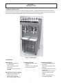
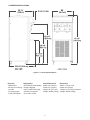
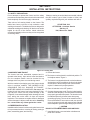
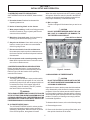
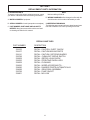
Optima SO328 Floor Model OWNER'S MANUAL Manual No. 513591 Apr. 2003 Rev.2 Need Parts or Service? We stock the parts you need. Our Technicians are factory trained and are certified in the Stoelting Technicare program. CALL Distributor: _________________________ Phone No.: _________________________ (fill in or affix label) Model No.: _______________________ Serial No.: _______________________ Purchase Date: ____________________ Start-Up Date:____________________ OWNER'S MANUAL FOR MODEL SO328 STOELTING FLOOR MODEL FREEZER This manual provides basic information about the freezer. Instructions and suggestions are given covering its operation and care. The illustrations and specifications are not binding in detail. We reserve the right to make changes to the freezer without notice, and without incurring any obligation to modify or provide new parts for freezers built prior to date of change. DO NOT ATTEMPT to operate the freezer until instructions and safety precautions in this manual are read completely and are thoroughly understood. If problems develop or questions arise in connection with installation, operation or servicing of the freezer, contact the company at the following location: STOELTING, LLC 502 Hwy 67 Kiel, WI 53042-1600 Tele: 920-894-2293 Fax: 920-894-7029 TABLE OF CONTENTS SECTION DESCRIPTION PAGE 1. INTRODUCTION 1.1 Remote Possibilities .......................................................................................... 1.2 Features ............................................................................................................ 1.3 Freezer Specifications ....................................................................................... 1 1 2 2. INSTALLATION INSTRUCTIONS 2.1 Safety Precautions ............................................................................................. 2.2 Shipment and Transit ......................................................................................... 2.3 Freezer Installation ............................................................................................. 2.4 Installing Permanent Wiring ................................................................................ 3 3 3 4 3. INITIAL SET-UP AND OPERATION 3.1 Operator's Safety Precautions ............................................................................ 3.2 Operating Controls and Indicators ...................................................................... 3.3 Disassembly of Freezer Parts ............................................................................ 3.4 Cleaning the Freezer Parts ................................................................................ 3.5 Sanitize Freezer and Freezer Parts .................................................................... 3.6 Assembly of Freezer .......................................................................................... 3.7 Sanitizing ........................................................................................................... 3.8 Cleaning & Sanitizing of SO328 with Fill-o-matic II and Fill-o-matic III .................. 3.9 Initial Freeze Down and Operation ..................................................................... 3.10 Removing Product ............................................................................................. 3.11 SO328 Operation ............................................................................................... 5 5 5 6 6 6 7 8 8 8 8 4. PREVENTATIVE MAINTENANCE 4.1 Routine Cleaning ............................................................................................... 4.2 Preventative Maintenance .................................................................................. 4.3 Extended Storage .............................................................................................. 4.4 Consistency Adjustment ..................................................................................... 11 11 11 11 5. REPLACEMENT PARTS INFORMATION 5.1 Ordering Parts ................................................................................................... 5.2 Reference Drawing ............................................................................................ 13 13 6. ACCESSORIES 6.1 Fill-o-matic II ....................................................................................................... 6.2 Fill-o-matic III ...................................................................................................... 6.3 Fill-o-matic Connections .................................................................................... 15 17 19 LIST OF ILLUSTRATIONS FIGURE TITLE PAGE 1 Model SO328 ................................................................................... 1 2 Freezer Specifications ...................................................................... 2 3 Leveling Unit ..................................................................................... 3 4 Electrical Box .................................................................................... 4 5 Controls ............................................................................................ 5 6 Disassembling Freezer ..................................................................... 6 7 Front Door and Auger Assembly ....................................................... 6 8 Rear Seal Assembly ......................................................................... 6 9 Consistency Adjustment .................................................................... 11 10 Fill-o-matic II ..................................................................................... 16 11 Fill-o-matic III ..................................................................................... 18 SECTION 1 INTRODUCTION 1.1 REMOTE POSSIBILITIES The Stoelting Optima delivers frozen drink profits by the pitcher. The Model SO328 is a high-volume producer of ready-to-serve frozen cocktails or frozen neutral base for those special drink recipes. From an extra-small space, the Optima’s compact design and high capacity output will give you extra-large profits. Figure 1. Model SO328 1.2 FEATURES High Capacity - 15-18 gallons per hour per cylinder output - Thick, stackable slush for post-mixing - Or, ready-to-serve pre-mixed products Consistency Control - Adjustable for thick or thin products - Sensitive to product demand - 24 volt control circuits High Efficiency Evaporator/Auger - Stainless steel construction - Long life auger blades - Quiet, smooth operation - 8 qt. freezing cylinder capacity 1 Dispensing Head Door - ”No-Freeze” design prevents blockages - Fast dispense for quick fill of pitchers - Controlled dispense for drinks by the glass - Convenient pull-type handle - Attractive, clear, see-thru design - Visible, moving product for merchandising appeal 1.3 FREEZER SPECIFICATIONS Figure 2. Freezer Specifications Electrical Refrigeration 208/230/60/1 HFC-404A environmentally20 amp circuit & plug friendly refrigerant per side 2 HP (14,800 BTUH) high12 running amps efficiency compressor 1/2 HP Drive Motor Air or water cooled. Crated Dimensions Dimensions Width: 22" (55.9cm) Depth: 30" (76.2cm) Height: 66" (167.7cm) Weight: 400lbs.(182kg) Width: 17.6"(44.7cm) Depth: 26.1"(66cm) Height: 61.2"(155cm) w/casters Weight: 350lbs.(159kg) 2 SECTION 2 INSTALLATION INSTRUCTIONS 2.1 SAFETY PRECAUTIONS Do not attempt to operate the freezer until the safety precautions and operating instructions in this manual are read completely and are thoroughly understood. If danger, warning or caution labels are needed, indicate the part number, type of label, location of label, and quantity required along with your address and mail to: Take notice of all warning labels on the freezer. The labels have been put there to help maintain a safe working environment. The labels have been designed to withstand washing and cleaning. All labels must remain legible for the life of the freezer. Labels should be checked periodically to be sure they can be recognized as warning labels. STOELTING, INC. ATTENTION: Customer Service 502 Hwy. 67 Kiel, Wisconsin 53042 Figure 3. Leveling Unit A. Uncrate the freezer. 2.2 SHIPMENT AND TRANSIT The freezer has been assembled, operated and inspected at the factory. Upon arrival at the final destination, the complete freezer must be checked for any damage which may have occurred during transit. B. The freezer must be placed in a solid level position. To level adjust casters. Figure 3. C. The freezer is equipped with an air cooled condenser and requires correct ventilation; the front is the intake and the back is the discharge. Both front and back require 3" clearance for proper operation. With the method of packaging used, the freezer should arrive in excellent condition. THE CARRIER IS RESPONSIBLE FOR ALL DAMAGE IN TRANSIT, WHETHER VISIBLE OR CONCEALED. Do not pay the freight bill until the freezer has been checked for damage. Have the carrier note any visible damage on the freight bill. If concealed damage and/or shortage is found later, advise the carrier within 10 days and request inspection. The customer must place claim for damages and/or shortages in shipment with the carrier. Stoelting, Inc. cannot make any claims against the carrier. D. Place all switches in the OFF position. E. Connect the two power cords. The plug is designed for 208/230 volt/20 amp duty. The unit must be connected to a properly grounded receptacle. The electrical cord furnished as part of the freezer has a three prong grounding type plug. The use of an extension cord is not recommended. If one must be used, use one with a size 12 gauge or heavier with a ground wire. Do not use an adaptor to get around grounding requirements. 2.3 FREEZER INSTALLATION Installation of the freezer involves moving the freezer close to its permanent location, removing all crating, setting in place, assembling parts, and cleaning. CAUTION DO NOT ALTER OR DEFORM PLUG IN ANY WAY! F. Install the drip tray, cover and other miscellaneous parts on the freezer. 3 2.4 INSTALLING PERMANENT WIRING If permanent wiring is required by local codes, the following procedure must be performed. WARNING DISCONNECT FREEZER FROM THE SOURCE OF ELECTRICAL SUPPLY BEFORE SERVICING. A. Remove the right side and left panels and electrical box covers to gain access to the power cord. B. Remove the strain relief connector from the bottom of the freezer base cut and remove the power cord. C. Install permanent wiring according to local code. Figure 4. Electrical Box D. Connect black wire to black wire. Connect the white wire to white wire. Connect the green or yellow and green striped ground wire to the grounding screw. E. Replace all covers and panels. 4 SECTION 3 INITIAL SETUP AND OPERATION 3.1 OPERATOR'S SAFETY PRECAUTIONS SAFE OPERATION IS NO ACCIDENT; Observe these rules: When the switch is placed in the OFF position, nothing will operate. When the switch in placed in the SERVE position, the agitator and refrigeration system will run until proper consistency is reached then stop. A. Know the freezer. Read and understand the Operating Instructions. C. Mix Low Light The Mix Low light will illuminate when you are low on mix. B. Notice all warning labels on the freezer. C. Wear proper clothing. Avoid loose fitting garments, and remove watches, rings or jewelry which could cause a serious accident. CAUTION DO NOT OPERATE FREEZER WHEN THE LOW MIX LIGHT IS ILLUMINATED OR DAMAGE TO THE FREEZER COULD RESULT. D. Maintain a clean work area. Avoid accidents by cleaning up the area and keeping it clean. Clean Off Serve Switch E. Stay alert at all times. Know which switch, push button or control you are about to use and what effect it is going to have. Pump Off On Switch F. Disconnect electrical cord for maintenance. Never attempt to repair or perform maintenance on the freezer until the main electrical power has been disconnected. Mix Low G. Do not operate under unsafe operating conditions. Never operate the freezer if unusual or excessive noise or vibration occurs. 3.2 OPERATING CONTROLS AND INDICATORS Before operating the freezer, it is required that the operator know the function of each operating control. Refer to Figure 4 for the location of the operating controls on the freezer. Figure 5. Controls 3.3 DISASSEMBLY OF FREEZER PARTS A. Pump OFF/ON Switch The pump OFF/ON Switch is a two position switch. In the OFF position the pump will not run. In the ON position the pump will run until the proper liquid level is reached, then stop. If the hopper does not fill completely, place the switch in the OFF position, then back to ON to continue filling. CAUTION PLACE THE CLEAN/OFF/SERVE SWITCH IN THE OFF POSITION BEFORE DISASSEMBLING FOR CLEANING OR SERVICING. Inspection for worn or broken parts should be made at every disassembly of the freezer for cleaning or other purposes. All worn or broken parts should be replaced to ensure safety to both the operator and the customer and to maintain good freezer performance and a quality product. Frequency of cleaning must comply with the local health regulations. WARNING THE CLEAN/OFF/SERVE SWITCH MUST BE PLACED IN THE OFF POSITION WHEN DISASSEMBLING FOR CLEANING OR SERVICING. THE FREEZER MUST BE DISCONNECTED FROM ELECTRICAL SUPPLY BEFORE REMOVING ANY ACCESS PANEL. To disassemble the freezer, refer to the following steps: B. CLEAN/OFF/SERVE Switch The CLEAN/OFF/SERVE switch is a three position toggle and refrigeration switch used to control the operation of the agitator. When the switch is placed in the CLEAN position, the agitator will rotate. A. Remove hopper cover. B. Remove the front door by turning off the knobs, and then pull the front door off the studs. 5 SOFT RUBBER SURFACE HARD CARBON SURFACE Figure 8. Rear Seal Assembly 3.4 CLEANING THE FREEZER PARTS Place all loose parts in a pan or container and take to the wash sink for cleaning. To clean freezer parts refer to the following steps: Figure 6. Disassembling Freezer C. Remove the spigot body from the front door bypulling the retaining pin out of the spigot handle. Push the spigot body thru the bottom of the front door. A. Place all parts in warm (120°F) mild detergent (Joy or equivalent) water and clean with brushes provided. Rinse all parts with clean hot (135°F) water. D. Remove the agitator assembly from the freezer. Pull the agitator assembly out of the freezer barrel. CAUTION DO NOT DAMAGE PARTS BY DROPPING OR ROUGH HANDLING. E. Keep the rear of the agitator assembly tipped up once it is clear of the freezer barrel to avoid dropping rear seal. B. Wash the freezer barrel with warm (120°F) detergent (Joy or equivalent) water and brushes provided. F. Remove the front agitator support bearing and the two agitator blades. C. The exterior should be kept clean at all times to perserve the lustre of the stainless steel. A mild alkaline cleaner is recommended. Use a soft cloth or sponge to apply the cleaner. G. Remove the rear seal assembly. H. Wipe socket lubricant from the drive end (rear) of the agitator with a cloth or paper towel. D. Remove the drip tray insert and drain tray. Clean with a detergent solution (Joy or equivalent). Rinse with clean hot water. I. Remove all “O” Rings. WARNING DO NOT USE ANY TYPE OF SHARP OBJECT TO REMOVE THE “O” RINGS. 3.5 SANITIZE FREEZER AND FREEZER PARTS A. Use a sanitizer mixed according to manufacturer’s instructions to provide a 100 parts per million strength solution. Mix sanitizer in quantities of no less than 4 gallons (15 liters) of 120°F water. Allow the sanitizer to contact the surfaces to be sanitized for 5 minutes. Any sanitizer must be used only in accordance with the manufacturer’s instructions. B. Place all parts in the sanitizing solution, then remove and let air dry. 3.6 ASSEMBLY OF FREEZER To assemble the freezer parts, refer to the following steps: NOTE Petro-Gel sanitary lubricant or equivalent must be used when lubrication of parts is specified. Figure 7. Front Door and Auger Assembly 6 NOTE The United Sates Department of Agriculture and the Food and Drug Administration require that lubricants used on food processing equipment be certified for this use. Use lubricants only in accordance with the manufacturer’s instructions. WARNING THE UNITED STATES DEPARTMENT OF AGRICULTURE AND FOOD AND DRUG ADMINISTRATION REQUIRE THAT ALL CLEANING AND SANITIZING SOLUTIONS USED WITH FOOD PROCESSING EQUIPMENT BE CERTIFIED FOR THIS USE. USE “STERA-SHEEN” OR EQUIVALENT. A. Assemble spigot “O” Rings onto parts dry, without lubrication. Then apply a thin film of sanitary lubrication to exposed surfaces of the “O” Rings. When sanitizing the freezer, refer to local sanitary regulations for applicable codes and recommended sanitizing products and procedures. The frequency of sanitizing must comply with local health regulations. Mix sanitizer according to manufacturer’s instructions to provide a 100 parts per million strength solution. Mix sanitizer in quantities of no less than 4 gallons (15 liters) of 120°F water. Allow sanitizer to contact the surfaces to be sanitized for 5 minutes. Any sanitizer must be used only in accordance with the manufacturer’s instructions. B. Assemble the rear seal assembly onto the agitator. Be sure the “O” Ring is in place before installing the rear seal. Do not lubricate. C. Lubricate the agitator drive (rear) with a small amount of white socket lubricant. A small container of socket lubricant is shipped with the freezer. D. Install the two plastic agitator blades onto the agitator. Install front agitator bearing to the door. NOTE Stoelting, Inc. has found that STERA-SHEEN GREEN LABEL SANITIZER AND CLEANER does an effective job of properly sanitizing and cleaning a soft serve freezer. We therefore include a sample with each new freezer. For further information read the directions on the packet. Other products may be as effective. E. Push the auger into the freezer barrel and rotate slowly until the agitator engages the drive socket. F. Install the spigot body with “O” Rings into the front door from the bottom. Push straight up until the spigot is in place. Place the spigot handle into the spigot and insert the retainer pin. CAUTION PROLONGED CONTACT OF SANITIZER WITH FREEZER MAY CAUSE CORROSION OF STAINLESS STEEL PARTS. G. Install door “O” Ring after lubricating. H. Install the front door on the freezer. I. Install the knobs on the freezer studs. In general, sanitizing may be conducted as follows: CAUTION FINGER TIGHTEN THE KNOBS EVENLY. DO NOT OVER-TIGHTEN KNOBS. A. Prepare 4 gallons (15 liters) of sanitizing solution following manufacturers instructions, then pour into hopper, brush hopper walls, and inside of hopper cover. Look for the proper seal between the freezer barrel door, “O” Ring, and front door. If using an auto fill. Pour sanitizing solution into the mix container, brush mix container, draw tube and pick up hose. Pump sanitizer from mix containers into the freezer hopper. Brush hopper walls, hopper cover, hose adapter and retaining clip. J. Install hopper cover. 3.7 SANITIZING Sanitizing must be done after the freezer is clean and just before filling with mix. Sanitizing the night before is not effective. However, you should always clean the freezer and parts after using it. B. Place the CLEAN/OFF/SERVE switch in the CLEAN position. Check for leaks around the front door seal. C. After five minutes, open spigot to drain sanitizing solution. When solution has drained, place the CLEAN/OFF/SERVE switch in the OFF position. Allow the freezer barrel to drain completely. 7 3.8 CLEANING & SANITIZING OF S0328 WITH FILL-O-MATIC II AND FILL-O-MATIC III 3.11 SO328 OPERATION INFORMATION FOR SERVICE PERSONNEL The SO328 is a cocktail/slush freezer. It is available in 208-230 volt, either air-cooled or water-cooled. The aircooled version has front-to-back airflow requiring three inches of air space in the front and back for proper refrigeration. This unit is not supplied with a pump, however, Stoelting does offer the Fill-O-Matic II (electric) and Fill-O-Matic III (gas) pumps. This freezer is intended for use with non-dairy products only and will produce 15-18 GPH. A. Empty freezer & mix container of product. B. Mix 4 gallons of warm (120°F) detergent (Joy or equivalent) water and pour into mix container, brush mix container, pick up hose and draw tube. Pump detergent water into freezer hopper. C. Mix sanitizer according to manufacturers instructions in quantities no less than 4 gallons. Pour sanitizer into mix container. Brush mix container, hose and draw tube to sanitize. Pump sanitizer into freezer hopper, empty remaining sanitizer from mix container and let air dry. 1. Filling To fill the freezer, pour mix into hopper until full. To fill freezers with the optional Fill-O-Matic pump, connect the pump and turn the pump switch on, electric model or turn the gas on, gas model. Then turn the pump switch on, located on the freezer, this will open the solenoid valve and the freezer will begin to fill. The liquid level control circuit is designed with a fill timer. This timer is designed to shut the compressor off if the top level probe is not satisfied before the timer expires. If the top level probe is not satisfied before the timer times out, it locks the compressor out and freezing will not occur, if this happens, turn the fill switch off and then back on, this will reset the timer. D. Drain detergent & sanitizer solution from the freezer. E. Disassemble freezer according to Section 3, 3.3. F. Clean freezer and parts according to Section 3, 3.4. G. Sanitize freezer & parts according to Section 3, 3.5. H. Assemble per Section 3, 3.6. I. Sanitize per Section 3, 3.7. 2. Operation Once the freezer is full of mix, turn the clean-off-serve switch to the “serve” position. The drive motor will start immediately. The compressor utilizes a 10 second delay-on-make / delay-on-break timer therefore, the compressor will start 10 seconds later. The compressor will continue to run until the drive motor torque switch is satisfied, then after a 10 second delay stop. The drive motor runs continuously in the “serve” or “clean” switch positions. There is no night mode or standby mode. If product is left in the freezer overnight we recommend to simply turn the freezer off. Do not run the freezer in "clean” overnight. Freeze down time will typically be 610 minutes depending on the type of product used and the starting product temperature. 3.9 INITIAL FREEZE DOWN AND OPERATION This section covers the recommended operating procedures to be followed for the safe operation of the freezer. A. Sanitize just prior to use. Ê B. Place the CLEAN/OFF/SERVE switch in the OFF position. C. With the spigot open, pour one cup of mix into the hopper. Allow approximately 8 oz. of sanitizing solution and mix to drain out. Close the spigot and fill the hopper with mix. 3. Pump Operation D. Place the CLEAN/OFF/SERVE switch in the SERVE position. The product will be ready to serve in about 15 minutes. When the mix level in the hopper drops below the bottom level probe, the solenoid valve opens and the pump begins to fill until the top level probe is satisfied. When satisfied, the solenoid valve closes, and pump will continue to run until shut off pressure is reached. The electric pump will run until the pressure reaches the cut-out pressure of the pump. A gas pump will continue to run until the pressure in the mix line equals the gas pressure of the pump. If you wish to use the product in the hopper prior to cleaning, turn the mix pump off and turn the freezer pump switch off. This will disable the fill timer and allow the compressor to continue to run. Be cautioned that once the hopper is empty, the barrel could freeze up. Only run the freezer until the hopper is empty or damage may occur. 3.10 REMOVING PRODUCT Before disassembly, all product must be removed. A. Open spigot and completely drain freezer. B. Prepare not less than 3 gallons of warm detergent water and pour into hopper. (When using auto fill pump thru auto fill). C. Use a brush to clean the hopper then completely drain freezer. 8 4. Fill Timer Operation The timer has ten dip switches, all switches placed in the “on” position are added together to make up the total time delay. This freezer leaves the factory with 64, 128 and 256 in the “on” position, this is a total of 448 seconds. The preset time should be enough to fill the hopper up to the top level probe. Fill time may be dependent on what style pump is employed. The purpose of the timer is to disable the compressor if the mix supply runs out. When the timer expires, the mix low light will illuminate. If the mix low light is illuminated, the compressor is locked out of the electrical circuit and will not run. It may be necessary to change the timer settings to more closely match the pumping capacity of your pump. 9 10 SECTION 4 PREVENTIVE MAINTENANCE 4.1 ROUTINE CLEANING To remove spilled or dried mix from the freezer exterior, simply wash in the direction of the finish with warm soapy water and wipe dry. Do not use highly abrasive materials as they will mar the finish. NOTE If the condenser is not kept clean, loss of refrigeration efficiency will result, causing extended run time or soft product consistency. 4.3 EXTENDED STORAGE Refer to the following steps for storage of the freezer over any long period of shutdown time: 4.2PREVENTATIVE MAINTENANCE It is recommended that a maintenance schedule be followed to keep the freezer clean and operating properly. A. Turn CLEAN/OFF/SERVE switch to the OFF position. WARNING NEVER ATTEMPT TO REPAIR OR PERFORM MAINTENANCE ON FREEZER UNTIL THE MAIN ELECTRICAL POWER HAS BEEN DISCONNECTED. B. Disconnect (unplug) from the electrical supply source. C. Clean thoroughly with a warm detergent all parts that come in contact with the mix. Rinse in clear water and dry all parts. Do not sanitize. A. Daily 1. The exterior should be kept clean at all times to preserve the lustre of the stainless steel. A mild alkaline cleaner is recommended. Use a soft cloth or sponge to apply the cleaner. NOTE Do not let the cleaning or sanitizing solution stand in the hopper or in the freezer barrel during the shutdown period. 2. Remove the drip tray and insert. Clean the drip tray and insert and front of the freezer with a soap solution. D. Remove, disassemble, and clean the front door, and agitator parts. Place the agitator blades and the front agitator support bearing in a plastic bag with a moist paper towel to prevent them from becoming brittle. B. Weekly 4.4 CONSISTENCY ADJUSTMENT The consistency adjustment knob is located behind the back panel. Remove the lower back panel to access. Turn clockwise for a thicker product and counterclockwise for a thinner product. Figure 9. Allow 15-30 minutes for the product to change consistency. 1. Check “O” Rings and rear seal for excessive wear and replace if necessary. 2. Clean filter. To remove lift up and pull bottom out and down, then wash, dry and reinstall. C. Monthly WARNING DO NOT OPERATE FREEZER WITH BACK PANEL REMOVED. CAUTION THE FREEZER HAS AN AIR COOLED CONDENSER AND MUST HAVE PROPER AIR CIRCULATION. FAILURE TO CLEAN THE CONDENSER ON A REGULAR BASIS MAY RESULT IN SERIOUS FREEZER DAMAGE AND COULD VOID FREEZER WARRANTY. 1. Visually inspect the condenser for dirt by shining a light through the coil from the fan side of the condenser. 2. If the condenser is dirty, using compressed air or CO2 tank, blow out the dirt from the fan side of the condenser. 3. An alternative method of cleaning the condenser is to use a condenser brush and vacuum. Figure 9. Consistency Adjustment 11 12 SECTION 5 REPLACEMENT PARTS INFORMATION 5.1 ORDERING PARTS To assure receipt of the proper replacement parts, supply your dealer or distributor with the following information: NOTE Minimum billing is $50.00. D. WIRING DIAGRAMS reflect changes in effect with the Serial Number which are also indicated by a suffix. A. MODEL NUMBER of equipment. B. SERIAL NUMBER of model (stamped on nameplate). 5.2 REFERENCE DRAWINGS The following pages contain reference drawings and parts lists that will aid the user when operating the freezer. C. PART NUMBER, PART NAME, AND QUANTITY NEEDED. Many part names and numbers are listed on drawings included in this manual. DECALS AND TAGS PART NUMBER 324105 324107 324141 324798 324208 324393 324509 324566 324686 324689 324799 324801 DESCRIPTION DECAL - CAUTION: ELECT. SHOCK DECAL - CAUTION MOVING PARTS DECAL - CAUTION: ROTATING BLADES DECAL - CLEAN-OFF-SERVE SWITCH DECAL - REFRIG. LEAK CHECK DECAL - STOELTING SWIRL LOGO DECAL - CLEANING DECAL - WIRED ACCORDING TO . . . DECAL - DANGER STARTS AUTOMATICALLY DECAL - REAR SEAL ASSEMBLY DECAL - PUMP ON/OFF DECAL - MIX LOW 13 Item Stoelting P/N Qty. 1 2 3 4 5 6 7 8 9 10 11 12 13 14 15 1170882 1 4177009 1 667892 1 3172965 1 624857 1 162157 2 508048 As Reqd 2177118 1 336525-SV 1 625310 1 1171908 1 570196 1 3177001 1 624655 2 2170877 1 Auger Bushing Auger Weldment Seal, Shaft Rear Seal Adapter Ring, O, 2-1/4 ID x 2-5/8 OD x 3/16 CS Blade, Scraper Lubricant Washer, Acetron 1.25 OD x .94 ID x .060" Door, Front Ring, Quad 5.75 ID Pin, Door Pin, 1/4 x 2-1/2 Cotterless Spigot Ring, O, 1 x 1-1/4 x 1/8 70 Duro Handle, Spigot 14 Description SECTION 6 ACCESSORIES 6.1 Fill-O-Matic II The Fill-O-Matic II is a self contained auto-fill system designed to be used with the Model SO328 Freezer. The pump is built onto the cover of a 10 gallon mix vat. A draw tube extends to the bottom of the container to supply the pump with mix, the mix then passes thru a screen, thru the pump and discharges thru a hose to the freezer. The pump is controlled by a pressure switch. The pump starts at 45 PSI and stops at 60 PSI. Cleaning 1. Empty mix container completely. 2. Pour 2 gallons of quite warm detergent water into the mix container and pump thru the pump and hoses. NOTE Do not allow the pump to run dry for more than a few minutes to prevent damage to the pumps components. 3. Remove the strainer by turning counter clockwise, then thoroughly clean. 4. Apply a film of petro-gel to the male threads and "o" ring before reassembly. Do not over tighten. Sanitizing 1. Use a sanitizer mixed according to manufacturers instructions to provide a 100 parts per million strength solution. Mix sanitizer in quantities of no less than 2 gallons (7.5 liters) of 120° water. Allow the sanitizer to contact the surfaces to be sanitized for 5 minutes. Any sanitizer must be used only in accordance with the manufacturers instructions. 2. Pour the sanitizer into the mix container and pump thru the pump and hoses. 3. Make sure all the sanitizer has been pumped out and the container is completely empty, then fill with mix and start the pump pushing out any sanitizer that may be remaining in the hoses. The freezer barrel and hopper can now be filled. 15 On/Off Switch È Ç 115 Volt 15 Amp Plug Figure 10. Fill-o-matic II 16 Å Strainer 6.2 Fill-O-Matic II The Fill-O-Matic III is a gas powered auto-fill system designed to be used with Slush and Cocktail Freezers. The pump is built to hang on the side of a 10 gallon mix vat. The pump can be driven by either regulated CO2, nitrogen or filtered compressed air. A draw tube extends to the bottom of the container to supply the pump with mix, the mix then passes thru the pump and discharges thru a hose to the freezer. The pump is controlled by pressure in the mix line verses gas pressure to the pump. Set the gas pressure to the pump between 20 to 40 PSIG. Cleaning 1. Empty mix container completely. 2. Pour 2 gallons of quite warm detergent water into the mix container and pump thru the pump and hoses. NOTE Do not allow the pump to run dry for more than a few minutes to prevent damage to the pumps components. Sanitizing 1. Use a sanitizer mixed according to manufacturers instructions to provide a 100 parts per million strength solution. Mix sanitizer in quantities of no less than 2 gallons (7.5 liters) of 120° water. Allow the sanitizer to contact the surfaces to be sanitized for 5 minutes. Any sanitizer must be used only in accordance with the manufacturers instructions. 2. Pour the sanitizer into the mix container and pump thru the pump and hoses. 3. Make sure all the sanitizer has been pumped out and the container is completely empty, then fill with mix and start the pump pushing out any sanitizer that may be remaining in the hoses. The freezer barrel and hopper can now be filled. 17 Ë Mix Outlet Gas Ë Outlet Ë Gas Inlet É Figure 11. Fill-o-matic III 18 Mix Inlet 6.3 Fill-O-Matic Connections Gas Powered 7 = To Freezer Electric 6 From Auto Fill Note: Tubing Sold Separately 19 WARRANTY MIX TRANSFER PUMPS / COCKTAIL / SLUSH 1. Scope: Stoelting LLC warrants to the first user (the “Buyer”) that the evaporator assembly and compressor (if applicable) of Stoelting mix transfer pump, cocktail and slush equipment will be free from defects in materials and workmanship under normal use and proper maintenance appearing within five (5) years (two (2) years for “Mirage” equipment), and that all other components of such equipment manufactured by Stoelting will be free from defects in material and workmanship under normal use and proper maintenance appearing within twelve (12) months after the date that such equipment is originally installed. 2. Disclaimer of Other Warranties: THIS WARRANTY IS EXCLUSIVE; AND STOELTING HEREBY DISCLAIMS ANY IMPLIED WARRANTY OF MERCHANTABILITY OR FITNESS FOR PARTICULAR PURPOSE. 3. Remedies: Stoelting’s sole obligations, and Buyer’s sole remedies, for any breach of this warranty shall be the repair or (at Stoelting’s option) replacement of the affected component at Stoelting’s plant in Kiel, Wisconsin, or (again, at Stoelting’s option) refund of the purchase price of the affected equipment, and, during the first ninety (90) days of the warranty period, deinstallation/reinstallation of the affected component from/into the equipment. Those obligations/remedies are subject to the conditions that Buyer (a) signs and returns to Stoelting, upon installation, the Warranty Registration Card for the affected equipment, (b) gives Stoelting prompt written notice of any claimed breach of warranty within the applicable warranty period, and (c) delivers the affected equipment to Stoelting or its designated service location, in its original packaging/crating, also within that period. Buyer shall bear the cost and risk of shipping to and from Stoelting’s plant or designated service location. 4. Extensions: The warranty period for deinstallation/reinstallation of the affected component from/into the equipment is extended to twelve (12) months on the following models: SO218, SO318, SO328. The warranty period for the drive motor to be free of defects in materials and workmanship extended to five (5) years on the following models: SO218, SO318, SO328. 5. Exclusions and Limitations: This warranty does not extend to parts, sometimes called “wear parts”, which are generally expected to deteriorate and to require replacement as equipment is used, including as examples but not intended to be limited to o-rings, hoses, seals and drive belts. All such parts are sold AS IS. Further, Stoelting shall not be responsible to provide any remedy under this warranty with respect to any component that fails by reason of negligence, abnormal use, misuse or abuse, use with parts or equipment not manufactured or supplied by Stoelting, or damage in transit. THE REMEDIES SET FORTH IN THIS WARRANTY SHALL BE THE SOLE LIABILITY STOELTING AND THE EXCLUSIVE REMEDY OF BUYER WITH RESPECT TO EQUIPMENT SUPPLIED BY STOELTING; AND IN NO EVENT SHALL STOELTING BE LIABLE FOR ANY INCIDENTAL OR CONSEQUENTIAL DAMAGES, WHETHER FOR BREACH OF WARRANTY OR OTHER CONTRACT BREACH, NEGLIGENCE OR OTHER TORT, OR ON ANY STRICT LIABILITY THEORY. File: Policy Manual/Warrantyslush1