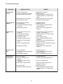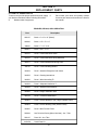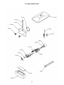
1
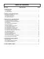
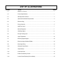
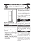
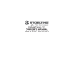
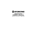
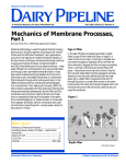
O111 IntelliTec Models
OWNER’S MANUAL
Manual No. 513588-1
Sept. 2006
Owner's Manual
For O111
Stoelting Counter Model Gravity Freezer
Shake and Frozen Beverage
This manual provides basic information about the freezer. Instructions and suggestions are given
covering its operation and care.
The illustrations and specifications are not binding in detail. We reserve the right to make changes
to the freezer without notice, and without incurring any obligation to modify or provide new parts for
freezers built prior to date of change.
DO NOT ATTEMPT to operate the freezer until instructions and safety precautions in this manual
are read completely and are thoroughly understood. If problems develop or questions arise in
connection with installation, operation, or servicing of the freezer, contact the company at the
following location:
STOELTING, LLC
502 Hwy. 67
Kiel, WI 53042
Ph:
800-558-5807
Fax: 920-894-7029
A Few Words About Safety
Safety Information
Read and understand the entire manual before
operating or maintaining Stoelting equipment.
This Owner's Manual provides the operator with
information for the safe operation and maintenance of
Stoelting equipment. As with any machine, there are
hazards associated with their operation. For this
reason safety is emphasized throughout the manual.
To highlight specific safety information, the following
safety definitions are provided to assist the reader.
The purpose of safety symbols is to attract your
attention to possible dangers. The safety symbols,
and their explanations, deserve your careful attention
and understanding. The safety warnings do not by
themselves eliminate any danger. The instructions or
warnings they give are not substitutes for proper
accident prevention measures.
If you need to replace a part, use genuine Stoelting
parts with the correct part number or an equivalent
part. We strongly recommend that you do not use
replacement parts of inferior quality.
Safety Alert Symbol:
This symbol Indicates danger, warning or caution.
Attention is required in order to avoid serious personal
injury. The message that follows the symbol contains
important information about safety.
Signal Word:
Signal words are distinctive words used throughout
this manual that alert the reader to the existence and
relative degree of a hazard.
WARNING
The signal word “WARNING” indicates a potentially
hazardous situation, which, if not avoided, may result
in death or serious injury and equipment/property
damage.
CAUTION
The signal word “CAUTION” indicates a potentially
hazardous situation, which, if not avoided, may result
in minor or moderate injury and equipment/property
damage.
CAUTION
The signal word “CAUTION” not preceded by the safety
alert symbol indicates a potentially hazardous situation, which, if not avoided, may result in equipment/
property damage.
NOTICE
The signal word “NOTICE” indicates information or
procedures that relate directly or indirectly to the
safety or personnel or equipment/property.
TABLE OF CONTENTS
SECTION
DESCRIPTION
PAGE
1. INTRODUCTION
1.1 Description .............................................................................................................
1.2 Specifications ........................................................................................................
1
1
2. INSTALLATION INSTRUCTIONS
2.1 Safety Precautions .................................................................................................
2.2 Shipment and Transit..............................................................................................
2.3 Freezer Installation .................................................................................................
3
4
4
3. INITIAL SET-UP AND OPERATION
3.1 Operator's Safety Precautions ................................................................................
3.2 Operating Controls and Indicators...........................................................................
3.3 Sanitizing ...............................................................................................................
3.4 Freeze Down and Operation ...................................................................................
3.5 Mix Information .......................................................................................................
3.6 Removing Mix From Freezer ..................................................................................
3.7 Cleaning The Freezer .............................................................................................
3.8 Disassembly of Freezer Parts ................................................................................
3.9 Cleaning The Freezer Parts ....................................................................................
3.10 Sanitize Freezer and Freezer Parts .......................................................................
3.11 Assembly of Freezer .............................................................................................
3.12 Routine Cleaning ...................................................................................................
3.13 Preventive Maintenance ........................................................................................
3.14 Extended Storage .................................................................................................
3.15 Product Consistency Adjustment ...........................................................................
3.16 Locking Out Control Panel .....................................................................................
5
5
7
8
9
9
9
9
10
11
11
12
12
14
15
15
4. TROUBLESHOOTING CHARTS
4.1 Error Codes ............................................................................................................
4.2 Troubleshooting Error Codes ..................................................................................
4.3 Troubleshooting Charts ...........................................................................................
17
17
19
5. REPLACEMENT PARTS ...........................................................................................
21
LIST OF ILLUSTRATIONS
FIGURE
TITLE
PAGE
1-1
Model O111 Freezer .............................................................................................. 1
1-2
Freezer Specifications ........................................................................................... 1
2-1
Warning Label Locations ....................................................................................... 3
2-2
Space and Ventilation Requirements ..................................................................... 4
2-3
Electrical Plug ....................................................................................................... 4
3-1
Freezer Controls .................................................................................................... 5
3-2
IntelliTec Control .................................................................................................... 7
3-3
Mix Inlet Regulator ................................................................................................. 7
3-4
Sanitizing Hopper .................................................................................................. 8
3-5
During Freezing Cycle ........................................................................................... 8
3-6
Auger Flight Wear ..................................................................................................10
3-7
Removing Auger Support .......................................................................................10
3-8
Removing Auger Shaft and Flights ......................................................................... 10
3-9
Removing O-Ring ...................................................................................................10
3-10
Cleaning Freezer Barrel .........................................................................................11
3-11
Auger Springs ........................................................................................................11
3-12
Front Door Parts .................................................................................................... 12
3-13
Product Consistency Control .................................................................................15
3-14
Locked Control Display (In Serve Mode) .................................................................15
SECTION 1
DESCRIPTION AND SPECIFICATIONS
1.1 DESCRIPTION
The Stoelting Optima 111 counter freezer is gravity fed. The
freezer is equipped with fully automatic controls to provide
a uniform product. The freezer is designed to operate with
almost any type of commercial soft serve or non-dairy mix
available, including ice milk, ice cream, yogurt, and frozen
dietary desserts. This manual is designed to assist qualified service personnel and operators in the installation,
operation and maintenance of the Stoelting O111 gravity
freezer.
Figure 1-1 Model O111 Freezer
Figure 1-2 Freezer Specifications
1
MODEL OPTIMA 111
COUNTER MODEL
GRAVITY FREEZER
DIMENSIONS:
Freezer: 19" (50.2 cm) wide x 31.5" (80 cm) deep x 37.5" (95.2 cm) high
Crated: 28.75" (73 cm) wide x 38.75" (98.4 cm) deep x 43" (109.2 cm) high
WEIGHT:
Freezer: 310 lbs (140.5 kg)
Crated: 380 lbs. (172.4 kg)
ELECTRICAL:
Description
Optima 111
Voltage AC
1 PH 208/230V
Total Run Amps
13.00
Drive Motor
1.5 HP
Use 20 amp HACR circuit breaker.
Automatic safeguard circuit built into electronic control-protects major
freezer components under abnormal operating conditions.
COOLING:
Air cooled requires minimum 3" (7.6 cm) air clearance on right and left hand side.
No clearance needed in the rear.
Water cooled required 3/8" I.D. water supply line and 3/8" I.D. drain line minimum.
HOPPER:
6.5 Gallons (24.6 liters) refrigerated and insulated.
2
SECTION 2
INSTALLATION INSTRUCTIONS
2.1 SAFETY PRECAUTIONS
If danger, warning or caution labels are needed, indicate
the part number, type of label, location of label, and quantity
required along with your address and mail to:
Do not attempt to operate the freezer until the safety
precautions and operating instructions in this manual are
read completely and are thoroughly understood.
STOELTING, INC.
ATTENTION: Customer Service
502 Hwy. 67
Kiel, Wisconsin 53042
Take notice of all warning labels on the freezer. The labels
have been put there to help maintain a safe working
environment. The labels have been designed to withstand
washing and cleaning. All labels must remain legible for the
life of the freezer. Labels should be checked periodically to
be sure they can be recognized as warning labels.
Figure 2-1 Warning Label Locations
3
2.2 SHIPMENT AND TRANSIT
D.
Place the OFF-ON switch in the OFF position.
The freezer has been assembled, operated and inspected
at the factory. Upon arrival at the final destination, the
complete freezer must be checked for any damage which
may have occurred during transit.
E.
Connect the power cord to the proper power
supply. The plug is designed for 208 or 230 volt/20
amp duty. Check the nameplate on your freezer for
proper supply. The unit must be connected to a
properly grounded receptacle. The electrical cord
furnished as part of the freezer has a three prong
grounding type plug (Fig. 2-3). The use of an
extension cord is not recommended, if necessary
use one with a size 12 gauge or heavier with ground
wire. Do not use an adapter to get around grounding
requirement.
With the method of packaging used, the freezer should
arrive in excellent condition. THE CARRIER IS RESPONSIBLE FOR ALL DAMAGE IN TRANSIT, WHETHER VISIBLE OR CONCEALED. Do not pay the freight bill until the
freezer has been checked for damage. Have the carrier note
any visible damage on the freight bill. If concealed damage
and/or shortage is found later, advise the carrier within 10
days and request inspection. The customer must place
claim for damages and/or shortages in shipment with the
carrier. Stoelting, Inc. cannot make any claims against the
carrier.
2.3 FREEZER INSTALLATION
115V
20 Amp
Installation of the freezer involves moving the freezer close
to its permanent location, removing all crating, setting in
place, assembling parts, and cleaning.
A.
Uncrate the freezer.
B.
Accurate leveling is necessary for correct drainage
of freezer barrel and to insure correct overrun.
Place a bubble level on top of the freezer at each
corner to check for level condition. If adjustment is
necessary, level the freezer by turning the bottom
part of each leg in or out. Then separate freezer
base gasket and install with seam to the back and
angle to the top.
C.
208/230V
20 Amp
Figure 2-3 Electrical Plug
WARNING
Do not alter or deform electrical plug in any way.
Altering the plug to fit into an outlet of different configuration may cause fire, risk of electrical shock,
product damage and will void warranty.
If the freezer is equipped with an air cooled
condenser, correct ventilation is required. The right
side of the freezer is the air intake and left side
discharge. Both sides must have 3" clearance the
top requires 10" of clearance.
F.
CAUTION
Failure to provide adequate ventilation will void warranty.
Figure 2-2 Space and Ventilation Requirements
4
Install the drip tray, drain tray, hopper cover and
other miscellaneous parts on the freezer.
SECTION 3
INITIAL SETUP AND OPERATION
G.
3.1 OPERATOR’S SAFETY PRECAUTIONS
SAFE OPERATION IS NO ACCIDENT; observe these
rules:
Do not operate under unsafe operating conditions.
Never operate the freezer if unusual or excessive
noise or vibration occurs.
A.
Know the freezer. Read and understand the
Operating Instructions.
B.
Notice all warning labels on the freezer.
C.
Wear proper clothing. Avoid loose fitting garments,
and remove watches, rings or jewelry which could
cause a serious accident.
D.
Maintain a clean work area. Avoid accidents by
cleaning up the area and keeping it clean.
WARNING
E.
Stay alert at all times. Know which switch, push
button or control you are about to use and what
effect it is going to have.
F.
Disconnect electrical cord for maintenance. Never
attempt to repair or perform maintenance on the
freezer until the main electrical power has been
disconnected.
High voltage will shock, burn or cause death. The
OFF-ON switch must be placed in the OFF position
prior to disassembling for cleaning or servicing. Do
not operate machine with cabinet panels removed.
3.2 OPERATING CONTROLS AND INDICATORS
Before operating the freezer, it is required that the operator
know the function of each operating control. Refer to
Figure 3-1 for the location of the operating controls on the
freezer.
Dispense Rate Adjustor
Main Power OFF-ON
IntelliTec Control
(See Figure 3-2)
Figure 3-1 Freezer Controls
5
A.
Spigot Switch
The MIX LOW message will appear on the LCD
display to alert the operator to a low mix condition.
The message will display when there is
approximately one gallon of mix left in the hopper.
When the MIX LOW message is displayed, refill
hopper immediately.
The spigot switch will automatically actuate the
auger drive and refrigeration systems when the
spigot is opened to dispense product. When the
spigot is closed, the drive motor and compressor
will remain “on” until the product in the barrel
reaches the proper consistency.
B.
NOTE
Main Freezer Power OFF-ON Switch
Failure to refill hopper immediately may result in
operational problems.
The Main Freezer Power OFF-ON switch is a two
position toggle switch used to supply power to the
control circuit. When the switch is in the OFF
position, power will not be supplied to the control
board or refrigeration system. When the switch is
in the ON position, the freezer will operate in the
freezing mode or cleaning mode. The freezer will
be in the sleep mode until a switch is activated.
C.
G.
The dispense rate adjuster limits the opening of
the spigot. To adjust product dispense rate, turn
the adjusting knob clockwise for slower flow and
counterclockwise for faster flow. It takes at least
five complete turns of the adjusting knob to make
a noticeable difference in the dispense rate.
PUSH TO FREEZE Button
H.
The PUSH TO FREEZE button is used to initiate
the serve mode. To start the freezer, place the
Main Freezer Power OFF-ON switch in the ON
position and press the PUSH TO FREEZE button.
I.
After the drive motor starts, there is a 3 second delay before the compressor starts.
LEDs
The membrane switch features two lights; a green
LED and an amber LED. The green LED is lit
during serve mode. During freeze down, the green
LED is not lit. When product consistency
approaches 75% in the freezing cylinder, the
green LED flashes. The amber LED is lit during all
other modes. In the event of an error or when the
freezing cylinder is off, both LEDs will alternatively
flash.
NOTE
If the freezer shuts off, and alternating green and
amber lights are flashing, the freezer is in an error
condition. If the LCD displays an error, turn the Main
Freezer Power OFF-ON switch to the OFF position, correct the problem (Refer to Troubleshooting
in Section 4) and turn the freezer back on.
E.
CLEAN Button
The CLEAN button will stop all refrigeration and
start auger rotation. A CLEAN message will display
on the LCD screen and a 5 minute timer begins.
To exit the CLEAN mode, press the CLEAN
button again. If the freezer is left in CLEAN for
more than 20 minutes, it will go into an error to
prevent damage to the freezing cylinder. When
this error occurs, refrigeration will start to prevent
mix spoilage. To reset, place the Main Freezer
Power OFF-ON switch in the OFF position and
back in the ON position.
F.
FRONT DOOR SAFETY SWITCH
The front door safety switch prevents the auger
from turning when the front door is removed. The
switch is open when the door is not in place and
closed when the door is properly installed.
NOTE
D.
DISPENSE RATE ADJUSTERS
Mix Low Light Indicator
6
MENU NAVIGATION BUTTONS
Push to Freeze
tions for applicable codes and recommended sanitizing
products and procedures. The frequency of sanitizing
must comply with local health regulations.
Green Light
Mix sanitizer according to manufacturer’s instructions to
provide a 100 parts per million strength solution. Mix
sanitizer in quantities of no less than 2 gallons (7.5 liters)
of 90° to 110°F (32° to 43°C) water. Allow sanitizer to
contact the surfaces to be sanitized for 5 minutes. Any
sanitizer must be used only in accordance with the
manufacturer’s instructions.
Amber Light
Clean Switch
SEL Button
SET Button
Left Arrow Button
CAUTION
Up Arrow Button
Do not allow sanitizer to remain in contact with stainless steel freezer parts for prolonged periods. Prolonged contact of sanitizer with freezer may cause
corrosion of stainless steel parts.
Figure 3-2 IntelliTec Control
The Menu Navigation Buttons allow the user to
display information regarding the freezer's status
of operation as well as adjust product consistency.
In general, sanitizing may be conducted as follows:
Selection Button (SEL) The SEL button is not
functional in the normal operation mode. This
button is only used by service technicians for
freezer calibration.
Set Button (SET) Pressing this button will save a
change made to the product consistency setting.
Refer to Section 3-15 for consistency adjustment
procedures.
Left Arrow Button (Õ) Pressing any button on
the control panel will automatically illuminate the
display. The backlight will turn off several seconds
after use. To keep the display constantly lit, press
and hold the left (Õ) button for five seconds. The
backlight function can be reset to normal operation
in the same manner.
A.
Prepare Stera-Sheen Green Label Sanitizer or
equivalent according to manufacturer’s
instructions to provide a 100ppm strength solution.
Mix the sanitizer in quantities of no less than 2
gallons of 90° to 110°F (32° to 43°C) water. Any
sanitizer must be used only in accordance with
the manufacturer’s instructions.
B.
Push the mix inlet regulator into hopper with air
inlet (long) tube toward the front of the freezer
(Fig. 3-3).
C.
Place the Main Freezer Power OFF-ON toggle
switch in the ON position and press the CLEAN
switch. Check for leaks.
Up Arrow Button (×) Pressing this button will
change the value of the product consistency.
Refer to Section 3-15 for consistency adjustment
procedures.
3.3 SANITIZING
Sanitizing must be done after the freezer is cleaned and
just before the hopper is filled with mix. Sanitizing the night
before is not effective. However, you should always clean
the freezer and parts after each use.
THE UNITED STATES DEPARTMENT OF AGRICULTURE AND THE FOOD AND DRUG ADMINISTRATION REQUIRE THAT ALL CLEANING AND
SANITIZING SOLUTIONS USED WITH FOOD
PROCESSING EQUIPMENT BE CERTIFIED FOR
THIS USE.
Figure 3-3 Mix Inlet Regulator
When sanitizing the freezer, refer to local sanitary regula-
7
E.
The freezer barrel will automatically fill until it is
about 1/2 full. If freezer barrel does not fill, check
for obstruction in the mix inlet regulator. If freezer
barrel fills over 1/2 full, indicated by low overrun,
check for leaks at the mix inlet regulator o-ring or
check if the mix inlet regulator was installed
correctly or that the freezer is level.
F.
Place the Main Freezer Power OFF-ON switch in
the ON position, then press the PUSH TO FREEZE
switch.
NOTE
After the drive motor starts, there is a 3 second delay before the compressor starts.
G.
After about 6 to 10 minutes the product will be at
consistency and the LCD screen will display
"SERVE". The product is ready to serve. Freeze
down time may be longer for some frozen diet
dessert mixes. High ambient temperatures may
extend freeze down time.
H.
For normal dispensing, pull the spigot handle
down to fully open the spigot.
Figure 3-4 Sanitizing Hopper
D.
E.
Clean sides of hopper, mix inlet regulator and
underside of hopper cover using a sanitized soft
bristle brush dipped in the sanitizing solution. (Fig.
3-4).
NOTE
Refrigeration is automatically activated when the
spigot is opened. Close the spigot completely after
dispensing.
After five minutes, place a bucket under the spigot
and open spigot to drain sanitizing solution. When
solution has drained, press the CLEAN button to
stop the auger. Allow the freezer barrel to drain
completely.
I.
3.4 FREEZE DOWN AND OPERATION
The freezer is designed to dispense the product at
a reasonable draw rate. If the freezer is overdrawn,
the result is a soft product or a product that will not
dispense at all. If this should occur, wait until the
bars fill the lower section of the display (Fig. 3-5).
This section covers the recommended operating procedures to be followed for the safe operation of the freezer.
A.
Sanitize just prior to use.
B.
Place the Main Freezer Power OFF-ON switch in
the OFF position.
NOTE
Make sure the mix inlet regulator is in place before
adding mix.
C.
With spigot open, pour approximately 1 gallon
(3.8 liters) of fully thawed mix into the hopper.
Allow the mix to flush out about 8 ounces (0.23
liters) of sanitizing solution and liquid mix. Close
the spigot.
D.
Fill hopper with approximately 3 gallons (11.4
liters) of pre-chilled (40°F or 4°C) mix.
NOTE
Do not overfill the hopper. Mix level must not be
higher than the air inlet tube on the mix inlet regulator.
Figure 3-5 During Freezing Cycle
8
J.
Do not operate the freezer when the MIX LOW
light is on or with less than 1-3/4 inches (4.4 cm)
of mix in the hopper. Refill the hopper immediately.
3.7 CLEANING THE FREEZER
NOTE
The frequency of cleaning the freezer and freezer
parts must comply with local health regulations.
NOTE
The freezer has standby and sleep modes. When
the freezer is not used, after a preset number of
freezing cycles, it will enter the standby mode (followed by sleep mode) and remain there until someone draws a product or presses the PUSH TO
FREEZE button. In the sleep mode, the freezer will
keep the product below 41°F (5°C). Sleep modes
are not to be used in place of cleaning and sanitizing. Frequency of cleaning and sanitizing is determined by Federal, State, and local regulatory agencies.
After the mix has been removed from the freezer, the
freezer must be cleaned. To clean the freezer, refer to the
following steps:
A.
Fill the hopper with 2 gallons (7.5 liters) of tap
water.
B.
Place the Main Freezer Power OFF-ON switch in
the ON position and press the CLEAN switch. The
auger will start to rotate.
C.
Allow the water to agitate for approximately 30
seconds.
NOTE
3.5 MIX INFORMATION
If freezer is left in CLEAN for more than 20 minutes,
the display will show an error code. To reset, place
the Main Freezer Power OFF-ON switch in the OFF
position and back in the ON position.
Mix can vary considerably from one manufacturer to
another. Differences in the amount of butterfat content
and quantity and quality of other ingredients have a direct
bearing on the finished frozen product. A change in freezer
performance that cannot be explained by a technical
problem may be related to the mix.
Proper product serving temperature varies from one
manufacturer’s mix to another. Soft serve mixes generally
provide satisfactory product from 18° to 20°F (-7° to -6°C),
shake mixes 24° to 28°F (-4° to -2°C).
When checking the temperature, stir the thermometer in
the frozen product to read the true temperature.
Old mix or mix that has been stored at elevated temperatures will produce poor-quality product with a bad taste and
unacceptable appearance. To retard bacteria growth in
dairy based mixes, the best storage temperature range is
between 36° to 40°F (2.2° to 4.4°C).
Press the CLEAN button to rotate the auger. Allow
the mix to agitate in freezer barrel until the mix has
become a liquid, about 5 minutes.
C.
Drain the liquid mix by opening the spigot. A
bucket or container should be placed under the
spigot to catch the liquid mix.
D.
Place the Main Freezer Power OFF-ON switch in
the OFF position.
Prepare detergent water by mixing 2 oz. of
Palmolive detergent or equivalent in 2 gallons of
90° to 110°F (32° to 43°C) water. Repeat steps A
through D using the detergent solution.
Hazardous Moving Parts
Revolving auger shaft can grab and cause injury.
Place the Main Freezer Power OFF-ON switch in
the OFF position before disassembling for cleaning
or servicing.
To remove the mix from the freezer, refer to the following
steps:
B.
E.
CAUTION
3.6 REMOVING MIX FROM FREEZER
Remove the mix inlet regulator from the hopper by
pulling straight up.
Open the spigot to drain the water. Remember to
place a container under the spigot to catch the
water. When the water has drained, place the
switch in the OFF position. Allow the freezing
cylinder to drain completely.
3.8 DISASSEMBLY OF FREEZER PARTS
Some products tend to foam more than others. If foam
appears in the hopper, skim off with a sanitized utensil and
discard. Periodically, stir the mix in the hopper with a
sanitized utensil to help prevent excess foam.
A.
D.
Inspection for worn or broken parts should be made each
time the freezer is disassembled. All worn or broken parts
should be replaced to ensure safety to both the operator
and the customer and to maintain good freezer performance and a quality product. Check the wear line on the
auger flights on a regular basis (Fig. 3-6) and replace as
needed. Frequency of cleaning must comply with the local
health regulations.
9
Wear Line
Figure 3-6 Auger Flight Wear
To disassemble the freezer, refer to the following steps:
A.
Remove hopper cover and drain tray.
B.
Remove the mix inlet regulator from the hopper by
pulling straight up.
C.
Remove the front door by turning the circular
knobs and then pulling the front door off the studs.
D.
Remove the rosette cap from the front door. Push
the spigot body through the bottom of the front
door and remove.
E.
Remove the front auger support and bushing (Fig.
3-7).
Figure 3-8 Removing Auger Shaft and Flights
J.
Remove all o-rings from parts by first wiping off
the lubricant using a clean paper towel. Then
squeeze the o-ring upward with a dry cloth (Fig. 38). When a loop is formed, roll out of the o-ring
groove.
CAUTION
Do not use any type of sharp object to remove the
o-rings.
Figure 3-7 Removing Auger Support
F.
G.
Remove the auger assembly from the freezer
(Fig. 3-8). Pull the auger out of the freezer barrel
slowly. As the auger is being pulled out, carefully
remove each of the plastic flights with springs.
Figure 3-9 Removing O-Ring
Keep the rear of the auger shaft tipped up once it
is clear of the freezer to avoid dropping rear seal.
H.
Remove the rear seal.
I.
Wipe socket lubricant from the drive end (rear) of
the auger with a cloth or paper towel.
3.9 CLEANING THE FREEZER PARTS
Place all loose parts in a pan or container and take to the
wash sink for cleaning. To clean freezer parts refer to the
following steps:
10
NOTE
The United States Department of Agriculture and
the Food and Drug Administration require that lubricants used on food processing equipment be certified for this use. Use lubricants only in accordance
with the manufacturer’s instructions.
A.
Assemble all o-rings onto parts dry, without
lubrication. Then apply a thin film of sanitary
lubrication to exposed surfaces of the o-rings.
Apply a thin film of sanitary lubricant to metal part
of rear seal. Also apply a thin film of sanitary
lubricant inside and outside of the front auger
support bushing.
B.
Assemble the rear seal onto the auger with the
large end to the rear. Be sure the o-ring is in place
before installing the rear seal.
C.
Lubricate the auger drive (rear) with a small
amount of white socket lubricant. A small container
of socket lubricant is shipped with the freezer.
D.
Screw the springs onto the studs in plastic flights.
Springs must be screwed into the flights completely
to provide proper compression (Fig. 3-10).
Figure 3-10 Cleaning Freezer Barrel
A.
Prepare detergent water by mixing 2 oz. of
Palmolive detergent or equivalent in 2 gallons of
90° to 110°F (32° to 43°C) water. Place all parts
in detergent solution and clean with provided
brushes. Rinse all parts with clean 90° to 110°F
(32° to 43°C) water.
B.
Wash the hopper and freezing cylinder with the
90° to 110°F (32° to 43°C) detergent water and
brushes provided (Refer to Figure 3-9).
C.
Clean the rear seal surfaces from the inside of the
freezing cylinder with the 90° to 110°F (32° to
43°C) detergent water.
D.
CAUTION
Do not place the mix inlet regulator into the hopper
before installing the auger. Attempting to install the
auger with the mix inlet regulator in place will damage the mix inlet regulator.
Clean the drip tray and insert with a soap solution.
Rinse with clean hot water.
3.10 SANITIZE FREEZER AND FREEZER
PARTS
A.
Use a sanitizing solution mixed according to
manufacturer's instructions to provide 100 parts
per million strength solution. Mix sanitizer in
quantities of no less than 2 gallons (7.5 liters) of
120°F water. Allow the sanitizer to contact the
surfaces to be sanitized for 5 minutes. Any sanitizer
must be used only in accordance with the
manufacturer's instructions.
B.
Place all parts in the sanitizing solution, then
remove and let air dry.
C.
Using this sanitizing solution and the large barrel
brush provided, sanitize the rear of the barrel by
dipping the brush in the sanitizing solution and
brushing the rear of the barrel.
Figure 3-11 Auger Springs
3.11 ASSEMBLY OF FREEZER
To assemble the freezer parts, refer to the following steps:
E.
Install the two plastic flights onto rear of the auger
and insert part way into freezer barrel.
F.
Install the remaining plastic flights, push the auger
into the freezer barrel and rotate slowly until the
auger engages the drive shaft.
G.
Install the bushing and auger support into the front
of the auger with one leg of the support pointing
straight up.
NOTE
Petrol Gel sanitary lubricant or equivalent must be
used when lubrication of parts is specified.
11
The following information has been compiled by Purdy
Products Company, makers of Stera-Sheen Green Label
Cleaner/Sanitizer and specifically covers issues for cleaning and sanitizing frozen dessert machines. This information is meant to supplement a comprehensive food safety
program.
Soil Materials Associated with Frozen Dessert
Machines
MILKFAT/BUTTERFAT – As components of ice-cream/
frozen custard mix, these soils will accumulate on the
interior surfaces of the machine and its parts. Fats are
difficult to remove and help attribute to milkstone buildup.
MILKSTONE – Is a white/gray film that forms on equipment and utensils that come in contact with dairy products.
These films will accumulate slowly on surfaces because of
ineffective cleaning, use of hard water, or both. Milkstone
is usually a porous deposit, which will harbor microbial
contaminants and eventually defy sanitizing efforts.
Once milkstone has formed, it is very difficult to remove.
Without using the correct product and procedure, it is
nearly impossible to remove a thick layer of milkstone.
(NOTE: general-purpose cleaners DO NOT remove
milkstone.) This can lead to high bacteria counts and a
food safety dilemma.
Figure 3-11 Front Door Parts
H.
Install the spigot body with o-ring into the front
door from bottom (Fig. 3-11). Push straight up
until the spigot is in place.
I.
Install the front door on the freezer.
J.
Install the circular knobs on the freezer studs.
IT IS BEST TO CONTROL MILKSTONE ON A DAILY
BASIS BEFORE IT CAN BECOME A SIGNIFICANT FOOD
SAFETY PROBLEM.
In addition to food safety, milkstone can cause premature
wear to machine parts which can add to costs for replacement parts or possibly more expensive repairs if worn
machine parts are not replaced once they have become
excessively worn.
CAUTION
Overtightening or uneven tensioning of circular
knobs may cause damage to front door and cause
leaking. Hand tighten circular knobs evenly.
K.
Important Differences Between Cleaning and
Sanitizing
CLEANING vs. SANITIZING
Look for the proper seal between the freezer
barrel, o-ring, and front door.
L.
Install the mix inlet regulator into the freezer with
the air tube to the front of the freezer.
M.
Install hopper cover and drain tray.
It is important to distinguish between cleaning and sanitizing. Although these terms may sound synonymous, they
are not. BOTH are required for adequate food safety and
proper machine maintenance.
CLEANING
3.12 ROUTINE CLEANING
•
Is the removal of soil materials from a surface.
To remove spilled or dried mix from the freezer exterior,
simply wash in the direction of the finish with warm soapy
water and wipe dry. Do not use highly abrasive materials
as they will mar the finish.
•
Is a prerequisite for effective sanitizing.
3.13 PREVENTIVE MAINTENANCE
It is recommended that a maintenance schedule be followed to keep the freezer clean and operating properly.
Bacteria can develop and resist sanitizing efforts within a
layer of soil material (milkstone). Thorough cleaning procedures that involve milkstone removal are critical for
operators of frozen dessert machines.
Cleaning and Sanitizing Information
SANITIZING
Soft serve freezers require special consideration when it
comes to food safety and proper cleaning and sanitizing.
•
Kills bacteria.
•
Can be effective on clean surfaces only.
NOTE
An UNCLEAN surface will harbor bacteria that can
defy sanitizing efforts.
12
NOTE
With proper daily use of STERA-SHEEN or its equivalent,
there is no need for the use of a DELIMER.
Using a SANITIZER on an unclean surface will not
guarantee a clean and safe frozen dessert machine.
DO NOT USE BLEACH
Proper Daily Maintenance: The Only Way to Assure
Food Safety and Product Quality
•
BLEACH HAS ABSOLUTELY NO CLEANING
PROPERTIES.
Proper daily maintenance can involve a wide variety of
products and procedures. Overall, the products and procedures fall into three separate categories. (Please note
that this is a brief overview intended for informational
purposes only.)
•
BLEACH IS CORROSIVE. It can and will damage
components of the machine causing premature wear and
metal corrosion.
1.
2.
3.
GENERAL PURPOSE CLEANERS
General purpose cleaners do not have the ability to remove milkstone. Milkstone will become a problem if not
remedied with additional products and procedures.
CLEANING – This involves draining mix from the
freezer barrel and rinsing the machine with water.
Next, a cleaner is run through the machine. Then,
the machine is disassembled and removable
parts are taken to the sink for cleaning.
THE USE OF CHLORINE TEST STRIPS
“Test strips” are used to determine concentrations of
active chlorine in sanitizing solutions. To use the strips,
tear off a small portion and submerge it into the sanitizing
solution. Then, compare the color change to the color key
on the side of the test strip dispenser to determine the
approximate chlorine concentration.
MILKSTONE REMOVAL – Since almost all
cleaners do not have the ability to remove
milkstone, the use of a delimer becomes
necessary. Although this procedure may not be
needed on a daily basis, it will usually follow the
cleaning procedure. It requires letting a delimer
solution soak in the machine for an extended
period of time. Individual parts are also soaked in
a deliming solution for an extended period of time
(more about delimers in Additional Information).
The ideal concentration of chlorine needs to be 100 ppm
(as stated by the FDA).
NOTE
Follow the directions on the container for proper concentration.
SANITIZING – After the machine has been cleaned
and contains no milkstone, the machine is
reassembled. Then a FDA-approved sanitizing
solution is run through the machine to kill bacteria.
The machine is then ready for food preparation.
There are two main factors that contribute to falling chlorine concentrations in a sanitizing solution.
1.
PRODUCT USE – As the chlorine in the solution
is being used, chlorine concentrations fall.
As a recommended cleaner and sanitizer for your frozen
dessert machine, STERA-SHEEN has proven to be one of
the best daily maintenance products for:
2.
TIME – As time passes, small amounts of chlorine
“evaporate” from the solution. (That is why you
can smell it.)
•
CLEANING – Thorough removal of all solids
including butterfat and milk fat.
Sanitizing solutions should not be allowed to fall below 100
ppm chlorine. New solutions should be mixed once old
solutions become ineffective
•
MILKSTONE REMOVAL – Complete removal of
milkstone.
•
SANITIZING – FDA-approved no rinse sanitizer
for food contact surfaces.
B.
DAILY
1.
The exterior should be kept clean at all times to
preserve the luster of the stainless steel. A mild
alkaline cleaner is recommended. Use a soft cloth
or sponge to apply the cleaner.
Additional Information
THE USE OF DELIMERS
A delimer is a strong acid that has the ability to dissolve
milkstone. This type of chemical may become necessary
once high levels of milkstone have developed. While
these products are very effective for removing HIGH
levels of milkstone, they are not ideal for two reasons:
1.
PRODUCT SAFETY – Strong acids are dangerous
chemicals and handling them requires safety
2.
MACHINE DAMAGE – Strong acids will attack
metal and rubber causing premature wear of
parts. The use of a delimer needs to be closely
monitored to avoid damage to machine surfaces
and parts.
CAUTION
Do not use acidic cleansers, strong caustic compounds or abrasive materials to clean any part of
the freezer exterior or plastic parts. Use of these
types of cleaners will cause equipment damage.
13
C.
WEEKLY
1.
Check o-rings and rear seal for excessive wear
and replace if necessary.
2.
D.
Remove the drip tray by gently lifting up to
disengage from the support and pulling out. Clean
behind the drip tray and front of the freezer with a
soap solution.
QUARTERLY
E.
SEMI-ANNUALLY
1.
Check drive belt for proper tension. Push belt in
with one finger, belt should deflect about 3/8".
2.
Lubricate condenser fan motor with S.A.E. 20
weight oil. Three to six drops is required.
WARNING
CAUTION
High voltage will shock, burn or cause death. Turn
off and lock out main power disconnect before servicing. Do not operate machine with panels removed.
Do not over-lubricate; resulting damage could cause
motor failure.
3.14 EXTENDED STORAGE
The air-cooled condenser is a copper tube and aluminum
fin type. Condensing is totally dependent upon airflow. A
plugged condenser filter, condenser, or restrictions in the
louvered panel will restrict airflow. This will lower the
capacity of the system and damage the compressor.
Refer to the following steps for storage of the freezer over
any long period of shutdown time:
The condenser must be kept clean of dirt and grease. The
freezer must have a minimum of 3” (7.5 cm) of ventilation
on the right and left sides of the unit for free flow of air.
Make sure the freezer is not pulling over 100° F (37° C) air
from other equipment in the area.
A.
Turn the Main Freezer Power OFF-ON switch to
the OFF position.
B.
Disconnect (unplug) from the electrical supply
source.
C.
Clean thoroughly with a warm water detergent all
parts that come in contact with the mix. Rinse in
clean water and dry parts. Do not sanitize.
The water-cooled condenser is a tube and shell type. The
condenser needs a cool, clean supply of water to properly
cool the freezer, inlet and discharge lines must be 3/8” I.D.
minimum.
NOTE
Do not let the cleaning solution stand in the hopper
or in the freezer barrel during the shutdown period.
The condenser and condenser filter require periodic cleaning. To clean, refer to the following procedures.
1.
Remove the Phillips head screw from the bottom
of the right side panel, and then slide the panels
down and out.
2.
To remove the condenser filter, grasp the top and
pull off. Visually inspect for dirt. If the filter is dirty,
shake or brush excess dirt off the filter and wash
in warm, soapy water. Once the filter is clean rinse
thoroughly in warm, clear water and shake dry,
taking care not to damage the filter in any way
(Figure 28).
3.
Visually inspect the condenser for dirt by shining
a light through the coil from the back (inside) of the
condenser.
4.
If the condenser is dirty, place a wet towel over the
front (outside) of the condenser.
5.
Using a vacuum, carefully clean the condenser
coil from the inside and outside of the freezer. A
stiff bristled brush may help in releasing debris
from between the condenser coils.
D.
Remove, disassemble and clean the front door,
mix inlet regulator and auger parts. Place the
auger flights and the front auger support bushing
in a plastic bag with a moist paper towel to prevent
them from becoming brittle.
E.
In a water cooled freezer, disconnect water lines
and drain water. With a flathead screwdriver, hold
the water valve open and use compressed air to
clear the lines of any remaining water.
3.15 PRODUCT CONSISTENCY ADJUSTMENT
The IntelliTec control monitors the consistency (firmness)
of the product (mix) in the freezing cylinder by monitoring
the drive motor amp draw. When consistency is reached,
the drive motor and refrigeration system will shut off. The
control panel on the front of the freezer allows the operator
to adjust the freezing cylinder to create the desired product
consistency.
14
A.
Place the FREEZING CYLINDER OFF/ON switch
in the ON position.
B.
Press the SET button on the Control Panel once.
Fine Adj will appear on the LCD screen (Fig. 312).
C.
Release both buttons. An asterisk (*) will appear
after the word MODE on the display, indicating
that the control is in the lock out mode (Fig. 3-13).
D.
To unlock the control panel, repeat steps A, B and
C.
Fine Adj
5
1-9
Figure 3-13 Product Consistency Control
C.
Press the up arrow button (×) until the desired
consistency setting is displayed. The higher the
number, the greater the product consistency
(firmness). When the digit reaches 9, pressing
the up arrow button (×) again will change the
value to 0. Press SET to save the value. The 0
setting cannot be set.
D.
Press the SET button once to save the setting
change and return to the current mode display.
3.16 LOCKING OUT CONTROL PANEL
The IntelliTec control has a tamper proof mode to prevent
unauthorized use. When set, all buttons on the control
panel are disabled. To lock out the control panel:
A.
Press and hold the PUSH TO FREEZE button for
5 seconds.
B.
While still holding the PUSH TO FREEZE button,
press the CLEAN button once.
SERVE
*
Figure 3-14 Locked Control Display (In Serve Mode)
15
16
SECTION 4
TROUBLESHOOTING
Error Code 3 - Run Time
4.1 ERROR CODES
The Run Time Error (E3) occurs when the
compressor runs continuously for 30 minutes
without the product reaching consistency in “Serve
Mode” or if the product does not reach proper
temperature in “Sleep 2 Mode”. This error is
generally caused by very low mix levels in the
freezer’s mix container or from product breakdown.
Another common cause results from a restriction
preventing mix from entering the freezing cylinder.
Check the mix in the hopper. If the level mix is low,
add mix. If there is a possibility that the mix is
broken down, clean and sanitize the freezer and
replace the mix with fresh product.
When the freezer experiences a problem, one of the
following error codes will be displayed on the control panel.
Each error code directs you to the system location of the
malfunction.
ERROR CODE MALFUNCTION
1
Soft
2
High Torque
3
Extended Run Time
4
Clean
5
Barrel Sensor
6
Hopper Sensor
7
Drive Motor
8
Cab Sensor
9
High Pressure Cutout
10
Auxiliary Sensor
11
Low Temperature
Ice crystals in the hopper can clog the mix inlet
system and prevent mix from entering the freezing
cylinder. Thoroughly thaw mix per manufacturer’s
recommendations. To check for ice crystals, pour
a small amount of product in the hopper through
a clean and sanitized sieve or strainer. If ice
crystals are in the mix, check the temperature of
the walk-in cooler where the mix is stored or the
temperature of the freezer’s cabinet.
To return the freezer to normal operation, any error causing condition must be corrected and the Freezing Cylinder
Off-On switch must be placed in the Off position and back
in the On position before the affected side of the freezer
will return to normal operation.
The Run Time Error may also occur if airflow
within the freezer has reduced or stopped. Check
the sides and top of the freezer for anything that
would restrict airflow.
4.2 TROUBLESHOOTING
If the error persists after attempting to clear it,
contact your Authorized Stoelting Distributor for
further assistance.
Error Code 1 - Soft Error
The Soft Error (E1) is an internal control board
error that is logged for future analysis. The
refrigeration is never stopped and the freezer will
continue to operate normally.
Error Code 4 - Clean
If the freezer is left in the Clean Mode for more
than 20 minutes, the control panel will display a
Clean Error (Error 04). This condition does not
reflect a problem with the freezer itself. The Clean
Error has been programmed into the controller as
a safeguard to protect the freezer from potential
damage caused by the freezer being accidentally
left in “Clean Mode”. The control will attempt to
restart itself after 5 minutes. The display will then
flash and read Restart. To immediately clear the
Clean Error, place the Main Power Off-On switch
in the Off position and back in the On position.
After the Clean Error has been cleared, the freezer
will start a refrigeration cycle to protect the product
in case the clean button was pressed by mistake.
Error Code 2 - High Torque
If the control panel displays a High Torque Error
(E2), the controller has sensed that the drive
motor is running at 125% of the preset CutOut
amp setting for 10 or more seconds. This may be
due to the product consistency adjustment being
set too high. Place the Main Power OFF-ON
switch in the OFF position, wait until the product
in the barrel thaws to a reasonably soft consistency
and return the switch to the ON position. Follow
the instructions in Section 3 to reduce the product
consistency by a few levels. If the error persists,
contact your Authorized Stoelting Distributor for
further assistance.
17
Error Code 5 - Freezing Cylinder Sensor
Error Code 11 - Low Temperature
The Freezing Cylinder Sensor Error (E5) indicates
a failure of the barrel sensor or an extreme out of
range condition (< -34°F or > 99°F). If the control
panel displays an E5, place the Freezing Cylinder
Off-On switch in the Off position and back in the
On position. If the error persists, contact your
Authorized Stoelting Distributor for further
assistance.
The Low Temperature Error (E11) occurs when
the temperature of the gas refrigerant at the barrel
sensor falls below -20°F or -34°F (depending on
model). Although the freezer will not shut down,
the active freezing cycle will immediately end.
This error usually occurs when the freezer
continues to run in a low mix condition or if the
freezer runs out of mix. The product towards the
front of the barrel tends to freeze solid. When the
temperature on the freezing cylinder lowers to the
preset value, the IntelliTec control will display an
E11.
NOTE
When the freezer encounters a Freezing Cylinder
Sensor Error, the freezer will continue to run using
preset timers. This mode will allow the operator to
continue serving product until the freezer can be
serviced.
ALTERNATING FLASHING CONTROL PANEL LIGHTS
The display panel lights will flash in an alternating
sequence under any error codes. Clear the error
and place the Freezing Cylinder Off-On switch in
the Off position and back in the On position.
Error Code 6 - Hopper Sensor (single hopper freezers)
The Hopper Sensor Error (E6) indicates a failure
of the hopper sensor or an extreme out of range
condition (< -34°F or > 99°F). If the control panel
displays an E6, place the Freezing Cylinder OffOn switch in the Off position and back in the On
position. If the error persists, contact your
Authorized Stoelting Distributor for further
assistance.
Error Code 7 - Drive Motor
If the control panel displays a Drive Motor Error
(E7), the control does not sense current coming
from the drive motor. Place the Freezing Cylinder
Off-On switch in the Off position and back in the
On position. If the error persists, contact your
Authorized Stoelting Distributor for further
assistance.
Error Code 8 - Cab Sensor
A Cab Sensor Error (E8) will not occur on the
E111 or F111 freezer.
Error Code 9 - High Pressure Cutout
High Pressure Cutout Errors (E9) are usually
caused by a dirty or inefficient condenser. If the
control panel displays an E9 on an air cooled
freezer, check for proper air clearance around the
freezer. If the error persists, contact your
Authorized Stoelting Distributor for further
assistance.
Error Code 10 - Auxiliary Sensor
An Auxiliary Temperature Sensor Error (R10)
occurs if the temperature sensor on the control
board fails. Place the Freezing Cylinder Off-On
switch in the Off position and back in the On
position. If the error persists, contact your
Authorized Stoelting Distributor for further
assistance.
18
4.3 Troubleshooting Charts
PROBLEM
Freezer does
not run.
POSSIBLE CAUSE
REMEDY
1. Power to freezer is off.
2. Fuse or circuit if blown or tripped.
3. Freeze-up (auger will not turn).
4. High pressure cut-out tripped.
5. Front door not in place.
1. Supply power to freezer.
2. Replace or reset.
3. Turn CLEAN-OFF-ON switch to OFF
(middle) position for 15 minutes, then
restart.
4. Wait for switch to reset (10 minutes).
5. Assemble front door in place.
Freezer will not
shut off.
1. Not enough mix in hopper.
2. Drive belt failure.
3. Consistency temperature setting
is too firm.
4. Refrigeration problem.
1. Fill hopper with mix.
2. Replace drive belt.
3. Turn Consistency Adjustment knob
counter-clockwise.
4. Check system. (Call distributor for
service.)
Product is too
soft.
1. No vent space for free flow of
cooling air.
2. Air temperature entering
condenser is above 100°F.
3. Condenser is dirty.
4. Consistency setting too soft.
1. A minimum of 3 inches of vent space
required. (See Section 2)
2. Change location or direct hot air away
from freezer.
3. Clean. (See Section 3)
4. Turn Consistency Adjustment knob
clockwise.
5. Remove mix, clean, sanitize and freeze
down with fresh mix.
6. Remove mix, clean, reassemble, sanitize
and freeze down.
7. Check system. (Call distributor for
service.)
5. Stabilizers in mix are broken
down.
6. Auger is assembled wrong.
7. Refrigeration problem.
Product is too
firm.
1. No mix in hopper.
2. Consistency temperature setting
is too firm.
3. Line voltage fluctuating.
1. Fill hopper with mix.
2. Turn Consistency Adjustment knob
counter-clockwise.
3. Check. (Call distributor for service.)
Product does
not dispense.
1. No mix in hopper.
2. Mix inlet regulator tube is
plugged.
3. Capacity of freezer is being
exceeded.
4. Drive motor overload tripped.
1. Fill hopper with mix.
2. Unplug, using small sanitized brush.
3. Slow up on the draw rate.
5. Drive belt failure.
6. Freeze-up. (Auger will not turn.)
19
4. Reset. (If condition continues, call
distributor for service.)
5. Replace drive belt.
6. Turn CLEAN-OFF-ON switch to OFF
(middle) position for 15 minutes, then
restart.
4.3 Troubleshooting Charts - continued
PROBLEM
POSSIBLE CAUSE
REMEDY
Drive belt
slipping or
squealing.
1. Worn drive belt.
2. Freeze-up (Auger will not turn).
1. Replace drive belt.
2. Turn CLEAN-OFF-ON switch to OFF
(middle) position for 15 minutes, then
restart.
Low overrun.
1. Auger is assembled wrong.
1. Remove mix, clean, sanitize, and freeze
down with fresh mix.
2. Replace mix inlet regulator.
3. Replace mix inlet regulator o-ring.
2. Mix inlet regulator missing.
3. Mix inlet regulator o-ring
missing.
4. Mix inlet regulator air tube
blocked.
5. Product breakdown.
Rear auger seal
leaks.
4. Clean with sanitized brush.
5. Fill freezer with fresh product.
1. Outside surface of rear auger seal
is lubricated.
2. Rear seal missing or damaged.
3. Seal o-ring missing, damaged or
installed incorrectly.
4. Worn or scratched shaft.
1. Clean lubricant from outside of rear seal,
lubricate inside of seal and reinstall.
2. Check or replace.
3. Check or replace
Front door
leaks.
1. Front door knobs are loose.
2. Spigot parts are not lubricated.
3. Chipped or worn spigot o-rings.
4. O-rings or spigot installed wrong.
5. Inner spigot hole in front door
nicked or scratched.
1. Tighten knobs.
2. See Section 3.
3. Replace o-rings.
4. Remove spigot and check o-ring.
5. Replace front door.
Hopper will not
maintain mix
temperature
below 40°F
(4°C).
1. Hopper temperature set too warm.
2. Refrigeration problem.
1. Call distributor for service.
2. Call distributor for service.
20
4. Replace shaft.
SECTION 5
REPLACEMENT PARTS
5.1 HOW TO ORDER PARTS
B.
Serial number of model, stamped on nameplate
To assure receipt of the proper replacement parts, supply
your dealer or distributor with the following information:
C.
Part number, part name and quantity needed.
Common part names and numbers are listed in
this manual.
A.
Model number of equipment.
BRUSHES, DECALS, AND LUBRICATION
Part
Description
208135
Brush - 4" x 8" x 16" (Barrel)
208380
Brush - 1/4" x 3" x 14"
208401
Brush - 1" X 3" X 10"
208467
Brush - 3/8" x 1" x 5"
324105
Decal - Caution Electrical Shock
324106
Decal - Caution Electrical Wiring Materials
324107
Decal - Caution Hazardous Moving Parts
324141
Decal - Caution Rotating Blades
324208
Decal - Attention Refrigerant Leak Check
324509
Decal - Cleaning Instructions
324566
Decal - Wired According To
324584
Decal - Adequate Ventilation 3"
324594
Decal - Attention Heat Sensitive
324686
Decal - Danger Automatic Start
324728
Decal - Contactor Identification
324803
Decal - Domed Stoelting Logo (Large) (Header Panel)
324804
Decal - Domed Stoelting Swirl (Header Panel)
324825
Decal - Main Freezer Power
508048
Hex Drive Anti Seize (Spline Lubricant) - 2oz. Tube
508135
Petro Gel - 4oz. Tube
2183079
Small Parts Kit
21
O111 REPLACEMENT PARTS
22
O111 REPLACEMENT PARTS
Part
Description
Quantity
149003
Bushing - Front Auger Support
1
314477
Cover - Hopper
1
381804
Auger Flight (Has 5)
5
482019
Knob - Front Door (Black)
2
624598-5
O-Ring - Spigot - Black (5 Pack)
2
624677-5
O-Ring - Mix Inlet - Black (5 Pack)
2
624678-5
O-Ring - Rear Seal - Black (5 Pack)
1
625133
O-Ring - Front Door - Red
1
666786
Seal - Rear Auger - Black
1
694255
Spring - Auger Flight
5
744276
Tray - Drain
1
744283
Tray - Drip
1
744284
Insert - Drip Tray
1
2149243
Mix Inlet Assembly - 3/16" Hole - Standard Length (2A)
1
2177698
Door w/Pins
1
2183083
Auger Shaft
1
3159696
Spigot Body
1
3170644
Support - Front Auger
1
23
WARRANTY
SOFT SERVE / SHAKE FREEZERS
1. Scope:
Stoelting, LLC warrants to the first user (the “Buyer”) that the freezer cylinders, hoppers, compressors, drive
motors, speed reducers, auger and auger flights of Stoelting soft serve / shake freezers will be free from defects
in materials and workmanship under normal use and proper maintenance appearing within five (5) years, and
that all other components of such equipment manufactured by Stoelting will be free from defects in material
and workmanship under normal use and proper maintenance appearing within twelve (12) months after the
date that such equipment is originally installed.
2. Disclaimer of Other Warranties:
THIS WARRANTY IS EXCLUSIVE; AND STOELTING HEREBY DISCLAIMS ANY IMPLIED
WARRANTY OF MERCHANTABILITY OR FITNESS FOR PARTICULAR PURPOSE.
3. Remedies:
Stoelting’s sole obligations, and Buyer’s sole remedies, for any breach of this warranty shall be the repair or
(at Stoelting’s option) replacement of the affected component at Stoelting’s plant in Kiel, Wisconsin, or (again,
at Stoelting’s option) refund of the purchase price of the affected equipment, and, during the first twelve (12)
months of the warranty period, deinstallation/reinstallation of the affected component from/into the equipment.
Those obligations/remedies are subject to the conditions that Buyer (a) signs and returns to Stoelting, upon
installation, the Checklist/Warranty Registration Card for the affected equipment, (b) gives Stoelting prompt
written notice of any claimed breach of warranty within the applicable warranty period, and (c) delivers the
affected equipment to Stoelting or its designated service location, in its original packaging/crating, also within
that period. Buyer shall bear the cost and risk of shipping to and from Stoelting’s plant or designated service
location.
4. Exclusions and Limitations:
This warranty does not extend to parts, sometimes called “wear parts”, which are generally expected to
deteriorate and to require replacement as equipment is used, including as examples but not intended to be
limited to o-rings, auger seals, auger support bushings and drive belts. All such parts are sold
AS IS.
Further, Stoelting shall not be responsible to provide any remedy under this warranty with respect to any
component that fails by reason of negligence, abnormal use, misuse or abuse, use with parts or equipment
not manufactured or supplied by Stoelting, or damage in transit.
THE REMEDIES SET FORTH IN THIS WARRANTY SHALL BE THE SOLE LIABILITY
STOELTING AND THE EXCLUSIVE REMEDY OF BUYER WITH RESPECT TO EQUIPMENT
SUPPLIED BY STOELTING; AND IN NO EVENT SHALL STOELTING BE LIABLE FOR ANY
INCIDENTAL OR CONSEQUENTIAL DAMAGES, WHETHER FOR BREACH OF WARRANTY
OR OTHER CONTRACT BREACH, NEGLIGENCE OR OTHER TORT, OR ON ANY STRICT
LIABILITY THEORY.