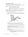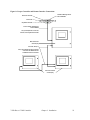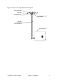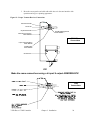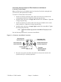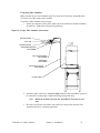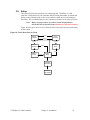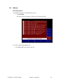
1
SCC 7-Pump 50D & D Plus-Station Controllers
Part Number: 882.00254.00
Bulletin Number: CV3-645
Effective: 11/27/05
Write Down Your Serial Numbers Here For Future Reference:
_________________________
_________________________
_________________________
_________________________
_________________________
_________________________
We are committed to a continuing program of product improvement.
Specifications, appearance, and dimensions described in this manual are subject to change without notice.
DCN No. ____________
© Copyright 2005
All rights reserved.
Please note that our address and phone information has changed.
Please reference this page for updated contact information.
These manuals are obsolete and are provided only for their technical information, data and capacities.
Portions of these manuals detailing procedures or precautions in the operation, inspection, maintenance
and repair of the products may be inadequate, inaccurate, and/or incomplete and shouldn’t be relied
upon. Please contact the ACS Group for more current information about these manuals and their
warnings and precautions.
Parts and Service Department
The ACS Customer Service Group will provide your company with genuine OEM quality parts manufactured to engineering
design specifications, which will maximize your equipment’s performance and efficiency. To assist in expediting your phone
or fax order, please have the model and serial number of your unit when you contact us. A customer replacement parts list
is included in this manual for your convenience. ACS welcomes inquiries on all your parts needs and is dedicated to
providing excellent customer service.
For immediate assistance, please contact:
•
North, Central and South America, 8am – 5pm CST +1 (800) 483-3919 for drying, conveying, heating and cooling
and automation. For size reduction: +1 (800) 229-2919.
North America, emergencies after 5pm CST (847) 439-5855
North America email: [email protected]
•
Mexico, Central & South America
Email: [email protected]
•
Europe, Middle East & Africa +48 22 390 9720
Email: [email protected]
•
India +91 21 35329112
Email: [email protected]
•
Asia/Australia +86 512 8717 1919
Email: [email protected]
Sales and Contracting Department
Our products are sold by a worldwide network of independent sales representatives. Contact our Sales Department for the
name of the sales representative nearest you.
Let us install your system. The Contract Department offers any or all of these services: project planning; system packages
including drawings; equipment, labor, and construction materials; and union or non-union installations.
For assistance with your sales or system contracting needs please Call:
North, Central and South America +1 (262) 641-8600 or +1 (847) 273-7700 Monday–Friday, 8am–5pm CST
Europe/Middle East/Africa +48 22 390 9720
India +91 21 35329112
Asia/Australia +86 512 8717 1919
Facilities:
ACS offers facilities around the world to service you no matter where you are located. For more information, please visit us at
www.acscorporate.com
United States:
ACS Schaumburg – Corporate Offices
1100 E. Woodfield Road
Suite 588
Schaumburg, IL 60173
Phone: + 1 847 273 7700
Fax: + 1 847 273 7804
ACS New Berlin – Manufacturing Facility
th
2900 S. 160 Street
New Berlin, WI 53151
Phone : +1 262 641 8600
Fax: + 1 262 641 8653
Asia/Australia:
ACS Suzhou
109 Xingpu Road SIP
Suzhou, China 215126
Phone: + 86 8717 1919
Fax: +86 512 8717 1916
Europe/Middle East/Africa:
ACS Warsaw
Ul. Działkowa 115
02-234 Warszawa
Phone: + 48 22 390 9720
Fax: +48 22 390 9724
India
ACS India
Gat No. 191/1, Sandbhor Complex
Mhalunge, Chakan, Tal Khed,
Dist. Pune 410501, India
Phone: +91 21 35329112
Fax: + 91 20 40147576
Shipping Information
Unpacking and Inspection
You should inspect your equipment for possible shipping damage. Thoroughly check the
equipment for any damage that might have occurred in transit, such as broken or loose wiring
and components, loose hardware and mounting screws, etc.
In the Event of Shipping Damage
According to the contract terms and conditions of the Carrier, the responsibility of the
Shipper ends at the time and place of shipment.
Notify the transportation company’s local agent if you discover damage
Hold the damaged goods and packing material for the examining agent’s inspection. Do not
return any goods before the transportation company’s inspection and authorization.
File a claim with the transportation company. Substantiate the claim by referring to the
agent’s report. A certified copy of our invoice is available upon request. The original Bill of
Lading is attached to our original invoice. If the shipment was prepaid, write us for a
receipted transportation bill.
Advise customer service regarding your wish for assistance and to obtain an RMA (return
material authorization) number.
If the Shipment is Not Complete
Check the packing list as back-ordered items are noted on the packing list. In addition to the
equipment itself, you should have:
;.. Bill of lading
;.. Packing list
;.. Operating and Installation packet
; Electrical schematic and panel layout drawings
;.. Component instruction manuals (if applicable)
Re-inspect the container and packing material to see if you missed any smaller items during
unpacking.
If the Shipment is Not Correct
If the shipment is not what you ordered, contact the shipping department immediately. For
shipments in the United States and Canada, call 1 (630) 595-1060; for all other countries, call
our international desk at (630) 595-1060. Have the order number and item number available.
Hold the items until you receive shipping instructions.
Returns
Do not return any damaged or incorrect items until you receive shipping instructions from the
shipping department.
7/50D Plus or 7/50D Controller
Chapter 1: Safety
2
Table of Contents
CHAPTER 1: SAFETY ................................................................ 6
1-1
1-2
1-3
How to Use This Manual ............................................................................................. 6
Safety Symbols Used in this Manual .....................................................................6
Warnings and Precautions .......................................................................................... 7
Responsibility .............................................................................................................. 8
General Responsibility...........................................................................................8
Operator Responsibility .........................................................................................9
Maintenance Responsibility...................................................................................9
Reporting a Safety Defect .....................................................................................9
CHAPTER 2: FUNCTIONAL DESCRIPTION............................ 10
2-1
2-2
2-3
2-4
2-5
Models Covered in This Manual................................................................................ 10
General Description................................................................................................... 10
Standard Features..................................................................................................... 11
Mechanical Features ...........................................................................................11
Electrical Features...............................................................................................11
Controller Features..............................................................................................11
Optional Features...................................................................................................... 12
Safety Devices and Interlocks ................................................................................... 12
Safety Circuit Standards......................................................................................12
Fail Safe Operation .............................................................................................12
Safety Device Lock-Outs .....................................................................................13
CHAPTER 3: INSTALLATION .................................................. 14
3-1
3-2
3-3
3-4
3-5
3-6
Uncrating ................................................................................................................... 14
Mounting the Control Panel....................................................................................... 14
System Installation Overview .................................................................................... 14
Electrical Connections............................................................................................... 15
Making Control Panel Power Drop Wiring Connections ......................................15
Running KwikLink™ Cables ................................................................................15
Setting Up and Installing Mounting Plates...........................................................17
Terminating Cable Runs......................................................................................18
Addressing and Installing ArmorBlocks™ ...........................................................20
Installing KwikLink™ Connectors ........................................................................23
Connecting the Controller to the Network............................................................24
Connecting the Power Supply Enclosure to the Network ....................................26
Connecting Vacuum Receivers to the Network ...................................................28
Connecting Vacuum Pumps and Filter Chambers to the Network ......................30
Connecting Central Alarms to the Network .........................................................33
Setup ......................................................................................................................... 35
Setting Up the System.........................................................................................36
Setting Up Stations..............................................................................................43
Setting Up Pumps ...............................................................................................47
Finishing Setup: Setting Up Passwords ..............................................................51
Initial Startup............................................................................................................... 53
7/50D Plus or 7/50D Controller
Chapter 1: Safety
3
CHAPTER 4: OPERATION ........................................................ 54
4-1
4-2
4-3
4-4
3-5
Overview ................................................................................................................... 54
Starting and Stopping the System............................................................................. 54
Basic Tasks ............................................................................................................... 55
Reviewing Station Status ....................................................................................55
Reviewing Pump Status ......................................................................................57
Logging On and Logging Off ...............................................................................59
Enabling and Disabling Stations and Pumps.......................................................60
Reviewing and Adjusting Basic Station Settings .................................................61
Advanced Tasks........................................................................................................ 64
Reviewing and Resetting a Pump Hour Meter ....................................................65
Transferring Stations to a Standby Pump............................................................66
Alarms ....................................................................................................................... 69
Reviewing Alarms................................................................................................69
Clearing the Alarm Log........................................................................................70
Silencing Alarms..................................................................................................71
CHAPTER 5: MAINTENANCE .................................................. 72
5-1
5-2
Preventative Maintenance......................................................................................... 72
Corrective Maintenance ............................................................................................ 72
Network Scanner Module Considerations ...........................................................72
CHAPTER 6: CONFIGURABLE SETTINGS............................. 73
6-1
6-2
6-3
Memory Module Considerations................................................................................ 73
Options for Station Setup .......................................................................................... 73
Options for Pump Setup ............................................................................................ 78
CHAPTER 7: TROUBLESHOOTING ........................................ 80
7-1
General Troubleshooting........................................................................................... 80
7-2 Alarms.......................................................................................................................... 81
Station Alarms .....................................................................................................81
Pump Alarms .......................................................................................................82
System Alarms ....................................................................................................83
CHAPTER 8: APPENDIX .......................................................... 84
8-1
8-2
8-3
8-4
8-5
Warranty.................................................................................................................... 84
Warranty Specifications.........................................Error! Bookmark not defined.
Warranty Restrictions ............................................Error! Bookmark not defined.
Warranty Liabilities ................................................Error! Bookmark not defined.
Customer Responsibilities .....................................Error! Bookmark not defined.
Optional Components................................................................................................ 84
Drawings and Diagrams ............................................................................................ 85
Spare Parts List......................................................................................................... 88
AC Voltage ..........................................................................................................88
DC Voltage ..........................................................................................................88
Returned Material Policy ........................................................................................... 88
Credit Returns .....................................................................................................88
Warranty Returns ................................................................................................89
7/50D Plus or 7/50D Controller
Chapter 1: Safety
4
8-6
8-7
8-8
Safety Tag Information .............................................................................................. 89
Controller Safety Tags.........................................................................................89
Controller Identification (Serial Number) Tag ............................................................ 89
Technical Assistance (Contact Information).............................................................. 90
Parts Department ................................................................................................90
Service Department.............................................................................................90
Sales Department................................................................................................90
Contract Department ...........................................................................................90
7/50D Plus or 7/50D Controller
Chapter 1: Safety
5
Chapter 1: Safety
1-1
How to Use This Manual
Use this manual as a guide and reference for installing, operating, and maintaining your
equipment. The purpose is to assist you in applying efficient, proven techniques that enhance
equipment productivity.
This manual covers only light corrective maintenance. No other maintenance should be
undertaken without first contacting a service engineer.
The Functional Description section outlines models covered, standard features, and optional
features. Additional sections within the manual provide instructions for installation, preoperational procedures, operation, preventive maintenance, and corrective maintenance.
The Installation chapter includes required data for receiving, unpacking, inspecting, and setup
of the equipment. We can also provide the assistance of a factory-trained technician to help
train your operator(s) for a nominal charge. This section includes instructions, checks, and
adjustments that should be followed before commencing with operation of the equipment.
These instructions are intended to supplement standard shop procedures performed at shift,
daily, and weekly intervals.
The Operation chapter includes a description of electrical and mechanical controls, in
addition to information for operating the equipment safely and efficiently.
The Maintenance chapter is intended to serve as a source of detailed assembly and
disassembly instructions for those areas of the equipment requiring service. Preventive
maintenance sections are included to ensure that your equipment provides excellent, long
service.
The Troubleshooting chapter serves as a guide for identification of most common problems.
Potential problems are listed, along with possible causes and related solutions.
The Appendix contains technical specifications, drawings, schematics, and parts lists. A
spare parts list with part numbers specific to your machine is provided with your shipping
paperwork package. Refer to this section for a listing of spare parts for purchase. Have your
serial number and model number ready when ordering.
Safety Symbols Used in this Manual
The following safety alert symbols are used to alert you to potential personal injury hazards.
Obey all safety messages that follow these symbols to avoid possible injury or death.
Danger!
DANGER indicates an imminently hazardous situation which, if not
avoided, will result in death or serious injury.
Warning!
WARNING indicates a potentially hazardous situation or practice which,
if not avoided, could result in death or serious injury.
Caution!
CAUTION indicates a potentially hazardous situation or practice which, if
not avoided, may result in minor or moderate injury or in property
damage.
7/50D Plus or 7/50D Controller
Chapter 1: Safety
6
1-2
Warnings and Precautions
Our equipment is designed to provide safe and reliable operation when installed and operated
within design specifications, following national and local safety codes. This may include, but
is not limited to OSHA, NEC, CSA, SPI, and any other local, national and international
regulations.
To avoid possible personal injury or equipment damage when installing, operating, or
maintaining this equipment, use good judgment and follow these safe practices:
; Read and follow these operation and installation instructions when installing,
operating, and maintaining this equipment. If these instructions become
damaged or unreadable, additional copies are available from the manufacturer.
; Follow all SAFETY CODES.
; Wear SAFETY GLASSES and WORK GLOVES.
; Work only with approved tools and devices.
; Disconnect and/or lock out power before servicing or maintaining the equipment.
; Use care when LOADING, UNLOADING, RIGGING, or MOVING this
equipment.
; Operate this equipment within design specifications.
; OPEN, TAG, and LOCK ALL DISCONNECTS before working on equipment.
You should remove the fuses and carry them with you.
; Make sure the equipment and components are properly GROUNDED before you
switch on power.
; Use extreme caution when working with your conveying system. HIGH VACUUM
can be dangerous. Keep body parts, tools, clothing, and debris away from vacuum
inlets.
; When welding or brazing in or around this equipment, make sure VENTILATION is
ADEQUATE. PROTECT adjacent materials from flame or sparks by shielding with
sheet metal. An approved FIRE EXTINGUISHER should be close at hand and
ready for use if needed.
; Do not restore power until you remove all tools, test equipment, etc., and the
equipment and related components are fully reassembled.
; Only PROPERLY TRAINED personnel familiar with the information in this
manual should work on this equipment.
We have long recognized the importance of safety and have designed and manufactured our
equipment with operator safety as a prime consideration. We expect you, as a user, to abide
by the foregoing recommendations in order to make operator safety a reality.
7/50D Plus or 7/50D Controller
Chapter 1: Safety
7
1-3
Responsibility
These machines are constructed for maximum operator safety when used under standard
operating conditions and when recommended instructions are followed in the maintenance
and operation of the machine.
All personnel engaged in the use of the machine should become familiar with its operation as
described in this manual.
Proper operation of the machine promotes safety for the operator and all workers in its
vicinity.
Each individual must take responsibility for observing the prescribed safety rules as outlined.
All warning and danger signs must be observed and obeyed. All actual or potential danger
areas must be reported to your immediate supervisor.
General Responsibility
No mater who you are, safety is important. Owners, operators and maintenance personnel
must realize that every day, safety is a vital part of their jobs.
If your main concern is loss of productivity, remember that production is always affected in a
negative way following an accident. The following are some of the ways that accidents can
affect your production:
• Loss of a skilled operator (temporarily or permanently)
• Breakdown of shop morale
• Costly damage to equipment
• Downtime
An effective safety program is responsible and economically sound.
Organize a safety committee or group, and hold regular meetings. Promote this group from
the management level. Through this group, the safety program can be continually reviewed,
maintained, and improved. Keep minutes or a record of the meetings.
Hold daily equipment inspections in addition to regular maintenance checks. You will keep
your equipment safe for production and exhibit your commitment to safety.
Please read and use this manual as a guide to equipment safety. This manual contains safety
warnings throughout, specific to each function and point of operation.
7/50D Plus or 7/50D Controller
Chapter 1: Safety
8
Operator Responsibility
The operator’s responsibility does not end with efficient production. The operator usually has
the most daily contact with the equipment and intimately knows its capabilities and
limitations.
Plant and personnel safety is sometimes forgotten in the desire to meet incentive rates, or
through a casual attitude toward machinery formed over a period of months or years. Your
employer probably has established a set of safety rules in your workplace. Those rules, this
manual, or any other safety information will not keep you from being injured while operating
your equipment.
Learn and always use safe operation. Cooperate with co-workers to promote safe practices.
Immediately report any potentially dangerous situation to your supervisor or appropriate
person.
Maintenance Responsibility
Proper maintenance is essential to safety. If you are a maintenance worker, you must make
safety a priority to effectively repair and maintain equipment.
Before removing, adjusting, or replacing parts on a machine, remember to turn off all electric
supplies and all accessory equipment at the machine, and disconnect and lockout electrical
power. Attach warning tags to the disconnect switch.
Be sure that all non-current carrying parts are correctly connected to earth ground with an
electrical conductor that complies with current codes. Install in accordance with national and
local codes.
When you have completed the repair or maintenance procedure, check your work, remove
your tools. Rigging, and handling equipment.
Reporting a Safety Defect
If you believe that your equipment has a defect that could cause injury, you should
immediately discontinue its use and inform the manufacturer.
The principle factors that can result in injury are failure to follow proper operating procedures
(i.e. lockout/tagout), or failure to maintain a clean and safe working environment.
7/50D Plus or 7/50D Controller
Chapter 1: Safety
9
Chapter 2: Functional Description
2-1
Models Covered in This Manual
This manual provides operation, installation, and maintenance instructions for 7-Pump, 50D
& D Plus-Station Conveying Controllers. Model numbers are listed on the serial tag. Make
sure you know the model and serial number of your equipment before contacting the
manufacturer for parts or service.
The 7-Pump, 50D & D Plus-Station Conveying Controller is a programmable logic
controller, with 24 VDC or 115 VAC control circuit, easy-to-use touchscreen operator
interface terminal and optional audible/visual alarm.
2-2
General Description
Our material conveying systems create vacuum for the automatic conveying of most freeflowing, dry, pelletized, or granular materials. Material characteristics determine the type of
equipment needed to convey the material.
A typical use for our equipment is an in-plant distribution system for plastic processing
plants.
Our central vacuum systems are as varied as the applications they service. The tubing and
equipment furnished in our system is designed to convey the material(s) specified at the time
of purchase at specific rates and distances.
We can advise you on your system capabilities based on system makeup, distance, material,
and conveying rates you want.
System capacity is directly affected by the pressure drop in the overall system, such as
number of material line bends, pipe length, Y-tubes, T-tubes, etc.
Use the minimum effective amount of vinyl flex hose to maximize material line efficiency.
Keep material lines as straight as possible. Refer to the Mechanical Components Product
manual (Part No. A0536580) for installation recommendations.
Note:
7/50D Plus or 7/50D Controller
Vacuum leaks occurring anywhere in your system reduce capacity.
Chapter 2: Functional Description
10
2-3
Standard Features
Mechanical Features
Time-fill Capability. The length of time allowed for material to drain from the station to its
receiver. During this time, the controller does not attempt to deliver any more material to the
station.
Volume-fill Capability. The length of time a station’s vacuum valve remains open to allow
material to be drawn in. The vacuum valve will close when material covers the station’s
volume-fill proximity sensor or this time elapses, whichever comes first.
Vent Valve Output. The vent valve protects the pump motor from damage during high
vacuum conditions if an undetected failure of the vacuum switch should occur. The vent
valve limits system vacuum by allowing a plunger in the valve to shift and vent the pump.
Closed-Loop Conveying. This feature allows material to be conveyed and processed
without being contaminated by outside influences (such as dust, other materials, etc.).
Common Purge Valve Output Control for Each Pump. This feature allows any remaining
material to be cleaned out of the vacuum pump or station.
Local Blowback Filter Cleaning Outputs. When this feature is enabled, the controller
periodically sends compressed air backward through the pump’s air filter to dislodge
accumulated dust and debris.
Electrical Features
• 115/1/60 or 230/1/50/60 supply voltage
• 24 VDC control voltage
• Single-point power and ground connection
• Non-fused disconnect switch, lockable
• Branch circuit fusing
• Fully accessible NEMA 4-style electrical control enclosure
Controller Features
• Allen-Bradley SLC 5/04 programmable controller with 10” color touch screen operator
interface
• Diagnostics, operating instructions and parts information are built into the interface
• Controls up to fifty (50) stations and up to seven (7) Vacuum Power Units.
• Controls up to three central alarms
• Allows operator to transfer stations to a standby pump when a pump fails
• Electronic time delay between pump startups to prevent an excessive power demand at
your facility
7/50D Plus or 7/50D Controller
Chapter 2: Functional Description
11
2-4
Optional Features
Options marked with “*” indicate options that can be factory installed or retrofitted in the
field.
230/1/60 Operation. Required to operate with a 230/1/60 supply voltage.
Additional audible/visual alarm with silence button. Alarm light and horn assembly that
can be remote mounted and wired into the controller to indicate an alarm condition.
Remote Interface.
Central Purge Capability.
Material Line Proofing – includes an additional PLC located near the quick change
manifold.
CE Package for 220/1/50 Operation. Required in Europe and other areas that need
220/1/50 supply voltage.
2-5
Safety Devices and Interlocks
This section includes information on safety devices and procedures that are inherent to the
Controller. This manual is not intended to supersede or alter safety standards established by
the user of this equipment. Instead, the material contained in this section is recommended to
supplement these procedures in order to provide a safer working environment.
At the completion of this section, the operator and maintenance personnel will be able to do
the following:
•
Identify and locate specific safety devices.
•
Understand the proper use of the safety devices provided.
•
Describe the function of the safety device.
Safety Circuit Standards
Safety circuits used in industrial systems protect the operator and maintenance personnel
from dangerous energy. They also provide a means of locking out or isolating the energy for
servicing equipment.
Various agencies have contributed to the establishment of safety standards that apply to the
design and manufacture of automated equipment. The Occupational Safety and Health
Administration (OSHA) and the Joint Industrial council (JIC) are just a few of the
organizations that have joined with the plastics industry to develop safety standards.
Every effort has been made to incorporate these standards into the design of the controller;
however, it is the responsibility of the personnel operating and maintaining the equipment to
familiarize themselves with the safety procedures and the proper use of any safety devices.
Fail Safe Operation
If a safety device or circuit should fail, the design must be such that the failure causes a
“Safe” condition. As an example, a safety switch must be a normally open switch. The switch
must be held closed with the device it is to protect. If the switch fails, it will go to the open
condition, tripping out the safety circuit.
7/50D Plus or 7/50D Controller
Chapter 2: Functional Description
12
At no time should the safety device fail and allow the operation to continue for example, if a
safety switch is guarding a motor, and the safety switch fails, the motor should not be able to
run.
Safety Device Lock-Outs
Some safety devices disconnect electrical energy from a circuit. The safety devices that are
used in this Controller are primarily concerned with electrical power disconnection.
WARNING!
Always disconnect and lockout all electrical power and pneumatic (i.e. compressed air)
sources prior to servicing the 7-Pump, 50D & D Plus-Station Controller. Failure to
do so may result in serious injury. No one but the person who installed the lockout
may remove it.
7/50D Plus or 7/50D Controller
Chapter 2: Functional Description
13
Chapter 3: Installation
3-1
Uncrating
7-Pump, 50D & D Plus-Station Controllers are shipped mounted on a skid, enclosed in a
plastic wrapper, and contained in a cardboard box.
1. Pry the crating away from the skid.
Note:
Remove the nails holding the box to the skid and lift the box off
carefully; avoiding staples in the 1’ x 4’ wood supports. Cut the steel
banding.
2. Use a pry bar to remove the blocks securing the unit to the skid.
3. Lift unit from sides, inserting forklift under the base. The forks must be equidistant
from the centerline of the unit and the unit must be balanced on the forks. Lift
slowly and only high enough to clear the skid. Use a pry bar if necessary to
carefully remove the skid from the unit.
4. Lower slowly.
3-2
Mounting the Control Panel
Note:
Before you mount the panel, consider how you run wiring to the
KwikLink connectors, ArmorBlocks, vacuum hoppers, the filter chamber atmospheric valve (if so equipped) and the pump motor starter(s),
vacuum switch(es), and vent valve(s).
Mount the control panel on a flat, vertical area. It should be a visible area that gives your
operator access to the control. The panel requires a low voltage power drop as listed on the
serial tag.
3-3
System Installation Overview
Installing the 7-pump 50-station controller is easy and straightforward. Because the system
uses networked distributed I/O modules, you’ll only need to run two cables for the entire
system.
The following is a typical installation sequence:
1. Run the black power and the grey data KwikLink™ flat cables from the start of the
system to the end, attaching them to vacuum tubing with nylon cable ties.
2. Set up mounting plates with tubing clamps; install KwikLink™ connectors and
ArmorBlocks onto mounting plates as required.
3. Install KwikLink connectors and ArmorBlock™ cable plates to mounting plates, and
install on vacuum tubing at each node location, just before a T-fitting or valve.
4. Install cable terminations.
5. Determine location of network system nodes, and set addresses for ArmorBlocks as
required.
6. Set up and connect to the controller and, if purchased, remote display. Connect grey
patch cords from controller terminals to KwikLink connectors installed in Step 3.
7/50D Plus or 7/50D Controller
Chapter 3: Installation
14
7. After determining quantity and location(s) of where to install system power
supply(ies) (consult factory); set up and connect to KwikLink connectors installed in
Step 3.
8. Set up and connect vacuum receiver stations to ArmorBlocks installed in Step 3,
using yellow patch cords.
9. Set up and connect vacuum pump stations and filter chambers to ArmorBlocks
installed in Step 3, using yellow patch cords.
10. Determine location(s) of central alarm(s); set up and connect alarms using yellow
patch cords.
The following sections provide detailed information on these installation steps.
3-4
Electrical Connections
Refer to local electrical codes, the schematic and connection diagrams supplied with this unit
and the serial tag for wiring considerations. Run all wiring in conduit if codes require it.
Making Control Panel Power Drop Wiring Connections
Hardwire the input power at 115/1/50-60 VAC or 230/1/50-60 VAC, depending on the
specifications, which are located on the Control Panel Serial Tag. The control enclosure
draws less than five (5) amps during normal operation at 115/1/50-60 VAC. The main power
switch is located on the right side of the enclosure.
Caution!
We recommend that you protect PLC memory by providing the control
panel with a dedicated circuit, a true earth ground, and a spike/surge
protector.
Running KwikLink™ Cables
About KwikLink Flat Cables
KwikLink flat cable is physically keyed to prevent wiring mishaps. This type of cable is
unshielded and contains four conductors. Use a long-jawed straight-bladed cable cutter at
least 1½” long to cut KwikLink flat cable.
You’ll install two (2) colors of flat cable: black and grey. The black cable transmits output
power, and the grey cable transmits input power and data transmission.
Figure 1: KwikLink Cable Cross-Section, Edge Identification
Cross Section
7/50D Plus or 7/50D Controller
Edge Identification
Chapter 3: Installation
15
Installing KwikLink Cable
Before you install flat cable, determine how much length you need to install black power
cable and grey data cable. Typical installations have equal lengths of each. This is a good
time to plan for the future, and run these cables to each possible location in the plant. Use a
straight-blade cable cutter to make the cut at each end.
To install KwikLink cables:
1. Cut both black and grey cables to the proper length.
2. Use cable ties to attach KwikLink cables, black cable above grey cable, on the
vacuum tubing. Attach cable to the tubing with cable ties at about three-foot (3 ft./
1 m) invervals. Make sure that cable ties are snug, but not tightened enough to bend
the flat cable.
Caution!
Install KwikLink cable on vacuum tubing only. DO NOT install KwikLink
cable on material conveying tubing, as static electricity formed at material
lines could disrupt system operation.
Figure 2: Side View of a Typical Power Cable and Data Cable Installation
Cable tie, buckle
Vacuum tube
Black power cable
Grey data cable
Note:
7/50D Plus or 7/50D Controller
When approaching a node location, stop the attachment process. Run
the cables over the node area (such as a T-valve) and make sure you
create a slight amount of slack when continuing the attachment with
cable ties. Doing so lets you install KwikLink connectors or
ArmorBlocks with greater ease, with less stress on the cable.
Chapter 3: Installation
16
Setting Up and Installing Mounting Plates
Setting Up Mounting Plates
It’s a good idea to get all your mounting plates set up with KwikLink connector bases or
ArmorBlock cable bases before installation, as your system layout determines.
Note:
ArmorBlock cable bases are installed on mounting plates
perpendicular in orientation to the flat cable runs.
Vacuum hoppers/receiver stations require 8-connector ArmorBlocks; vacuum
pumps and central alarm stations require 4-connector ArmorBlocks.
Make sure that each mounting plate has properly attached tube clamps as required. Each
mounting plate requires two (2) tube clamps. Always use locking washers, especially in
high-vibration environments.
Figure 3: Side View of a Typical Mounting Plate Assembly with ArmorBlock Base
Rotate 30º to 45º downward
Installing Assembled Mounting Plates
After you’ve set up the mounting plates:
1. Install them at each node location by clipping the tubing clamps onto the vacuum
tube, just before the node area (such as a T-valve).
2. Orient the mounting plate parallel with the flat cables and at a 30º to 45º angle so the
KwikLink connector or ArmorBlock faces the operator on the floor; torque the tubing
clamp fasteners until tight.
The flat cable will be installed inside KwikLink connectors and ArmorBlocks as described in
the following sections of this chapter.
7/50D Plus or 7/50D Controller
Chapter 3: Installation
17
Terminating Cable Runs
After you’ve run the black and grey network cables, you need to properly terminate the ends
of the cables. By doing so, you’ll insure that the network runs properly. You will also have
the benefit of being able to measure voltage in the system without disrupting operation.
This section lists procedures for terminating these cables. To properly terminate a cable run:
1. Mount three standard KwikLink connectors to a mounting plate in a triangle
configuration. See Figure 4 on Page 19 for an illustration.
Make sure that each connector is installed with the hinge side down.
2. Mount the tubing clamps to the mounting plates. Each mounting plate requires two
(2) tubing clamps.
3. Mount the standard resistor cap from the KwikLink connector kit on the top center
KwikLink connector for the black power flat cable. The standard resistor cap has
metal prongs in the center.
Repeat for the outside end KwikLink connector on the grey data flat cable.
4. For the inside KwikLink connector (next to the outside end on the grey cable), mount
a separately-packaged blank cap on it instead of the standard resistor cap in the
KwikLink connector kit.
Discard the standard resistor cap to eliminate confusion.
5. Mount the mounting plate assembly on the vacuum line at the end of the cable run.
See Page 17 for more information.
6. Using the straight-blade cable cutter, carefully trim each flat cable so it sticks out past
the final KwikLink connector by 1/4” to 3/8”.
Place a dust cap over the end of the trimmed cable.
7. Lay the dust cap and cable into the KwikLink connector so the dust cap tabs engage
in the connector slots. The dust cap tabs should fit into the connector slots perfectly.
Left
Right
8. Lay the cable in the hinged base, noting the correct keyed profile; flat edge toward
the hinge, keyed edge toward the latch. Make sure that the cable and dust cap are
properly seated inside.
9. Making sure that the cable is completely straight, carefully close the hinged
assembly, and apply firm, even pressure until the first latch locks into place.
Note:
Make sure that the flat cable is completely staight before continuing!!
The latch has two catches; the first loosely holds the connector on the cable, the
second requires more pressure to close the connector tightly. The cable must be in the
correct position for the connector to close properly.
7/50D Plus or 7/50D Controller
Chapter 3: Installation
18
10. Drive the two screws at the center points about halfway down; first on the latch side,
then the hinge side.
11. Continue to tighten the screws a little at a time until fully tightened; no more than 15
inch-pounds (5.6 N•m) of torque.
Note:
You can only pierce the cable once. Once pierced, the KwikLock
connector must not be removed. This insures that the inner conductors
are not exposed to the elements.
Installing Inside KwikLink Connectors with Blank Caps
Once installed on the grey data cables, these connectors permit you to measure voltage in the
system so you can analyze how it is working. The system cannot work properly unless these
inside-mounted connectors have the blank (non-conductor) caps installed.
1. Lay the cable in the hinged base, noting the correct keyed profile; flat edge toward
the hinge, keyed edge toward the latch. Make sure that the cable is properly seated
inside.
2. Making sure that the cable is completely straight, carefully close the hinged
assembly, and apply firm, even pressure until the first latch locks into place.
Note:
Make sure that the flat cable is completely straight before continuing!!
The latch has two catches; the first loosely holds the connector on the cable, the
second requires more pressure to close the connector tightly. The cable must be in the
correct position for the connector to close properly.
3. Drive the two screws at the center points about halfway down; first on the latch side,
then the hinge side.
4. Continue to tighten the screws a little at a time until fully tightened; no more than 15
inch-pounds (5.6 N•m) of torque.
Note:
You can only pierce the cable once. Once pierced, the KwikLock
connector must not be removed. This insures that the inner conductors
are not exposed to the elements.
The system should now be properly terminated. You can now continue to install components
on the system.
Figure 4: Proper Termination Connections
Standard KwikLink
Connectors
Dust Caps
KwikLink
Connector
Inside Inside
KwikLink
Connector
with Blank Cap
with Blank Cap
Inside KwikLink
Connector
Inside
KwikLink
Connector
with Blank
with
BlankCapCap
ArmorBlock Mounting Plate Kit
ArmorBlock Mounting Plate Kit
Part
AEC PNo.
t NA0556696
A0556696
7/50D Plus or 7/50D Controller
Chapter 3: Installation
19
Addressing and Installing ArmorBlocks™
Addressing Armorblocks
An ArmorBlock permits you to give it a number “address” so that the controller network
system can recognize its location and function. ArmorBlocks are used at vacuum
hopper/receiver, pump, and alarm node locations.
ArmorBlock Address Ranges
The number range of ArmorBlock addresses are as follows:
• 01 to 50 — Vacuum hopper/receiver stations; use a leading zero for
numbers 01 to 09.
• 51 to 57 — Pump stations
• 58 to 60 — Alarm stations
Setting Armorblock Addresses
Locate the rotary switches underneath the ArmorBlock. The two switches are:
• MSD (most significant digit) for tens
• LSD (least significant digit) for units/ones
For example, if you wanted to set an address at 36, you set the MSD rotary switch at 3 and
the LSD rotary switch at 6. To set an address of 8, set the MSD rotary switch at 0 (leading
zero), then set the LSD rotary switch at 8.
• Using a permanent black marker, write the number of the address
on the white label located on the bottom front of the ArmorBlock.
We suggest that you place numbered tags at node locations to ease
installation and reduce any confusion of locations.
To set the node address:
• Use a small straight-bladed screwdriver to rotate the switches.
Line up the small arrowhead on the switch with the number you want
to select.
The following figure shows that the address is set at 01; the MSD rotary switch is set at 0 and
the LSD rotary switch is set at 1.
Figure 5: ArmorBlock Address Node Rotary Switches
7/50D Plus or 7/50D Controller
Chapter 3: Installation
20
Installing ArmorBlocks
The ArmorBlock cable base should already be attached to the mounting plate, aligned so it is
perpendicular to the flat cables. If not, reinstall it with its proper alignment.
To install the flat cables in the ArmorBlock cable base:
1. Lay the flat cable into the ArmorBlock cable base, grey data cable on the bottom and
the black power cable on the top, making sure that the keyed edge is properly seated
toward the top.
Caution!
EXERCISE CARE when handling the seal block.
Cable contacts are SHARP!
Only ONE attempt to pierce the cable is allowed for proper contact.
Figure 6: Using seal block to pierce cable
2. Align the seal block so the L-shaped tabs are towards the top, and the arrows are
matched on the bottom of the cable base and seal block. Make sure that the arrows
and the four captive screws on the seal block are properly aligned. Gently press it
into place.
Make sure that you align the seal block properly when you attach it to the base.
Doing so maintains the integrity of the sealed base.
Note:
7/50D Plus or 7/50D Controller
You can only pierce the cable once. Once pierced, the seal block must
not be removed. This insures that the inner conductors are not exposed
to the elements.
Chapter 3: Installation
21
Figure 7: Securing the Seal Block to the Cable Base
To secure the seal block:
1. Start the threads of each of the four captive screws into the cable base receptacle
holes.
2. Drive each of the screws about halfway down, using the proper torque sequence:
Bottom screw, top screw, left screw, right screw. Doing so insures that the cables are
pierced evenly.
3. Using the proper torque sequence, tighten each screw, a little at a time, until the
seal block is fully seated into the cable base. Tighten to no more than 8 to 10 inchpounds (3.0 to 3.7 N•m) of torque.
The three seat lines on the seal block should meet the cable base, indicating that the
seal block is fully seated. The seal block clips should also click into place onto the
corresponding cable base slots.
7/50D Plus or 7/50D Controller
Chapter 3: Installation
22
Installing KwikLink™ Connectors
KwikLink connectors let you connect the controller and the power supply to the system. They
are also used to electronically terminate power cable and data cable runs.
Just like ArmorBlocks, KwikLink connectors are insulation displacement connectors (IDCs).
Caution!
Exercise care when installing Kwiklink connectors.
IDC blades on KwikLink connectors are SHARP!
Gently push back any protruding IDC blades before installing flat cables
inside.
The KwikLink connector should already be attached to the mounting plate, so the hinge side
is down. If not, reinstall it with its proper alignment, along the correct flat cable. See the
installation drawing located in your Customer Information Packet for further details.
To install flat cable inside KwikLink connectors:
1. Lay the cable in the hinged base, noting the correct keyed profile; flat edge toward
the hinge, keyed edge toward the latch. Make sure that the cable is properly seated
inside.
2. Making sure that the cable is completely straight, carefully close the hinged
assembly, and apply firm, even pressure until the first latch locks into place.
Note:
Make sure that the flat cable is completely straight before continuing!
The latch has two catches; the first loosely holds the connector on the cable, the
second requires more pressure to close the connector tightly. The cable must be in the
correct position for the connector to close properly.
3. Drive the two screws at the center points about halfway down; first on the latch side,
then the hinge side.
4. Continue to tighten the screws a little at a time until fully tightened; no more than 15
inch-pounds (5.6 N•m) of torque.
Note:
7/50D Plus or 7/50D Controller
You can only pierce the cable once. Once pierced, the KwikLink
connector must not be removed. This insures that the inner conductors
are not exposed to the elements.
Chapter 3: Installation
23
Connecting the Controller to the Network
To connect the controller to the network, make sure that the KwikLink connector is properly
installed on the flat grey data cable. To connect:
1. Attach the keyed round connector to the terminal of the controller marked
NETWORK NO. 1. Tighten the cord grip ring until snug.
2. Align the square connector of the grey drop cable so the cable leads down from the
connector. Evenly press the square connector onto the top of the KwikLink
connector. It should make two audible snaps when properly seated.
3. Dress the excess cable with cable ties so it does not interfere with operation and gives
a pleasing appearance.
Connecting the Remote Interface to the Main Controller
After selecting a location and installing the remote interface, connect it to the main controller:
1. Determine the length of blue remote cable you need, and cut it to length.
2. Run the cable from the remote interface to the main controller, neatly dressing the
cable with cable ties so it does not interfere with system operation and to give it a
neat appearance.
3. Attach connectors at each end, following the connector manufacturer’s instructions.
4. Attach one connector to the remote interface terminal marked REMOTE DISPLAY.
Tighten the cord grip ring until snug.
5. Attach the other connector to the terminal of the controller marked REMOTE
DISPLAY. Tighten the cord grip ring until snug.
7/50D Plus or 7/50D Controller
Chapter 3: Installation
24
Figure 8: Proper Controller and Remote Interface Connections
ArmorBlock Mounting Plate Kit
Part No. A0556696
Black Power Flat Cable
Vacuum Tube
Grey Network Flat Cable
Power or Network Tap/Cable Drop
Part No. A0555195
One (1) Cord Required & is Connected,
as Shown, to the Grey Network Flat Cable
Main Touch-Screen
Control Display
Blue Cable, 20 ft. (6 m)
One (1) Cord is Needed per Display, as Shown
Connected to the Marked Terminals
of the Main & Remote Control Boxes
Remote Touch-Screen
Control Display
7/50D Plus or 7/50D Controller
Chapter 3: Installation
25
Connecting the Power Supply Enclosure to the Network
The power supply provides electrical power to make the system work. Some network layouts
require more than one power supply.
Location is also an important consideration when locating power supply enclosures on your
network. Contact the factory for determining how many power supply enclosures your system
needs, as well as where they need to be installed.
After you’ve mounted the power supply enclosure(s), you can connect them to your network.
To connect a power supply to the network:
1. Attach a KwikLink connector included in the bag with power cables to the flat
cables. One connector is used for the network grey cable and one connector is used
for the auxiliary power black cable.
2. Align the square connector of the grey drop cable so the cable leads down from the
connector. Evenly press the square connector onto the top of the bottom KwikLink
connector. It should make two audible snaps when properly seated.
3. Align the square connector of the black drop cable so the cable leads down from the
connector. Evenly press the square connector onto the top of the upper KwikLink
connector. It should make two separate, audible snaps when properly seated.
4. Attach the keyed round connectors to the receptacles on the side of the power supply
enclosure marked 24 VDC POWER SUPPLY. Tighten the cord grip ring until
snug.
5. Dress the excess cables with cable ties so they do not interfere with operation and to
give a pleasing appearance.
If more than one power supply is required to properly energize the grey network flat cable:
1. Remove the terminal block jumpers on all but the most centrally-located network
power supply enclosures.
For locations of jumpers, refer to the drawing shipped inside the power supply
enclosure
Note:
7/50D Plus or 7/50D Controller
Only one power supply should be connected to each section of the
black auxiliary power flat cable. Do not remove any jumpers on power
supplies that transmit energy to the black flat power cable.
Chapter 3: Installation
26
Figure 9: Proper Power Supply Enclosure Connections
Black Power Flat Cable
Vacuum Tube
Grey Network Flat Cable
ArmorBlock Mounting Plate Kit
Part No. A0556696
Power Cable
Part No. A0555195
Two (2) Cords Required
Power Supply Enclosure
7/50D Plus or 7/50D Controller
Chapter 3: Installation
27
Connecting Vacuum Receivers to the Network
Make sure that all previous installation steps have been done first before starting this task.
To connect a vacuum receiver to the network:
1. Attach one connector of the yellow patch cord to the terminal on the vacuum receiver
terminal box. Tighten the cord grip ring until snug.
2. Attach the other connector to the upper left terminal of the ArmorBlock. Tighten the
cord grip ring until snug.
Note:
Retain the terminal caps from the ArmorBlock. They may be used
later.
*** The installation steps listed above also apply to the 7/50D 4-connector
ArmorBlock.
Note the following illustrations for 4 and 8-connector ArmorBlocks:
Figure 10: 7/50D 4-Connector ArmorBlock Connections
Pump Verify (A-I0)
High Vacuum (A-I1)
Pump Starter (C-O0)
Vent Solenoid (C-O1)
Pump Fault #1 (B-I2)
Pump Fault #2 (B-I3)
Blowback Solenoid (D-O2)
Local Alarm Light (D-O3)
4 Input / 4 Output
ArmorBlock
T-Connector
AB#1485P-P1R4-DR4
Part No. A0555169
3. Dress the excess patch cord cable with cable ties so it does not interfere with
operation and gives a pleasing appearance.
Figure 11: 7/50D Plus 8-Connector ArmorBlock Connections
T-Connector
AB#1485P-P1R4-DR4
Part No. A0555169
Demand Switch (A-I0)
Volume Fill Prox. (A-I1)
Bypass Switch (B-I2)
Receiver Level
Sensor (C-I4)
Not used
Sequence Valve (E-O0)
Local Alarm Light (E-O1)
RPV Material 'A' Solenoid (F-O2)
RPV Material 'B' Solenoid (F-O3)
Slide Gate (G-O4)
Blowback (G-O5)
Purge Solenoid (H-O6)
8 Input / 8 Output
ArmorBlock
7/50D Plus or 7/50D Controller
Chapter 3: Installation
28
3. Dress the excess patch cord cable with cable ties so it does not interfere with
operation and to give a pleasing appearance.
Figure 12: Proper Vacuum Receiver Connections
Black Power Flat Cable
Vacuum Tube
Grey Network Flat Cable
ArmorBlock Mounting Plate Kit
Part No. A0556696
Yellow Patch Cord, 20 ft. (6 m)
Part No. A0555190
7/50 D Plus
Connections
8 Input / 8 Output ArmorBlock
Part No. A0555192
ArmorBlock Base
Part No. A0555191
Vacuum Receiver
OR
Make the same connections using a 4 input/ 4 output ARMORBLOCK
7/50D
Connections
7/50D Plus or 7/50D Controller
Chapter 3: Installation
29
Connecting Vacuum Pumps and Filter Chambers to the Network
Connecting Vacuum Pumps
Make sure that all previous installation steps have been done first before starting this task.
You’ll use two yellow patch cords to connect.
To connect a vacuum pump to the network:
1. Attach one connector of the first yellow patch cord to the lower terminal on the
vacuum pump terminal box. Tighten the cord grip ring until snug.
2. Attach the other connector to the upper left terminal of the ArmorBlock. Tighten the
cord grip ring until snug.
3. Attach one connector of a yellow patch cord to the upper terminal on the vacuum
pump terminal box. Tighten the cord grip ring until snug.
4. Attach the other connector to the upper right terminal of the ArmorBlock. Tighten
the cord grip ring until snug.
Note:
Retain the terminal caps from the ArmorBlock. They may be used
later.
Note the following illustration for 4-connector ArmorBlocks:
Figure 13: 4-Connector ArmorBlock Connections
Pump Verify (A-I0)
High Vacuum (A-I1)
Pump Fault #1 (B-I2)
Pump Fault #2 (B-I3)
4 Input / 4 Output
ArmorBlock
Pump Starter (C-O0)
Vent Solenoid (C-O1)
Blowback Solenoid (D-O2)
Local Alarm Light (D-O3)
T-Connector
AB#1485P-P1R4-DR4
Part No. A0555169
5. Dress the excess patch cord cables with cable ties so they do not interfere with
operation and to give a pleasing appearance.
7/50D Plus or 7/50D Controller
Chapter 3: Installation
30
Figure 14: Proper Vacuum Pump Connections
Black Power Flat Cable
Vacuum Tube
Grey Network Flat Cable
Yellow Patch Cord, 20 ft. (6 m)
Part No. A0555190
Two (2) Cords Required
ArmorBlock Mounting Plate Kit
Part No. A0556696
4 Input / 4 Output ArmorBlock
Part No. A0558296
ArmorBlock Base
Part No. A0555191
Vacuum Pump
7/50D Plus or 7/50D Controller
Chapter 3: Installation
31
Connecting Filter Chambers
Make sure that all previous installation steps have been done first before starting this task.
You’ll use one yellow patch cord to connect.
To connect a filter chamber to the network:
1. Attach one connector of the yellow patch cord to the terminal on the filter chamber
terminal box. Tighten the cord grip ring until snug.
Figure 15: Proper Filter Chamber Connections
Black Power Flat Cable
Vacuum Tube
Grey Network Flat Cable
ArmorBlock Mounting Plate Kit
Part No. A0556696
8 Input / 8 Output ArmorBlock
Part No. A0555192
ArmorBlock Base
Part No. A0555191
Yellow Patch Cord, 20 ft. (6 m)
Part No. A0555190
VFC Filter Chamber
2. Attach the other connector to the lower right terminal of the ArmorBlock you used
to connect the vacuum pump. Tighten the cord grip ring until snug.
Note:
Retain the terminal caps from the ArmorBlock. They may be used
later.
3. Dress the excess patch cord cables with cable ties so they do not interfere with
operation and to give a pleasing appearance.
7/50D Plus or 7/50D Controller
Chapter 3: Installation
32
Connecting Central Alarms to the Network
Make sure that all previous installation steps have been done first before starting this task.
First, determine where the best location for central alarms should be, and install the
alarm module(s) there. You’ll use two yellow patch cords to connect.
To connect an alarm module to the network:
1. Attach one connector of the first yellow patch cord to the terminal on the alarm
module. Tighten the cord grip ring until snug.
2. Attach the other connector to the upper right terminal of the ArmorBlock. Tighten
the cord grip ring until snug.
Figure 16: Proper Central Alarm Connections
Yellow Patch Cord, 20 ft. (6 m)
AEC Part No. A0555190
Vacuum Tube
Black Power Flat Cable
Grey Network Flat Cable
ArmorBlock Mounting
Plate Kit - Part
No. A0556696
4 Input / 4 Output ArmorBlock
Part No. A0558296
ArmorBlock Base
Part No. A0555191
Yellow Patch Cord, 20 ft. (6 m)
Part No. A0555190
Push to Silence Button
Remote Alarm
3. Attach one connector of a yellow patch cord to the terminal on the alarm silence
switch module. Tighten the cord grip ring until snug.
7/50D Plus or 7/50D Controller
Chapter 3: Installation
33
4. Attach the other connector to the upper left terminal of the ArmorBlock. Tighten the
cord grip ring until snug.
Note:
Retain the terminal caps from the ArmorBlock. They may be used
later.
Note the following illustration for 4-connector central alarm ArmorBlocks:
Figure 17: 4-Connector ArmorBlock Connections for Central Alarms
Alarm Silence Pushbutton (A-I0)
Alarm Silence Pushbutton (A-I1)
Alarm Silence Pushbutton (B-I2)
Alarm Silence Pushbutton (B-I3)
Alarm Strobe Light (C-O0)
Alarm Horn (C-O1)
Alarm Strobe Light (D-O2)
Alarm Horn (D-O3)
4 Input / 4 Output
ArmorBlock for
Central Alarms
5. Dress the excess patch cord cables with cable ties so they do not interfere with
operation and to give a pleasing appearance.
7/50D Plus or 7/50D Controller
Chapter 3: Installation
34
3-5
Setup
This section provides the procedures for configuring your 7/50D Plus or 7/50D
controller. Configuration of your controller includes setting the number of stations and
pumps, setting variables such as convey time and blow-back interval, and setting up
passwords. We recommend that you carry out these procedures in the order given here.
Note:
Before carrying out these procedures, install all equipment as
described in this section and in the Mechanical Components manual.
Figure 18 below gives an overview of the basic flow between the menus used in setting
up the system.
Figure 18: Basic Menu Flow for Setup
Pumps
Station
Summary
Stations
hold icon
Station n
Operator
Pump
Summary
hold icon
Pump n
Setup
System
Setup
System
Station n
Setup
System
System
Setup
DeviceNet
Node Status
DeviceNet
Input Status
7/50D Plus or 7/50D Controller
Chapter 3: Installation
35
Setting Up the System
Setting the Number of Stations and the Number of Pumps
At the Station Summary screen (shown above), or at the Pump Summary screen:
1. Touch the icon for any station (or pump) and hold it for several seconds. (When the
controller arrives from the factory, only one icon appears.)
A Station n Operator screen similar to the following appears. (If you started at the
Pump Summary screen, the Pump n Setup screen appears instead.)
7/50D Plus or 7/50D Controller
Chapter 3: Installation
36
2. Touch System at the Station n Operator (or Pump n Setup) screen.
The System Setup screen appears:
Note:
Touching Help in the lower right of this screen gives you a menu of
online help for the choices in this screen.
(7/50D Plus Screen shown)
Touching Return at the help menu brings you back to the System Setup screen.
3. Touch Stations Present in the upper left of the System Setup screen.
A keypad pops up.
4. Enter the total number of stations (1–50) to be controlled by this controller. Use ← to
erase any mistakes. Use ↵ to enter the value.
The keypad disappears and the new setting appears under Stations Present.
5. Touch Pumps Present in the upper part of the System Setup screen.
A keypad pops up.
6. Enter the total number of pumps (1–7) to be controlled by this controller. Use ← to
erase any mistakes. Use ↵ to enter the value.
7. The keypad disappears and the new setting appears under Pumps Present.
7/50D Plus or 7/50D Controller
Chapter 3: Installation
37
Checking Addressing and Wiring for System Components
Once you have set the number of stations and pumps as described previously, you should
verify that the controller is communicating with all stations, pumps, and central alarms, and
with the ArmorBlocks for all central purge valves. To do so:
1. At the System Setup screen, touch DeviceNet Node Status near the lower
right of the screen.
The DeviceNet Node Status screen appears:
2. Check that the expected components are shown as present (green) and not present
(black). (Disregard any error messages.)
For example, if you have 18 stations, boxes 01 through 18 in the Stations section
should be green and boxes 19 through 50 should be black. For central purge valves,
you should see a green box for each ArmorBlock installed.
If the screen display is not as expected, either a component’s ArmorBlock has an incorrect
address or the ArmorBlock is not correctly wired to the network.
When you have verified that the controller is communicating with the other system
components, you should verify that the inputs on all ArmorBlocks for stations and pumps are
wired correctly and are working correctly. To do so:
1. At the DeviceNet Node Status screen, touch DeviceNet Input Status near
the lower right of the screen.
7/50D Plus or 7/50D Controller
Chapter 3: Installation
38
The DeviceNet Input Status screen appears:
Station numbers are stacked vertically as column headings in this screen.
2. Check that all inputs are on (green) or off (black) as expected and that they switch on
and off as required:
a. Station demand switch: In a new installation, the box labeled Demand
Switch should be green for every station (vacuum hopper) in the system.
(All other boxes for demand switches will be black.) In a retrofit at an
existing installation, each station’s Demand Switch box should be green
unless the receiver bin under the station is in fact full.
b. Station volume-fill proximity switch: For each time-fill station, the box
labeled Volume Fill Prox should be black; no further check is needed
for these stations. For each volume-fill station, you should calibrate the
sensor now and, at the same time, check this input. To calibrate the sensor,
remove the station’s cover, extract the volume-fill proximity switch, and
place the switch in a container of the material that you will be using at this
station. Adjust the sensor according to the procedure given in the
manufacturer’s documentation for the switch. While you are doing this,
check that:
1.
The box on this screen is green when the sensor indicates that no
material is present, and
2.
The box is black when the sensor indicates that material is
present.
Then reinstall the switch in the station.
7/50D Plus or 7/50D Controller
Chapter 3: Installation
39
c. Station bypass switch: For every station, the box labeled Bypass Switch
should match the state of the switch at the station. Flip the switches at the
stations in order to check that:
1.
Each station’s box is black when its bypass switch is in the “0”
position (station ready to convey), and
2.
Each station’s box is green when its bypass switch is in the “1”
position (station bypassed).
Leave each station with its bypass switch off (in the “0” position).
d. Station receiver level: For each station whose receiver has no low-level
switch, the box labeled Receiver Level should be black; no further
check is needed for these stations. For each station whose receiver has a lowlevel switch, you should calibrate the sensor now and, at the same time,
check this input. To calibrate the sensor, remove the receiver’s cover, extract
the low-level switch, and place the switch in a container of the material that
you will be using at this station. Adjust the sensor according to the procedure
given in the manufacturer’s documentation for the switch. While you are
doing this, check that:
Note:
1.
The box on this screen is green when the sensor indicates that no
material is present, and
2.
The box is black when the sensor indicates that material is
present.
You will not see any alarms for “receiver low level” during this
procedure. In order to prevent nuisance alarms when the system starts,
the controller’s software is designed to issue these alarms only after
material has been detected in the receiver at least once.
When you have finished calibration and checking, reinstall the switch in the
receiver.
e. Pump inputs (verify, high vacuum, fault #1, fault #2): All boxes for pump
inputs should be black. Because these inputs can turn on only when the pump
is running, it is not possible to check their operation further at this point.
If any input does not operate as expected, check the wiring on the ArmorBlock. If this does
not solve the problem, phone the Service Department for assistance.
7/50D Plus or 7/50D Controller
Chapter 3: Installation
40
Setting Up Alarm Silences
When an alarm occurs, a horn sounds and a strobe light flashes at each installed central
alarm. The lower right corner of the controller’s screen turns into a button labeled Alarm
Silence. Touching this button silences the horn(s) and turns off the light(s) for
configurable periods of time. You can set different lengths of time for keeping the horn silent
and keeping the light turned off. If a new alarm occurs, the horn sounds and the light turns on
again.
To set the lengths of time for suppressing the alarm strobe and horn:
1. Go to the System Setup screen.
To reach this screen from the DeviceNet Input Status or DeviceNet Node Status
screen, touch Return until the System Setup screen appears.
To reach this screen from the Station Summary or Pump Summary screen, touch and
hold the icon for any station or pump, until the Station n Operator or Pump n Setup
screen appears. Then touch System. The System Setup screen appears:
The current setting are displayed under Alarm Strobe Suppression and
Alarm Horn Silence.
2. Touch Alarm Strobe Suppression or Alarm Horn Silence, as appropriate.
A keypad pops up, with an entry of 0.
3. Enter the number of minutes (range: 0–99). If you want the light (or the horn) to stay
on as long as the alarm persists, simply leave its entry at 0. If you want the horn (or
the light) to stay off until a new alarm occurs, use 99 for its entry. Use ← to erase any
mistakes. Use ↵ to enter the value.
The keypad disappears and the new setting appears under Alarm Strobe
Suppression or Alarm Horn Silence.
4. Repeat for the other device (strobe or horn) as appropriate.
7/50D Plus or 7/50D Controller
Chapter 3: Installation
41
Setting Up Pump Staging
To avoid an excessive power demand at your facility when the conveying system starts up,
you can stagger the times at which pumps start. Whenever a demand would cause two pumps
to start simultaneously, your choice for pump staging sets the delay between the start of one
pump and the start of the next. The factory default is a delay of three seconds. You need to
change this setting only if this delay is too long or too short for your facility.
To set the delay between the start of one pump and the next:
1. Go to the System Setup screen if needed.
To reach this screen from the Station Summary or Pump Summary screen, touch and
hold the icon for any station or pump, until the Station n Operator or Pump n Setup
screen appears. Then touch System. The System Setup screen appears.
The current delay is displayed under Pump Staging.
2. Touch Pump Staging.
A keypad pops up, with an entry of 0.
3. Enter the number of seconds (range: 1–99). Use ← to erase any mistakes. Use ↵ to
enter the value.
The keypad disappears and the new setting appears under Pump Staging.
Setting Up Touch Switch Delay
During operation, the controller normally displays the Station Summary screen or the Pump
Summary screen, showing the current status of all stations or pumps. Briefly touching the
icon for a station or pump toggles between taking it offline (disabling it) and putting it online
(enabling it). Touching the icon and holding it takes the user into the controller’s menu
system. The setting for touch switch delay determines how long the user must keep an icon
touched before a menu appears. The factory default is 1.5 seconds. You need to change this
setting only if you find that users are having difficulty with the current setting.
To change the touch switch delay:
1. Go to the System Setup screen if needed.
To reach this screen from the Station Summary or Pump Summary screen, touch and
hold the icon for any station or pump, until the Station n Operator or Pump n Setup
screen appears. Then touch System. The System Setup screen appears.
The current delay is displayed under Touch Switch Delay.
2. Touch Touch Switch Delay.
A keypad pops up, with an entry of 0.
3. Enter the number of seconds (range: 0.0–99.0). As with many ATM machines, the
first digit you enter initially appears to the right of the decimal point and moves to the
left as you enter more digits. You do not need to use the decimal point. Use ← to
erase any mistakes. Use ↵ to enter the value.
The keypad disappears and the new setting appears under Touch Switch Delay.
7/50D Plus or 7/50D Controller
Chapter 3: Installation
42
Setting Up Stations
Before starting the system, you must define several settings for each station, such as which
pump conveys material to it and whether the station has a slide gate. This section first
discusses how to use the controller’s menu system to configure stations. The table on pp. 73–
77 discusses the individual choices.
Setting Up a Single Station
1. Go to the Station Summary screen if needed.
To reach this screen from any other screen, touch Stations on the right-hand side
of the screen. The Station Summary screen appears:
2. Touch the icon for the station you want to set up, and hold it for several seconds.
The Station n Operator screen for the selected station appears:
7/50D Plus or 7/50D Controller
Chapter 3: Installation
43
3. Touch Setup at the Station n Operator screen.
The Station n Setup screen appears:
(7/50D Plus shown)
Note:
Touching Help in the lower right of this screen gives you a menu of
online help for the choices in this screen. Touching Return at the
help menu brings you back to the Station n Setup screen.
4. Adjust settings as required. Touching any box that appears in red (for “disabled”)
toggles it to green (for “enabled”), and vice versa (except that RPV has three settings,
as described below). Touching any box that appears in light gray gives you a keypad
to enter a new value.
Keypad entry works as with many ATM machines: the first digit you enter initially
appears in the rightmost column and moves to the left as you enter more digits. You
do not need to use the decimal point. Use ← to erase any mistakes. Use ↵ to enter the
value. The keypad disappears and the Station n Setup screen shows the new value in
the selected gray box.
Touching RESET TO DEFAULTS in the lower right of the screen changes all
settings for this station back to their factory defaults.
See pp. 73–77 for details on the options and their default settings.
7/50D Plus or 7/50D Controller
Chapter 3: Installation
44
5. As appropriate:
a. Copy this station’s settings to one or more other stations, as described below
- or b. Touch Back ◄ to go to the Station n-1 Setup screen
- or c. Touch Next ► to go to the Station n+1 Setup screen
- or d. Touch Goto and enter a station number to go to that station’s setup screen
Copying Settings from One Station to Others
If other stations at your facility will use the same settings as a station you have already set up,
you can copy the settings from this station to the others. To do so:
1. At the Station n Setup screen (for the station you want to copy from), touch Copy in
the screen’s upper right.
The Station Copy screen appears, showing the station number for the station you are
copying from:
2. Follow the directions on the following pages to copy settings to one other station, a
range of stations, or all stations.
7/50D Plus or 7/50D Controller
Chapter 3: Installation
45
To copy the selected station’s settings to one other station
1. Touch the gray Copy to Station button next to the green button labeled Copy
To Single Station.
The keypad pops up.
2. Enter the station number for the station you are copying to. Use ← to erase any
mistakes. Use ↵ to enter the value.
The keypad disappears and the Station Copy screen shows the station number you
entered under Copy to Station.
3. Touch the green Copy to Single Station button.
“Complete” briefly appears at the top of the screen.
4. As appropriate, either continue copying to other stations, or touch Return to go
back to the Station n Setup screen.
To copy the selected station’s settings to a range of other stations
1. Touch First Station button next to the green button labeled.
The keypad pops up.
2. Enter the station number for the hopper at the lower end of the range you are copying
to. Use ← to erase any mistakes. Use ↵ to enter the value.
The keypad disappears and the Station Copy screen shows the station number you
entered under First Station.
3. Touch Last Station button next to the light grey button labeled First
Station.
The keypad pops up.
4. Enter the station number for the hopper at the upper end of the range you are copying
to. Use ← to erase any mistakes. Use ↵ to enter the value.
The keypad disappears and the Station Copy screen shows the station number you
entered under Last Station.
5. Touch the green Copy To Range of Stations button.
“Complete” briefly appears at the top of the screen.
6. As appropriate, either continue copying to other stations, or touch Return to go
back to the Station n Setup screen.
To copy the current station’s settings to all other stations
1. Touch the green Copy To All Stations button.
“Complete” briefly appears at the top of the screen.
2. Touch Return to go back to the Station n Setup screen.
7/50D Plus or 7/50D Controller
Chapter 3: Installation
46
Setting Up Pumps
Before starting the system, you must define several settings for each pump, such as how
quickly to shut it down when it is not in use and whether the pump has a local alarm. This
section first discusses how to use the controller’s menu system to configure pumps. The table
on pp. 78–79 discusses the individual choices.
Setting Up a Single Pump
1. Go to the Pump Summary screen.
To reach this screen from any other screen, touch Pumps on the right side of the
screen. The Pump Summary screen appears:
2. Touch the icon for the pump you want to set up, and hold it for several seconds.
The Pump n Setup screen appears:
7/50D Plus or 7/50D Controller
Chapter 3: Installation
47
Note:
Touching Help in the lower right of this screen gives you a menu of
online help for the choices in this screen. Touching Return at the
help menu brings you back to the Pump n Setup screen.
3. Adjust settings as required. Touching any box that appears in red (for “disabled”)
toggles it to green (for “enabled”), and vice versa. Touching any box that appears in
light gray gives you a keypad to enter a new value.
Keypad entry works as with many ATM machines: the first digit you enter initially
appears in the rightmost column and moves to the left as you enter more digits. You
do not need to use the decimal point. Use ← to erase any mistakes. Use ↵ to enter the
value. The keypad disappears and the Pump n Setup screen shows the new value in
the selected gray box.
See pp. 73 –77 for details on the options and their default settings.
4. As appropriate:
a. Copy this pump’s settings to one or more other pumps, as described below
—or—
b. Touch Back ◄ to go to the Pump n-1 Setup screen
—or—
c. Touch Next ► to go to the Pump n+1 Setup screen
—or—
d. Touch Goto and enter a pump number to go to that pump’s setup screen
7/50D Plus or 7/50D Controller
Chapter 3: Installation
48
Copying Settings from One Pump to Others
If other pumps at your facility will use the same settings as a pump you have already set up,
you can copy the settings from this pump to the others. To do so:
1. At the Pump n Setup screen (for the pump you want to copy from), touch Copy in
the screen’s upper right.
The Pump Copy screen appears, showing the pump number for the pump you are
copying from:
2. Follow the directions below to copy settings to one other pump, a range of pumps, or
all pumps.
To copy the selected pump’s settings to one other pump
1. Touch the gray Copy to Pump button next to the green Copy To Single
Pump button.
The keypad pops up.
2. Enter the pump number for the pump you are copying to. Use ← to erase any
mistakes. Use ↵ to enter the value.
The keypad disappears and the Pump Copy screen shows the pump number you
entered under Copy to Pump.
3. Touch the green Copy To Single Pump button.
“Complete” briefly appears at the top of the screen.
4. As appropriate, either continue copying to other pumps, or touch Return to go back
to the Pump n Setup screen.
7/50D Plus or 7/50D Controller
Chapter 3: Installation
49
To copy the selected pump’s settings to a range of other pumps
1. Touch First Pump next to the green button labeled Copy To Range of
Pumps button.
The keypad pops up.
2. Enter the number for the pump at the lower end of the range you are copying to. Use
← to erase any mistakes. Use ↵ to enter the value.
The keypad disappears and the Pump Copy screen shows the pump number you
entered under First Pump.
3. Touch Last Pump next to the light grey button labeled First Pump.
The keypad pops up.
4. Enter the number for the pump at the upper end of the range you are copying to. Use
← to erase any mistakes. Use ↵ to enter the value.
The keypad disappears and the Pump Copy screen shows the pump number you
entered under Last Pump.
5. Touch the green Copy button labeled Copy To Range of Pumps.
“Complete” briefly appears at the top of the screen.
6. As appropriate, either continue copying to other pumps, or touch Return to go back
to the Pump n Setup screen.
To copy the current pump’s settings to all other pumps
1. Touch the green Copy To All Pumps button.
“Complete” briefly appears at the top of the screen.
2. Touch Return to go back to the Pump n Setup screen.
7/50D Plus or 7/50D Controller
Chapter 3: Installation
50
Finishing Setup: Setting Up Passwords
You can set up passwords for two levels of security: for operators and for setup personnel.
The controller comes from the factory with neither password set. This allows every user
access to all functions.
Setup Password. If you define a password for setup personnel, then most settings can be
changed only after entering the password. The password will be required to display the
following screens:
• System Setup (to review and change system-wide settings, clear the
alarm log, and go to the network status screens)
• Station Setup (to review and change settings for all station options)
• Pump Setup (to review and change settings for all pump options)
Operator Password. If you define a password for operators, then a password will be
required to carry out any function (other than reviewing station and pump status, silencing
alarms, reviewing the alarm log, and looking at help screens). Entering the operator’s
password will give the user access to the functions at the following screens:
• Station Summary (to enable or disable a station, and start or stop
system)
• Pump Summary (to enable or disable a pump, and start or stop system)
• Station n Operator (to adjust a station’s convey time and dump delay,
activate priority convey, and review the station’s last convey time and
pump assignment; depending on the options installed, the screen may
also enable the operator to adjust the mixture percentage for a remote
proportioning valve, review the last purge time and purge valve, and
set the intended material line for material proofing)
Entering the setup password will give the user access to all functions.
Note:
If you want to protect the operator’s functions with a password, you
must also define a setup password. If you leave the setup password
undefined, then all users will have access to all functions.
If you want two different levels of password protection, you must make the
passwords different from each other. If the two passwords are the same as each
other, then any user who enters the password will have access to all functions.
To set (or remove) password protections:
1. Go to the System Setup screen if needed.
To reach this screen from the Station Summary or Pump Summary screen, touch and
hold the icon for any station or pump, until the Station n Operator or Pump n Setup
screen appears. Then touch System.
7/50D Plus or 7/50D Controller
Chapter 3: Installation
51
The System Setup screen appears:
The current passwords are displayed under Operator Password and Setup
Password. A value of 0000 means that no password is required.
2. Touch Operator Password or Setup Password, as appropriate.
A keypad pops up, with an entry of 0.
3. Enter up to four digits. If you want to remove the password protection, simply leave
the entry at 0. Use ← to erase any mistakes. Use ↵ to enter the value.
The keypad disappears and the new setting appears under Operator (or Setup)
Password. In addition, if you have added a password, a new button appears on the
screen, labeled Log Off Operator and/or …Setup, depending which
passwords are now active.
Note:
When entering a password, all four digits must be supplied. For
example, if you enter a password of 2 here, you will need to enter
0002 when the controller prompts for the password.
If desired, you can also change the duration for which a password remains effective. During
operation, the password-protected screens are available either until the user logs off or until
this time elapses, whichever comes first. This feature prevents the password from remaining
active if a user forgets to log off.
Note:
7/50D Plus or 7/50D Controller
The password timer starts when the user logs on. It expires even if the
user is actively using the screens when the chosen time is up. If the
timer expires, the system goes to the Station Summary screen. Your
password duration should be long enough to allow authorized users to
complete their tasks but short enough to provide adequate protection
against tampering.
Chapter 3: Installation
52
To change the duration of a password:
1. At the System Setup screen, touch Operator Password Duration or Setup
Password Duration, as appropriate.
A keypad pops up, with an entry of 0.
2. Enter the number of minutes (range: 5–99). Use ← to erase any mistakes. Use ↵ to
enter the value.
The keypad disappears and the new setting appears under Operator (or Setup)
Password Duration.
3-6
Initial Startup
Once you have finished all the setup described above, you are ready to start the system. To do
so:
1. At any screen, touch Stations on the right-hand side of the screen.
The Station Summary screen appears.
2. For each station that you want to use, briefly touch its icon.
The icon turns blue, indicating that the station is ready or yellow, indicating that the
station needs material.
3. Touch Pumps.
The Pump Summary screen appears.
4. For each pump that you want to use, briefly touch its icon.
The icon turns blue, indicating that the pump is ready.
5. Touch Push to Start System in the lower right-hand corner of the screen.
The system starts. If any alarm messages appear on the top of the screen, see p. 71.
7/50D Plus or 7/50D Controller
Chapter 3: Installation
53
Chapter 4: Operation
4-1
Overview
Your 7/50D Plus or 7/50D controller electrically controls valves and solenoids to convey
material from a central location to individual stations as needed. The controller senses
demands for material at the stations and responds to the demands in a timely fashion.
This section gives the procedures for using your controller, and it covers tasks that can be
carried out with no password or with an operator’s password. The section is divided into four
sub-sections:
• Starting and stopping the system
• Basic tasks: tasks normally carried out by a station operator
• Advanced tasks: tasks normally carried out by setup personnel
• Alarms: silencing and clearing alarms
Note:
4-2
Before you carry out any of the procedures in this chapter, the system
must be set up as described in the previous chapter.
Starting and Stopping the System
Note:
In an emergency, you can use the power switch on the upper righthand side of the controller cabinet if a password is required to stop the
system and you do not know the password.
Normally, all the stations and pumps you want to use should be enabled before
you start the system. When the system is stopped, icons for enabled stations are
blue when full and yellow when they need material. Icons for enabled pumps
are yellow. Enabling stations and pumps is described on p. 60.
A button to start and stop the system is located in the lower right of the Station Summary,
Pump Summary, and Alarm Log screens. When the system is off, the button is red and reads
Push to Start System. When the system is on, the button is green and reads Push
to Stop System. Depending on the setup at your facility, the system may prompt for a
password when you touch this button.
Note:
7/50D Plus or 7/50D Controller
If conveying does not begin when you start the system, check to make
sure that all needed pumps are enabled. If they are, check that all
needed stations are enabled.
Chapter 4: Operation
54
4-3
Basic Tasks
This section covers tasks that can be carried out with no password or with an operator’s
password.
Reviewing Station Status
The starting point for all operations is the Station Summary screen. To reach this screen from
any other screen:
1. Touch Stations.
The Station Summary screen appears:
The status of each station is color-coded, as summarized in the upper right of the screen.
You can see an explanation of each status by using the online help. To do so from this screen:
1. Touch anywhere in the rectangle in the upper right of the screen.
The Help Menu appears.
2. In the section of the Help Menu labeled Screen Symbols/Colors, touch
Station.
The Station Symbols help screen appears, explaining the status represented by each
color.
3. When you are finished reviewing the information, touch Return.
The Help Menu appears.
4. At the Help Menu, touch Stations (or Pumps).
The Station Summary (or Pump Summary) screen appears.
7/50D Plus or 7/50D Controller
Chapter 4: Operation
55
The following table explains the status represented by each color at the Station Summary
screen.
Color
Gray outline
Label
Offline
Blue
Yellow
Green
Ready
Demand
Loading
White
Light Blue
Blue, blinking
Purging
Dumping
Blow Back
Black, blinking
Bypass
Green, blinking
Priority
Red, blinking
Red outline, blinking
Alarm
Critical
Description
Station is not enabled. The controller ignores any demands or
alarms.
Station is enabled and idle (full).
Station requires material.
Station is being loaded with material or is dumping material into
its receiver.
The material line is being purged of material.
The station is dumping material into its receiver.
Station’s air filter is being cleaned by blowing compressed air
backward through it.
Bypass switch at the station has been turned on, disabling the
station.
Station is in priority convey mode. Its pump will be temporarily
dedicated to filling it as soon as possible.
Station is in alarm.
Station is in critical alarm. The controller has disabled the station
until the alarm is cleared.
Additional basic information about each station (convey time, dump delay, pump assignment,
and, if enabled, RPV setting, purge settings, and material proofing) is available at the Station
n Operator screen. See p. 61 for details.
Detailed configuration settings for each station are available at the Station n Setup screen. See
p. 74 for details.
7/50D Plus or 7/50D Controller
Chapter 4: Operation
56
Reviewing Pump Status
The Pump Summary screen is the counterpart of the Station Summary screen. To reach the
Pump Summary screen from any other screen:
1. Touch Pumps.
The Pump Summary screen appears:
The status of each pump is color-coded, as summarized in the upper right of the screen.
You can see a more detailed explanation of each status by using the online help. To do so
from this screen:
1. Touch anywhere in the rectangle in the upper right of the screen.
The Help Menu appears.
2. In the section of the Help Menu labeled Screen Symbols/Colors, touch Pump.
The Pump Symbols help screen appears, explaining the status represented by each
color.
3. When you are finished reviewing the information, touch Return.
The Help Menu appears.
4. At the Help Menu, touch Pumps (or Stations).
The Pump Summary (or Station Summary) screen appears.
7/50D Plus or 7/50D Controller
Chapter 4: Operation
57
The following table explains the status represented by each color at the Pump Summary
screen.
Color
Gray outline
Yellow
Blue
Label
Offline
Ready
Idle
Green
Blue, blinking
Loading
Blow Back
Red, blinking
Red outline, blinking
Alarm
Critical
Description
Pump is not enabled. The controller ignores any alarms.
Pump is off, waiting for demand from a station.
Pump is on, waiting for demand from a station. If there is no
demand before the end of the auto shutdown delay, the pump
will turn off.
Pump is conveying material to a station.
Pump’s air filter is being cleaned by blowing compressed air
backward through it.
Pump is in alarm.
Pump is in critical alarm. The controller has disabled the pump
until the alarm is cleared.
Additional information about each pump, including configuration settings and the number of
hours the pump has been running, is available at the Pump n Setup screen. For details on
configuration settings, see p. 78. For details on the hour meter, see p. 65.
7/50D Plus or 7/50D Controller
Chapter 4: Operation
58
Logging On and Logging Off
Your controller may be set up to require a password for any operation (other than reviewing
station and pump status, silencing alarms, reviewing the alarm log, and looking at help
screens). If so, a keypad appears when you touch a button for a screen that requires a
password:
• Enter the four-digit password (including any leading zeros). For
example, if the password is 1, enter 0001.
Each digit appears as an “X” as you touch it. When you touch the fourth digit, the
controller carries out your request. For example, it enables or disables the requested
pump or station, or it goes to the Station n Operator screen. If you did not enter the
correct password, the controller erases the entry. You can then try again. To give up,
touch Return.
Note:
If you have lost the password(s), contact the manufacturer for
assistance.
Once you have logged on, the password remains active until you log off or the password
expires. (Setup personnel at your facility control the number of minutes before the password
expires.) While the password is active, you can continue to carry out password-protected
tasks without reentering the password. If the timer expires, the controller goes to the Station
Summary screen and you must reenter the password to continue working.
When you have finished any tasks that require the password, you should log off. (If you
forget to do this, the controller will log you off when the password expires.) To log off:
1. Go to a Station Operator screen.
To reach this screen, go to the Station Summary if needed by touching Stations at
any screen. Then touch and hold the icon for any station until its Station Operator
screen appears.
2. Touch Log Off Operator near the lower right of the screen.
The Station Summary screen appears.
7/50D Plus or 7/50D Controller
Chapter 4: Operation
59
Enabling and Disabling Stations and Pumps
When a station or pump is disabled, the controller makes no attempt to use it and ignores any
alarms that occur for it. Disabling a station or pump at the controller’s screen is similar to
bypassing a station with its bypass switch. Enabling a station or pump makes it available for
use. (For a station to be available for the system, it must be enabled at the controller’s screen
and its bypass switch must be in the “0” position.)
To enable or disable a station (or pump):
1. Go to the Station Summary (or Pump Summary) screen, if needed.
To reach this screen from any other screen, touch Stations (or Pumps) on the
right-hand side of the screen.
Each disabled station (or pump) has an icon with a status of “offline” (black with a
gray outline). All other statuses are enabled statuses.
2. Touch the icon for the station (or pump) briefly.
The station (or pump) switches to the new state, as indicated by the color of its icon.
Note:
7/50D Plus or 7/50D Controller
If the Station n Operator (or Pump n Setup) screen appears when you
touch the icon, then you have kept your finger on the screen too long.
Touch Stations (or Pumps) to return to the Summary screen and
try again. If you find it difficult to touch the icon briefly enough, ask
the setup personnel at your facility to lengthen the touch switch delay.
Chapter 4: Operation
60
Reviewing and Adjusting Basic Station Settings
Reaching and Reading the Station Operator Screens
The 7/50D Plus or 7/50D Controller has a Station Operator screen for each station, as shown
below. This screen enables you to review and adjust all basic settings for the station.
To reach the Station n Operator screen:
1. Go to the Station Summary screen, if needed.
To reach this screen from any other screen, touch Stations on the right-hand side
of the screen.
2. Touch and hold the icon for the station, until the controller either prompts for the
password or displays the Station n Operator screen.
Once you have entered the password (if needed), the Station n Operator screen
appears:
Settings in the box labeled Convey, the red Priority Convey Activate button, and
the menu controls on the right-hand side of the screen appear for all stations. The other
options in this screen appear if and only if the station has these features enabled.
Buttons in light gray are settings that you can adjust at this screen. Boxes in dark gray are for
display only. If a pump assignment or purge setting needs to be changed, this must be done at
the Station n Setup screen.
7/50D Plus or 7/50D Controller
Chapter 4: Operation
61
Navigating among the Station Operator Screens
The controls in the upper right-hand corner of the screen enable you to move among the
Station Operator screens:
1. To display the screen for the next lower-numbered station (for example, to move
from the screen for Station 15 to the screen for Station 14), touch ◄ Back.
2. To display the screen for the next higher-numbered station (for example, to move
from the screen for Station 15 to the screen for Station 16), touch Next ►.
3. To display the screen for a specific station, touch Goto. A keypad pops up. Enter the
number for the desired station. Use ← to erase any mistakes. Use ↵ to enter the
value.
4. To exit to the Station Summary (or Pump Summary) screen, touch Stations (or
Pumps).
Adjusting Convey Time and Dump Delay
Convey time is the length of time the station’s vacuum valve remains open to allow material
to be drawn in. (For a volume-fill station, the valve closes when material covers the station’s
volume-fill proximity sensor or this time elapses, whichever comes first.)
Dump delay is the length of time allowed for material to drain from the station into its
receiver. During this time, the controller does not attempt to deliver any more material to the
station.
The settings for convey time and dump delay should match the times actually required to fill
and empty the station. The following problems may occur if these settings are incorrect:
1. Material is backing up and causing “high vacuum” alarms (for time-fill stations
only): Convey time is too long.
2. System is not keeping up with the demand for material: Convey time is too short, or
dump delay is too long.
For your reference, the Station n Operator screen shows the length of time the controller
actually spent conveying material during the most recent delivery under Last Convey
Time.
To adjust a station’s convey time (or the dump delay):
1. Go to the Station n Operator screen (as described on p. 61), or go to the Station n
Setup screen.
2. Touch Convey Time (or Dump Delay).
A keypad pops up.
3. Enter the number of seconds desired. Use ← to erase any mistakes. Use ↵ to enter the
value.
The new setting appears under Convey Time (or Dump Delay).
Note:
7/50D Plus or 7/50D Controller
If you change convey time by more than a few seconds for a station
with a remote proportioning valve (RPV), notify the setup personnel at
your facility. The setting for the RPV’s cycle time should be adjusted to
divide evenly into the new convey time (see pp. 43 and 77).
Chapter 4: Operation
62
Activating and Stopping Priority Convey for a Station
Note:
Before activating priority convey, make sure that all other stations
using the same pump have adequate material in reserve to continue
operation. No material will be conveyed to these stations during
priority convey.
If you want the controller to fill a specific station with material immediately, you can activate
“priority convey” for that station. When you do so, the controller temporarily dedicates the
station’s pump to it, ignoring demands from other stations assigned to that pump. Once the
chosen station is full, normal operation resumes.
You can also use this feature to give one station a “head start” by conveying a few loads to it
and then stopping the priority convey.
No more than one station for a given pump can be in “priority convey” at once.
To activate priority convey:
1. Go to the Station n Operator screen (as described on p. 61), or go to the Station n
Setup screen.
2. Touch Priority Convey Activate.
The button changes to Priority Convey Active and blinks until the station’s
demand has been satisfied (or you stop the priority convey).The controller begins
filling the chosen station only (after finishing any convey already in progress).
To stop a priority convey before the station is completely full:
1. Touch the blinking Priority Convey Active.
The button changes to Priority Convey Activate and stops blinking. The
controller finishes the current convey, if any, and resumes normal operation.
Changing the Mixture for a Remote Proportioning Valve
A remote proportioning valve (RPV) mixes two different materials, typically virgin and
regrind materials, during a convey cycle. If present, this valve may be set up so that you
control the mix with a timer at the station, or it may be set up so that you control the mix with
the controller’s touch screen. The instructions here apply only for controlling the mixture
from the touch screen.
The controller refers to the two materials as Material A (primary) and Material B (additive).
The system is set up so that, if there are any inaccuracies in the proportions, the mix will
contain more Material A and less Material B.
To change the mixture for the remote proportioning valve:
1. Go to the Station n Operator screen (as described on p. 61), or go to the Station n
Setup screen.
2. Touch RPV Material B.
A keypad pops up.
3. Enter the desired percentage for the additive material. Use ← to erase any mistakes.
Use ↵ to enter the value.
The new setting appears under RPV Material B.
7/50D Plus or 7/50D Controller
Chapter 4: Operation
63
Changing the Line with Material Proofing
When this option is enabled, the controller issues an alarm for the station if the number for
“Material set to” does not match that of the actual material. These numbers refer to material
lines.
To change the line when using material proofing:
1. Go to the Station Summary screen (if needed) by touching Stations on the righthand side of any other screen.
2. Disable the station (take it offline) by touching its icon briefly.
The icon becomes black with a gray outline.
3. Switch lines physically.
4. At the controller, go to the Station n Operator screen (as described on p. 61), or go to
the Station n Setup screen.
5. Touch Material Set To.
A keypad pops up.
6. Enter the number for the new material line. Use ← to erase any mistakes. Use ↵ to
enter the value.
The new setting appears under Material Set To.
7. Touch Stations.
The Station Summary screen appears.
8. Enable the station (put it online) by touching its icon briefly.
The color of the icon changes to show the new status.
4-4
Advanced Tasks
This section describes the procedures carried out during operation that are normally reserved
for setup personnel. These procedures require use of the setup password (if your facility has
defined one). The procedure for logging on with the setup password is the same as for
logging on with the operator password; see p. 59. Logging off is also the same, except that
operators can log off only at the Station n Operator screen, while most screens accessible to
setup personnel offer Log Off as an option.
You can also change the setup for stations, pumps, and the system during operation. See
Chapter 4, “System Setup,” for information on the procedures and options.
7/50D Plus or 7/50D Controller
Chapter 4: Operation
64
Reviewing and Resetting a Pump Hour Meter
The controller keeps two meters for the length of time a pump has run. One, like a car’s
odometer, keeps a running total and cannot be reset. The other, like a car’s trip odometer,
counts the running time since the last reset.
To review and reset the hour meter:
1. At any screen, touch Pumps.
The Pump Summary screen appears.
2. Touch and hold the icon for the pump.
The Pump n Setup screen appears:
The box labeled x Hours (Resettable) shows the running time since the last
reset. The box labeled x Hours (Not Resettable) shows total running time.
3. To reset the resettable meter, touch Hour Meter Reset.
The time above Hours (Resettable) changes to 0.
7/50D Plus or 7/50D Controller
Chapter 4: Operation
65
Transferring Stations to a Standby Pump
If a pump fails, you can transfer all of the controller’s station assignments for that pump to a
standby pump. To do this, you must disable (take offline) both the source pump and the
standby pump, and the standby pump must have no stations already assigned to it.
The transfer operation at the controller’s touch screen merely changes the pump assignment
for every station on the failed pump. It does not transfer any pumps settings for auto
shutdown delay, alarms, or blow-back to the standby pump. Mechanical connections must be
changed manually.
To transfer stations from a pump to a standby pump:
1. At any screen, touch Pumps.
The Pump Summary screen appears.
2. Both the source pump and the standby pump must be offline. If either pump is any
other state, disable it by touching its icon briefly.
The icon becomes black with a gray outline.
3. Move the vacuum hose from the failed pump to the standby pump, and carry out any
other mechanical procedures needed to use the standby pump.
4. At the Pump Summary screen, touch and hold the icon for any pump until the Pump
n Setup screen appears.
5. At the Pump n Setup screen, touch Transfer Stations To Standby Pump.
The Transfer to Standby Pump screen appears:
7/50D Plus or 7/50D Controller
Chapter 4: Operation
66
1. Touch Source Pump.
The keypad pops up.
2. Enter the number of the failed pump. Use ← to erase any mistakes. Use ↵ to enter the
value.
The number appears under Source Pump.
3. Touch Standby Pump.
The keypad pops up.
4. Enter the number of the standby pump. Use ← to erase any mistakes. Use ↵ to enter
the value.
The number appears under Standby Pump, and a button labeled Transfer to
Standby Pump appears on the screen:
Note:
When you enter the second pump number, the controller checks to
make sure that both pumps are offline and that the standby pump has
no stations assigned to it. If these conditions are not all met, error
messages appear on the screen instead of a Transfer to Standby
Pump button. If you get an error message, first check to make sure that
you have entered the correct numbers and reenter if necessary.
If the error message tells you to disable the source pump and/or the standby pump, touch
Return at this screen, then Pumps at the Pump n Setup screen. Take the pumps offline and
then return to the Transfer to Standby Pump screen.
If the error message tells you that the standby pump has stations assigned, you must either use
a different standby pump or you must remove the pump assignment for all stations assigned
to the standby pump. To remove the assignments, touch Return at this screen, then
Stations at the Pump n Setup screen.
7/50D Plus or 7/50D Controller
Chapter 4: Operation
67
Hold a station icon to go to its Station Operator screen, then touch Setup to go to the Station n
Setup screen. Use ◄ Back. and Next ► to review all pump assignments and, where
necessary, choose Assigned to Pump x to set station assignments to 0 (unassigned).
Then return to the Transfer to Standby Pump screen.
1. Touch Transfer To Standby Pump.
“Transfer in Progress” appears briefly on the screen, followed by “Transfer
Complete,” in place of the Transfer To Standby Pump button. The controller
switches the setting for Source Pump to the new pump and switches the setting for
Standby Pump to 0 (unassigned).
2. Touch Return.
The Pump n Setup screen appears.
3. Touch Pumps.
The Pump Summary screen appears.
4. Put the standby pump online by briefly touching its icon.
The icon changes color to show the new status, and the system begins using the
pump. In addition, all Station n Operator and Setup screens show the new pump
assignment.
When the failed pump is operational again, you can repeat this process, this time using the
standby pump’s number as the setting for Source Pump the repaired pump’s number as the
setting for Standby Pump.
7/50D Plus or 7/50D Controller
Chapter 4: Operation
68
3-5
Alarms
Reviewing Alarms
At the Station Summary or Pump Summary screen:
1. Touch Alarms.
The Alarm Log screen appears, with the newest alarm listed first:
To scroll up and down through the list:
• Touch ▲ and ▼ at the bottom of the list.
7/50D Plus or 7/50D Controller
Chapter 4: Operation
69
Clearing the Alarm Log
The controller saves all alarm messages, together with the date and time the alarm occurred.
When you no longer need the history, or when the list becomes too long to manage, you can
erase the log. To do so:
1. At the Station Summary or Pump Summary screen, touch Alarms.
The Alarm Log appears.
2. Touch System on the right-hand side of the screen.
The System Setup screen appears:
3. Touch Clear Alarm Log.
A warning message pops up, asking for confirmation.
4. Touch Continue.
The System Setup screen appears. To confirm that the log has been erased, you can
return to the Station Summary or Pump Summary screen and touch Alarms.
7/50D Plus or 7/50D Controller
Chapter 4: Operation
70
Silencing Alarms
Whenever a new alarm occurs, your controller sounds the horn and turns on the strobe light at
each central alarm. If the alarm is for a specific station or pump, and if the station or pump
has a local alarm, the controller also turns on the local alarm light. In addition, the
manufacturers’ logo on the controller’s screen changes to an Alarm Silence button.
To silence the alarm:
1. Touch Alarm Silence in the lower right-hand corner of the screen.
The horns and lights at the central alarms turn off. (The local alarm light stays on.)
The button changes back to the company logo. Your controller has separate,
configurable settings for how long the horns should remain silent and how long the
lights should remain off. If the alarm condition still exists when either of these times
elapses, the corresponding devices (horns or lights) turn on again. If a new alarm
occurs, both the horns and the lights turn on.
7/50D Plus or 7/50D Controller
Chapter 4: Operation
71
Chapter 5: Maintenance
5-1
Preventative Maintenance
No preventative maintenance is required on this unit.
5-2
Corrective Maintenance
Network Scanner Module Considerations
The manufacturer includes a network scanner software diskette with your controller; this
diskette and instructions are located in your Customer Information Packet. Keep this diskette
and the instructions in a safe place.
Should the network scanner module require replacement, use the scanner software to restore
the program. You can:
• Purchase a programmed replacement scanner module from the
manufacturer
• In extreme cases, you can purchase the module from your local AllenBradley dealer and program it yourself with the scanner software
diskette; you can also have your A-B dealer do that for you
We suggests that you have a preprogrammed spare network scanner module on hand for such
conditions.
7/50D Plus or 7/50D Controller
Chapter 5: Maintenance
72
Chapter 6: Configurable Settings
This section describes the proper setup of the 7/50D Plus or 7/50D control system parameters.
These parameters are operator changeable; however, these items should require setup only
during the initial installation. Only authorized personnel should change them.
Many of the variables and setup parameters have been preset at the factory and do not need to
be changed. However, this section of the manual will address all of the setup parameters that
were available at the time of printing. The purpose of this is to familiarize the reader with all
the setup parameters and their usage.
6-1
Memory Module Considerations
The operator interface and the PLC central processing unit use memory modules to store the
operating program. The modules are installed in the back of the controller interface chassis
and on the PLC CPU card.
The memory module returns the controller to the factory default settings if an electrical fault
occurs, or if the hardware is replaced. Keep in mind that this condition is extremely rare.
You will then need to set up the controller once again with the settings you programmed in
this chapter.
6-2
Options for Station Setup
Name
Conveying Options
Convey time
(Last convey time)
Dump delay
Description
Options
Default
Length of time the station’s vacuum valve
remains open to allow material to be drawn in.
(For a volume-fill station, the valve closes when
material covers the station’s volume-fill
proximity sensor or this time elapses, whichever
comes first.)
1–999 sec.
30 sec.
Adjust this value to match the actual time
needed to fill the station.
Display only. Length of time the station’s
vacuum valve was open for receiving material
during the most recent convey. This information
is displayed for your reference when adjusting
convey time and dump delay.
Length of time allowed for material to drain from
the station into the receiver. The controller will
not attempt to deliver more material to the
station until this time has elapsed.
—
1–99 sec.
—
10 sec.
Adjust this value to match the actual time
needed to drain the station. If it is set too short,
the controller may attempt to refill the station
before it is empty, causing material to back up
and/or underusing the station’s capacity. If it is
set too long, the system may be unable to keep
up with your equipment’s demand for material.
7/50D Plus or 7/50D Controller
Chapter 6: Configurable Settings
73
Name
Conveying Options
Assigned to pump n
Volume fill
Special convey
Alarm Options
No convey
# attempts B4 alarm
Description
Options
Default
Number (address) of the pump to which this
station’s vacuum line is connected.
No more than 20 stations can be assigned to
one pump.
When this option is enabled, the station’s
vacuum valve closes when material covers the
station’s proximity sensor or the convey time
elapses, whichever comes first. When disabled,
the station’s vacuum valve remains open until
the convey time has elapsed.
Enable this option for volume-fill stations and
disable it for time-fill stations.
When this option is enabled, the station’s
vacuum valve remains open for the convey
time, even if the station is not demanding
material and is indicating that it is full. When
disabled, the station’s vacuum valve opens
when there is demand from the station, and it
remains open until the convey time has elapsed
or material trips the volume-fill proximity switch.
Enable this option if and only if the station has
no flapper.
0–7 (0 = not
assigned)
0
disabled,
enabled
disabled
disabled,
enabled
disabled
disabled,
enabled
disabled
1–99
3
When this option is enabled, the controller
issues a “no convey” alarm if it has repeatedly
attempted to convey material to the station but
the flapper never opened during the dump
delay. (The number of attempts is controlled by
the next setting.)
Usually this option should be enabled. At times,
you may wish to disable it during operation as a
stopgap measure for dealing with an alarm.
Number of attempts before alarm: the number of
times the controller will attempt to convey
material to a station before it issues a “no
convey” alarm.
The setting for this option depends on (a) how
much material your injection mold uses to make
each part compared with the capacity of the
receiver and (b) how important it is to keep your
injection mold from running out of material and
shutting down. A higher setting will give you
fewer alarms, at the risk of emptying the
receiver without warning. A lower setting will
give more frequent alarms, at the risk of
disrupting operations unnecessarily.
7/50D Plus or 7/50D Controller
Chapter 6: Configurable Settings
74
Name
Partial convey
Alarm Options
# attempts B4 alarm
Local alarm
Description
When this option is enabled, the controller
issues a “partial convey” alarm if it has
repeatedly attempted to convey material to the
station, and material has moved from the station
into the receiver, but the volume-fill proximity
sensor has never signaled that the station is full.
(The number of attempts is controlled by the
next setting.)
For a volume-fill station, this option should
usually be enabled. At times, you may wish to
disable it during operation as a stopgap
measure for dealing with an alarm. For a time-fill
station, disable this option.
Options
disabled,
enabled
Default
disabled
Number of attempts before alarm: the number of
times the controller will attempt to convey
material to a station before it issues a “partial
convey” alarm.
The setting for this option depends on the same
considerations as those given above for number
of attempts before a “no convey” alarm.
When this option is enabled, the controller turns
on the local alarm light for any alarm at this
specific station.
Enable this option if and only if your facility has
installed a local alarm light for this station.
1–99
3
disabled,
enabled
disabled
disabled,
enabled
disabled
disabled,
enabled
disabled
1–99
5
1–99
5
Miscellaneous Options
Receiver low level
When this option is enabled, the controller
issues a “receiver level” alarm if material in the
receiver drains below the level of the receiver’s
low-level sensor.
Enable this option if and only if your facility has
installed a low-level sensor for this station’s
receiver. At times, you may wish to disable it
during operation as a stopgap measure for
dealing with an alarm.
Blow Back Options (Only available on 7/50D Plus systems)
Blow back
When this option is enabled, the controller
periodically sends compressed air backward
through the station’s air filter to dislodge
accumulated dust and debris.
Enable this option if and only if the station has
the equipment for compressed-air filter cleaning.
Every n loads
Number of conveying cycles between filter
cleanings.
Adjust this setting based on experience. The
more dust and debris in your material line, the
smaller this number needs to be.
# pulses
Number of pulses of compressed air sent
through the station’s filter during cleaning.
If blow-back is not working as desired, the
service department may ask you to change this
setting.
7/50D Plus or 7/50D Controller
Chapter 6: Configurable Settings
75
Name
On time
Description
Number of seconds that the each air pulse lasts
during filter cleaning.
If blow-back is not working as desired, the
service department may ask you to change this
setting.
Off time
Number of seconds between air pulses during
filter cleaning.
If blow-back is not working as desired, the
service department may ask you to change this
setting.
Slide Gate Options (Only available on 7/50D Plus systems)
Slide gate
When this option is enabled, the controller
opens the slide gate between the station and
the receiver during the dump delay and during
blow-back.
Enable this option if and only if the station has a
slide gate instead of a flapper and demand
switch.
Purge Options
Purge
When enabled, this option allows the system to
empty the material line completely after every
convey to this station. The station’s pump
continues to draw without picking up material for
an extra period of time after conveying is
finished.
Enable this option if and only if you are using a
purge valve for this station. This option cannot
be used with a volume-fill station.
Purge duration
Number of seconds allowed for purging. The
station’s vacuum valve remains open for the
convey time plus this time.
Adjust this setting to the amount of time
required for material to travel from the pickup
point (purge valve) to the station.
Purge valve
Number (address) for the purge valve used with
this station.
Set this to match the number (address) for the
purge valve that services this station. If another
station has the purge valve that services this
station, enter the number of that station (range:
1–50). If a central purge valve services this
station, enter the number (address) of that valve
(range: 51–154).
Material Proofing Options
Material proofing
When this option is enabled, the controller
issues an alarm for the station if the number for
“Material set to” does not match the number for
the actual material. These numbers refer to
material lines.
Enable this option if and only if your facility has
installed the option of material proofing and you
want to check the material line connected to this
station.
7/50D Plus or 7/50D Controller
Chapter 6: Configurable Settings
Options
0.1–99.0 sec.
Default
1.0 sec.
0.5–99.0 sec.
1.0 sec.
disabled,
enabled
disabled
disabled,
enabled
disabled
Ø–999 sec.
20 sec.
1–154
0 (= not
assigned)
disabled,
enabled
disabled
76
Name
Material set to n
(Material actual)
RPV Options
RPV (Remote
Proportioning Valve)
RPV material B
Cycle time
Description
Number for the material line that should be
connected to this station.
Display only. Number (address) for the material
line that is actually connected to this station.
This information is displayed for your reference
in troubleshooting.
Options
Ø –150
This option allows the system to use a remote
proportioning valve to mix two different
materials, typically virgin and regrind materials,
during a convey cycle. Touching RPV repeatedly
at the Station n Setup screen steps through the
three choices.
Enable this option with PLC control if you will be
adjusting the mix from the controller’s touch
screen.
Enable this option with local control if the station
operator will be adjusting the mix using a timer
box at the station.
Percentage of the additive material to be
included in the mix. This setting applies only
when RPV is enabled with PLC control. The
system is set up so that, if there are any
inaccuracies in the proportions, the mix will
contain more Material A and less Material B
than specified here.
Number of seconds for each cycle in depositing
Material A and Material B during the convey
time. This setting applies only when RPV is
enabled with PLC control. Example: If you set
convey time to 30 seconds, cycle time to 10
seconds, and Material B to 30% (so Material A
is 70%), the system will convey as follows:
Material A for 7 seconds
Material B for 3 seconds (end cycle 1)
Material A for 7 seconds
Material B for 3 seconds (end cycle 2)
Material A for 7 seconds
Material B for 3 seconds (end cycle 3)
In a volume-fill station, a cycle will be truncated
before completion if the station becomes full.
The cycle time should divide evenly into the
convey time.
disabled,
enabled PLC,
enabled local
disabled
Ø –99%
30%
5–999 sec.
10 sec.
7/50D Plus or 7/50D Controller
Chapter 6: Configurable Settings
Default
0 (= not
assigned)
—
—
77
6-3
Options for Pump Setup
Several of the items in this screen are not setup options but are instead intended for use
during operation. These items (hour meter and transferring stations to a standby pump) are
described in Chapter 4, “Operation.”
Name
Idle Time Options
Auto shutdown delay
Alarm Options
Local alarm
Pump fault #1
Pump fault #2
Blow Back Options
Blow back
Every n loads
# pulses
Description
Options
Default
Length of time the pump continues to run
unloaded without demand from any station.
After this time has elapsed, the pump shuts
down to save power and to prevent wear on the
pump.
Adjust this setting to fit the needs of your facility
in trading off the savings against the costs
associated with waiting for a pump to start up
when there is a demand for material.
0–999 sec.
45 sec.
When this option is enabled, the controller turns
on the local alarm light for any alarm at this
specific pump.
Enable this option if and only if your facility has
installed a local alarm light for this pump.
The ArmorBlock for each pump has two inputs
that you can wire to generate alarms for
situations of your choosing. For example, you
may have a sensor that turns on when material
reaches the top of a filter-chamber waste bin.
When this option is enabled, the controller
issues an alarm if the sensor wired to the input
for Pump Fault #1 turns on.
Enable this option if and only if your facility has
installed a miscellaneous alarm on the input for
Pump Fault #1 for this pump.
See the explanation for Pump fault #1 above.
Enable this option if and only if your facility has
installed a miscellaneous alarm on the input for
Pump Fault #2 for this pump.
disabled,
enabled
disabled
disabled,
enabled
disabled
disabled,
enabled
disabled
When this option is enabled, the controller
periodically sends compressed air backward
through the pump’s air filter to dislodge
accumulated dust and debris.
Enable this option if and only if the pump has
the equipment for compressed-air filter cleaning.
Number of conveying cycles to stations between
filter cleanings.
Adjust this setting based on experience. The
more dust and debris in your material line, the
smaller this number needs to be.
Number of pulses of compressed air sent
through the pump’s filter during cleaning.
If blow-back is not working as desired, the
service department may ask you to change this
setting.
disabled,
enabled
disabled
1–99
5
1–99
5
7/50D Plus or 7/50D Controller
Chapter 6: Configurable Settings
78
Name
On time
Off time
Description
Number of seconds that the air compressor
remains on for each pulse during filter cleaning.
If blow-back is not working as desired, the
service department may ask you to change this
setting.
Number of seconds between air pulses during
filter cleaning.
If blow-back is not working as desired, the
service department may ask you to change this
setting.
7/50D Plus or 7/50D Controller
Chapter 6: Configurable Settings
Options
0.1–99.0 sec.
Default
1.0 sec.
0.5–99.0 sec.
1.0 sec.
79
Chapter 7: Troubleshooting
7-1
General Troubleshooting
Problem
The controller panel doesn’t light
up at all.
A pump package doesn’t run,
even though it is on line and its
indicator is lit.
Possible cause
The controller panel is not
plugged in.
The external disconnect
(recommended) in the dedicated
circuit is open (off).
Fuse/circuit breaker in the power
drop is blown/tripped.
Broken controller power switch.
The motor circuit breaker/
overload has tripped.
Main fuse in power drop circuit
breaker has blown.
Motor contact is faulty.
The bin below it is full if its
amber indicator light is off.
A vacuum hopper is being
bypassed in the loading cycle.
The hopper is off line.
The field-installed station bypass
switch is simulating a Bin Full
condition.
The field-installed station bypass
switch is bad or mis-wired.
Conveying times are too long
(Time Fill mode only).
Vacuum hoppers are over-filling.
Controller blows fuses.
7/50D Plus or 7/50D Controller
Maximum conveying times are
too long and/or the controller
does not recognize the Hopper
Full proximity switch(es).
Power supply shorting out.
Improper fuse installed.
Solution
Plug in the controller panel.
Close the switch (on).
Replace/reset.
Replace.
Reset the circuit breaker and
check the motor for the proper
amp draw on tag.
Replace the fuse/reset circuit
breaker.
Repair or replace as required.
Normal operation. When the
level drops, material conveys to
the hopper.
Using the controller, place the
hopper on line.
Normal operation. Set the switch
so the hopper is back in the
loading sequence.
Repair, replace, or rewire.
Time the hopper(s) during
loading, and set conveying times
to a few seconds less.
Check proximity sensors for
proper operation. Repair as
needed. Reset the conveying
times to a reasonable value, and
adjust as needed.
Repair shorting circuit.
Replace fuse with one that has a
proper rating.
Chapter 7: Troubleshooting
80
7-2 Alarms
The format for all station alarms is “Station n [alarm text],” for example, “Station 12 receiver
low level.” The format for all pump alarms is “Pump n [alarm text].” Any alarm that does not
start with “Station” or “Pump” is a system alarm.
The following tables list all alarms alphabetically, together with possible causes. A “critical”
alarm is one that causes the affected device to stop.
Note:
You can also see a list of alarms and their causes in the controller’s
online help. To display this information, touch the color key of statuses
in the upper right-hand corner of either the Station Summary or the
Pump Summary screen, or touch Help at any other screen. When you
are finished reviewing the help. touch Return.
Station Alarms
Alarm message
Blow back output failure
(Critical)
High vacuum
Local alarm output failure
No convey
Not assigned to a pump
(Critical)
Not present
(Critical)
Output power failure
(Critical)
7/50D Plus or 7/50D Controller
Possible cause
Solenoid patch cord is disconnected.
Solenoid patch cord has been cut.
Solenoid valve has malfunctioned.
Material line is blocked.
Vacuum line is blocked.
Convey time is too long (time-fill station only).
Sequence valve has malfunctioned.
Vacuum switch has malfunctioned.
Note: After you have corrected the cause of this alarm, the alarm will be
cleared when the controller has conveyed a full load to this station.
Local alarm’s light bulb is defective.
Patch cord for local alarm is disconnected.
Patch cord for local alarm has been cut.
Note: As a stopgap measure, you can disable the alarm output for this
station until the problem can be remedied. See pp. 43 and 74.
Material container is empty.
Material line is disconnected from material source.
Vacuum line is disconnected from station.
Take-off compartment is not adjusted properly.
Convey time is too short.
Note: As a stopgap measure, you can disable the “no convey” alarm for
this station until the problem can be remedied. See pp. 43 and 74.
Station has not been assigned to a pump
ArmorBlock is not installed.
ArmorBlock is not addressed properly.
ArmorBlock is defective.
Base of ArmorBlock is defective.
Network flat cable is not installed in base properly
Power supply is not turned on.
Power supply is not connected properly
Power supply’s incoming fuse(s) have failed.
Power supply’s output circuit breaker has tripped.
ArmorBlock is defective.
Base of ArmorBlock is defective.
Power flat cable for network is not installed in ArmorBlock base properly
Chapter 7: Troubleshooting
81
Alarm message
Partial convey
Purge output failure
(Critical)
Purge valve not assigned
(Critical)
Receiver low level
RPV material A failure
(Critical)
RPV material B failure
(Critical)
Sequence valve output failure
(Critical)
Slide gate output failure
(Critical)
Possible cause
Pick-up wand is not positioned properly.
Convey time is too short.
Take-off compartment is not adjusted properly.
Vacuum line has a leak.
Note: As a stopgap measure, you can disable the “partial convey” alarm for
this station until the problem can be remedied. See pp. 43 and 74.
Solenoid patch cord is disconnected.
Solenoid patch cord has been cut.
Solenoid valve has failed.
Station has not been assigned to a purge valve
Conveying system has malfunctioned.
Station has been disabled at controller’s touch screen.
Station’s bypass switch is active.
Note: As a stopgap measure, you can disable the “receiver low level” alarm
for this station until the problem can be remedied. See pp. 43 and 75.
Patch cord for remote proportioning valve is disconnected.
Patch cord for remote proportioning valve has been cut.
Solenoid A for remote proportioning valve has malfunctioned.
Patch cord for remote proportioning valve is disconnected.
Patch cord for remote proportioning valve has been cut.
Solenoid B for remote proportioning valve has malfunctioned.
Patch cord for sequence valve is disconnected.
Patch cord for sequence valve has been cut.
Solenoid for sequence valve has malfunctioned.
Patch cord for slide gate is disconnected.
Patch cord for slide gate has been cut.
Solenoid for slide gate has failed.
Pump Alarms
Alarm message
Blow back output failure
(Critical)
Local alarm output failure
Not present
(Critical)
Output power failure
(Critical)
7/50D Plus or 7/50D Controller
Possible cause
Patch cord for solenoid for blow back valve is disconnected.
Patch cord for solenoid for blow back valve valve has been cut.
Solenoid for blow-back valve has malfunctioned.
Local alarm’s light bulb is defective.
Patch cord for local alarm is disconnected.
Patch cord for local alarm has been cut.
Note: As a stopgap measure, you can disable the local alarm output
for this pump until the problem can be remedied. See pp. 47 and 48.
ArmorBlock is not installed.
ArmorBlock is not addressed properly.
ArmorBlock is defective.
Base of ArmorBlock is defective.
Network flat cable is not installed in base properly
Power supply is not turned on.
Power supply is not connected properly
Power supply’s incoming fuse(s) have failed.
Power supply’s output circuit breaker has tripped.
ArmorBlock is defective.
Base of ArmorBlock is defective.
Chapter 7: Troubleshooting
82
Alarm message
Output power failure
(Critical)
Pump failure
(Critical)
Pump fault #1
Pump fault #2
Pump starter output failure
(Critical)
Vent solenoid output failure
(Critical)
Possible cause
Power flat cable for network is not installed in ArmorBlock base
properly
Circuit breaker or overload protector has tripped.
Contactor has malfunctioned.
(Function determined by your facility.)
(Function determined by your facility.)
Patch cord for contactor is disconnected.
Patch cord for contactor has been cut.
Contactor coil is defective.
Patch cord for vent is disconnected.
Patch cord for vent has been cut.
Vent solenoid valve has malfunctioned.
System Alarms
Alarm message
Central alarm failure
Centralized purge output power
failure
(Critical)
Centralized purge valve failure
(Critical)
PLC low battery
Scanner communication failure
(Critical)
Scanner duplicate node
(Critical)
Scanner incorrect node
assignment
(Critical)
7/50D Plus or 7/50D Controller
Possible cause
Patch cord for horn or strobe light is disconnected.
Patch cord for horn or strobe light has been cut.
All horns and strobe lights for this central alarm are defective.
Power supply for a centralized purge valve is not turned on.
Power supply for a centralized purge is not connected properly.
An ArmorBlock for centralized purge valves is defective.
Base of an ArmorBlock for centralized purge valves is defective.
Power flat cable for network is not properly installed in the base of an
ArmorBlock for centralized purge valves.
Patch cord for a centralized purge valve is disconnected.
Patch cord for a centralized purge valve has been cut.
Solenoid for a centralized purge valve has malfunctioned.
An ArmorBlock for centralized purge valves is defective.
Base of an ArmorBlock for centralized purge valves is defective.
Network flat cable is not properly installed in the base of an
ArmorBlock for centralized purge valves.
Note: Once you have found and corrected the cause of this alarm,
enable a station (p. 60) that uses the purge valve for which the alarm
occurred. (To identify such a station, go to a Station Operator screen
(p. 61) and navigate among the stations (p. 62) until you find a
station assigned to this purge valve.) Once the system successfully
uses this purge valve, it clears the alarm and enables all other
stations that use this valve.
Battery for the controller is defective.
Battery for the controller is old and drained.
Power supply for network is not turned on.
Power supply for network is not connected properly.
Main enclosure is not connected properly.
DeviceNet scanner is defective.
Two nodes (stations, pumps, central alarms, or centralized purge
valves) are assigned the same address.
The ArmorBlock for a pump has an address for a station.
The ArmorBlock for a central alarm has an address for a station.
The ArmorBlock for a station has an address for a pump.
Chapter 7: Troubleshooting
83
Chapter 8: Appendix
8-1
Warranty
The manufacturer warrants all equipment manufactured by it to be free from defects in
workmanship and material when used under recommended conditions. The company’s
obligation is limited to repair or replace FOB the factory any parts that are returned prepaid
within one year of equipment shipment to the original purchaser, and which, in the
company’s opinion, are defective. Any replacement part assumes the unused portion of this
warranty.
This parts warranty does not cover any labor charges for replacement of parts, adjustment
repairs, or any other work. This warranty does not apply to any equipment which, in the
company’s opinion, has been subjected to misuse, negligence, or operation in excess of
recommended limits, including freezing or which has been repaired or altered without the
company’s express authorization. If the serial number has been defaced or removed from the
component, the warranty on that component is void. Defective parts become the property of
the warrantor and are to be returned.
The company is not liable for any incidental, consequential, or special damages or expenses.
The company’s obligation for parts not furnished as components of its manufactured
equipment is limited to the warranty of the manufacturers of said parts.
Any sales, use, excise, or other tax incident to the replacement of parts under this warranty is
the responsibility of the purchaser.
The company neither assumes nor authorizes any other persons to assume for it any liability
in connection with the sale of its equipment not expressed in this warranty.
Many types of the manufacturer’s equipment carry an additional one-year service policy.
Consult your sales representative for specific details.
8-2
Optional Components
The following is a list of options that your controller may be equipped with:
230/1/60 Operation. Required to operate with a 230/1/60 supply voltage.
Additional audible/visual alarm with silence button. Alarm light and horn assembly that
can be remote mounted and wired into the controller to indicate an alarm condition.
Remote Interface.
Central Purge Capability.
Material Line Proofing – includes an additional PLC located near the quick change
manifold.
CE Package for 220/1/50 Operation. Required in Europe and other areas that need
220/1/50 supply voltage.
7/50D Plus or 7/50D Controller
Chapter 8: Appendix
84
8-3
Drawings and Diagrams
Figure 19: 7 pump 50 station Controller with ???" Display
??”
??”
??”
* Depth dimension is ??”
Also, review electrical drawings supplied in the packet with this manual.
7/50D Plus or 7/50D Controller
Chapter 8: Appendix
85
Figure 20: Typical System Installation Layout
7/50D Plus or 7/50D Controller
Chapter 8: Appendix
86
7/50D Plus or 7/50D Controller
Chapter 8: Appendix
87
8-4
Spare Parts List
AC Voltage
Quantity
1
1
1
2
3
4
1
1
Part Number
A0563932
A0569862
A0572817
A0569859
A0541611
A0540997
A0540993
A0505812
Description
2.1A Power Supply
Input Card
Output Card
Air Grill with Filter
Fuse, MDL – .75
Fuse, MDL – 1
Fuse, MDL – .5
Fuse, MDL – 1.25
DC Voltage
Quantity
1
1
1
2
3
4
1
1
8-5
Part Number
A0563993
A0551976
A0572817
A0569859
A0540997
A0542204
A0542208
A0544790
Description
10A Power Supply
Input Card
Output Card
Air Grill with Filter
Fuse, MDL – 1
Fuse, MDL – 2.25
Fuse, MDL – 3.2
Fuse, MDL - 8
Returned Material Policy
Credit Returns
Prior to the return of any material, authorization must be given by the manufacturer. A
RMS number will be assigned for the equipment to be returned.
Reason for requesting the return must be given.
All returned material purchased from the manufacturer is subject to 15% ($75.00 minimum)
restocking charge.
All returns are to be shipped prepaid.
The invoice number and date or purchase order number and date must be supplied.
No credit will be issued for material that is not within the manufacturer’s warranty period
and/or in new and unused condition, suitable for resale.
7/50D Plus or 7/50D Controller
Chapter 8: Appendix
88
Warranty Returns
Prior to the return of any material, authorization must be given by the manufacturer. A
RMS number will be assigned for the equipment to be returned.
Reason for requesting the return must be given.
All returns are to be shipped prepaid.
The invoice number and date or purchase order number and date must be supplied.
After inspecting the material, a replacement or credit will be given, at the manufacturer’s
discretion, if the item is found to be defective in materials or workmanship. Purchased
components are covered under their specific warranty terms.
8-6
Safety Tag Information
Controller Safety Tags
High Voltage Inside
Enclosure
8-7
Read Operation and
Installation Manual
Controller Identification (Serial Number) Tag
(Located on the side of the controller box)
Street Address
Town, State, Zip Code
Telephone Number
Fax Number
XXX CONTROL PANEL
Model No. XXX7-50
115
Volt
Serial No. 31K0182
60 Hz
1
Ph
Control Voltage 24VDC
7/50D Plus or 7/50D Controller
Chapter 8: Appendix
89
8-8
Technical Assistance (Contact Information)
Parts Department
Call toll-free 7am–5pm CST [800] 423-3183 or call [630] 595-1060, Fax [630] 475-7005
The ACS Customer Service Group will provide your company with genuine OEM quality parts
manufactured to engineering design specifications, which will maximize your equipment’s performance
and efficiency. To assist in expediting your phone or fax order, please have the model and serial
number of your unit when you contact us. A customer replacement parts list is included in this manual
for your convenience. ACS welcomes inquiries on all your parts needs and is dedicated to providing
excellent customer service.
Service Department
Call toll-free 8am–5pm CST [800] 233-4819 or call [630] 595-1060
Emergencies after 5pm CST, call [847] 439-5655
We have a qualified service department ready to help. Service contracts are available for most
products.
Sales Department
Call [630] 595-1060 Monday–Friday, 8am–5pm CST
Our products are sold by a world-wide network of independent sales representatives. Contact our Sales
Department for the name of the sales representative nearest you.
Contract Department
Call [630] 595-1060 Monday–Friday, 8am–5pm CST
Let us install your system. The Contract Department offers any or all of these services: project planning;
system packages including drawings; equipment, labor, and construction materials; and union or nonunion installations.
7/50D Plus or 7/50D Controller
Chapter 8: Appendix
90