1
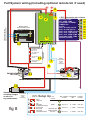
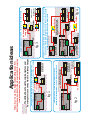
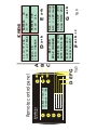
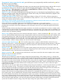
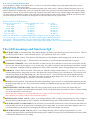
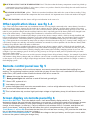
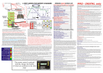
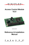
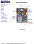
BB121250
BB122430
STERLING POWER PRODUCTS
BATTERY - to - BATTERY CHARGER
Advanced charging technology
REMOTE CONTROL (OPTION)
Battery-Battery
Charger
1
14.4 V
40.2 A
on/off
timer
134 min
2
3
4
alarm
light
1 Alarm shutdown
2 System disengaged
3 Low input voltage
4 System o.k.
Sterling power products
ORDER NO: BBDRC
Installations Instructions
& manual
Installations- und
Bedienungsanleitung
CE
Full System wiring.(including optional remote kit if used)
+ +4
15 amp fuse
15 amp fuse
3
2
L.E.D. information and alarms
BATTERY TYPE
ALT OVER TEMP
CONSTANT CURRENT
TIMMER ON
FLOAT
BATT IN OVER VOLTS
BATT IN LOW VOLTS
BATT OUT OVER VOLTS
BATT OUT LOW VOLTS
BATT OUT OVER TEMP
HEATSINK OVER TEMP
DEVICE FAILURE
Remote control
and information panel
( optional remote kit )
Power Battery-Battery
Management Charger
with
AMP Hr Counter
1
on/off
14.35
v m Timer
Pos 4
Bat
14.4v
37amps
435 134m
a/hrs
Alt
15.4v
alarm
light
2
System
Amps
System Trip
System Disengaged
Low voltage warning
System Within Limits
Amp
hr
4
5
Volts
1
2
3
4
Sterling
Sterlingpower
powerproducts
products
CE
CE
ON
13
2
3
6
1 2
NON SEALED LEAD ACID
OR TRACTION
LED YELLOW
1 2
GEL / EXIDE SPEC.
LED GREEN
ON
1 2
GEL USA SPEC
LED OFF
ON
12
BATTERY TYPE SELECTOR
SWITCH SETTINGS
ON
Battery
temperature
sensor
cable
( supplied )
7
1 2
SEALED ACID/ AGM
LED ORANGE
ON
8
ENGINE STARTER
BATTERY
14
15
16
17
18
19
20
21
22
23
24
25
1
auto pause remove
push 1 and 2 together
1
11
remote sensor
ENSURE ALL NEGS ARE COMMON
9
DOMESTIC BATTERY SYSTEM
10
1 2
ON
ON
1 2
1 2
1
2
3
4
ON
BATTERY
SELECTOR
1 2
fig 8
Alternator
temperature
sensor
cable
( supplied )
ON
alternator
or battery charger
or solar cell
any power source
Setup Up
OPEN
LEAD ACID
GELBATTERIES
(EXIDE SPECIFICATION)
SEALED LEAD
ACID & AGM
GEL & AGM
(USA SPECIFICATION)
LED
COLOUR
MAX. CHARGING
VOLTAGE
ABSORBTION
TIME
FLOATING
VOLTAGE
YELLOW
14.8V / 20°C
1 - 3 HRS.
13.65V / 20°C
GREEN
14.4V / 20°C
10 - 12 HRS.
13.8V / 20°C
GREEN-YELLOW
14.4V / 20°C
4 - 8 HRS.
13.65V / 20°C
GREEN FLASHING
FOR 5 SEC.
14.1V / 20°C
4 - 10 HRS.
13.5V / 20°C
fig 1
starter motor
Starter battery
d/c battery
charger
domestic/aux
battery bank
alternator
fig 2
starter motor
engine
d/c battery charger
Starter battery
Bow thruster
battery bank
domestic/aux
battery bank
already installed split charge
diode/relay/voltage amplifier
Installation to add a extra battery bank to a already
existing split charging system, ie a bow thruster battery bank
alternator
engine
Standard simple installation for auxiliary charging system on a
Small boat inboard or outboard , or a vehicle, 4 x wheel drive , or camper
The dotted line shows the original system and
how simple it is to connect the d/c battery charger
fig 3
starter motor
d/c battery charger
Starter battery
d/c battery
charger
Bow thruster
battery bank
domestic/aux
battery bank
starter motor
starter motor
gen set 2
alternator
engine
alternator
d/c battery charger
fig 4
domestic/aux
battery bank
d/c battery charger
Starter battery
already installed split charge
diode/relay/voltage amplifier
Starter battery
main
engine
gen set 1
alternator
This shows a simple installation where a boat may have a very large battery
bank and you wish to utilise all surplss power on the boat to ensure the
maximum charger is going into the main battery bank
engine
alternator
engine
Simple installation if you wish to charge 2 x extra battery banks
Application ideas
This unit can be used to charger extra battery banks from
Boat Inboard engines, Boat Outboard engines Vehicle engines
( cars/lorries/vans )and Generator engines
4
3
2
1
InBat v=13.7v
Current = 38A
1 Alarm shutdown
2 System disengaged
3 Low input voltage
4 System o.k.
Sterling power products
Battery-Battery
Digital Charger
CE
A
B
C
fig 5
DEFG
light
alarm
on/off
Remote control panel
F
a+b + c
R:v2.0 C:v2.0
12vIN-12vOUT
G
fig 6
a+b
Case LHS= 30c
Case RHS= 25c
PAUSE IN 19 MIN
AUTO PAUSE ON
a+b
Bat = +20 degc
Alt = +20 degc
E
WET OPEN
BULK CHARGER
a+b
BATTERY OUT
14.2V 31A
20min ON
17min CHARGE
D
BATTERY
IN
13.7V
38A
in 13.7V 23A
out 14.4V BULK
SCREENS
Why do I need the d/c battery charger?
By now I hope most people understand that the best way to charge a battery is using a 4 step battery
charging curve, which cannot be achieved from a standard alternator . This system enables one to simply
attach the unit to a standard engine battery and it will fool the alternator into working at its maximum ability
in order to ensure all its surplus power, utilised to charge the auxiliary battery bank to its maximum. This
system is designed to use only the surplus power. It ensures at all times, that the power required to run the
primary system as the vehicle system or the boat engine is not effected. The surplus power is converted into
a higher voltage and is used to charge a secondary battery bank using a digitally controlled programable 4
step charging curve whose unit is also totally isolated; i.e. the starter battery cannot discharge through this
system, even in the event of the unit failing.
What does it do?
In a nut shell it charges your extra battery system about 5 times faster than it would otherwise charge and put
about 50% extra use full power into them, and increases the life of the battery by de-sulphating them . For
best effect use open lead acid batteries. Avoid gel, sealed and AGM batteries. Even though open lead acid
batteries are by far the best for fast charging and longer life using advanced charging units. There is
sometimes no choice but to use gel or AGM. The unit has the settings to enable these to be charged within
their recommended charging curves.
Advantages of this unit.
1) installation: it does not get any easier. Simply connect to your starter batteries and to your domestic
battery. Job done. Low costs.
2) no direct connections to the standard engine alternator , or to the outboard, if used, thus on new
installations there is no extra wiring for a split charger system.
3) ensures the engine battery if maintained and well looked after
4) mutable units can be used, for example if you have a 60 amp alternator, and 3 battery banks ( engine,
domestic, and bow thruster ) then 2 of these can be used to run the bowthruster and the domestic system
.There, internal programs will adjust their charger patterns to accept the other unit. Ensure only the excess
power is used and the primary system is not placed in jeopardy.
5) ensures there is no voltage rise on the engine management system , to ensure no alarms or damage to the
system. Be it a outboard, or a car, or a boat
6) no vehicle warrantee issues as you are not connected to the main system
7) the unit isolated both battery banks and prevents any feed back through the unit
How does it work?
The unit monitors the engine start battery. This unit will not start until the battery voltage exceeds about 13
volts, then it waits for 2.5 min. to ensure that some charger is replaced quickly into the engine start battery.
After that, it pulls the engine battery down to no less than 13 volts, which enables the engine battery to still
receive a small charge and ensures the alternator works at its full potential. To further, ensure the engine
battery is o.k. Every 20 min. the unit stops for about 3 min. to ensure the engine battery charge is o.k. The
unit takes the 13 volts into the control box and then boosts this up to 14.8, or what ever voltage the unit is set
at( determined by the battery type dip switch settings ), in order to fast charge the other set or sets of
batteries. After a period of time, calculated by the software, when the auxiliary batteries are full, the system
will float the batteries at 14 volts, but always ensuring the engine battery comes first
Other features included in this system are 2 x temperature sensors, an alternator- and a battery temp sensor.
There is also a remote battery sensor and a fully automatic sleep sensor, which switches the unit off when the
engine has stopped. A remote panel is available as an optional extra
Installation see fig 8
Set this unit as you would any other high power battery charger, fit it as close to the batteries as possible in a
cool dry ventilated space. As with most ideal conditions on a boat, the cool well ventilated part is a bit of
wish full thinking, with this in mind you may notice that the unit comes with a heat sink and 3 x cooling
fans. Do not be surprised if in Northern Europe you never see these fans running, as the unit is designed for
a 40 deg C ambient running.
So if you have to fit it in a hot engine room then it should be o.k. but try to fit it low down on the bulk head
as it will be a little cooler there than at the top of the engine room.
Wiring : connect the output positive cable first, then the input positive cable then the negative, remember the
unit has a sleep and auto start , if the input voltage is above 13 volts ( due to a battery charger being on etc ,
then the unit will auto start.)
Program the battery type into the unit, go to the battery type program dip switches on the unit 12 and set
the battery type accordingly.
There are 3 main battery types,
Non sealed lead acid or sealed lead acid, where you can unscrew the lid of the battery and are able to top it
up with water, these are by far the best type for fast charging and long life. ( max voltage 14.8 )
Gel / Exide spec. This program is, as per the recommendation of Exide, set at a voltage of 14.4 volts for
about 10-12 hrs. The unit drops then to float.
Gel U.S.A. spec. For some reason known to someone but not to us, the American gel manufactures want a
different charging regime than the European ones. Don't ask us why, if in doubt as the battery supplier, this
setting has a max charger voltage of 14.1 volts.
Sealed lead acid/ A.G.M. This is set to a maximum charger voltage of 14.4 with a software program to
match most of these battery types, some AGM batteries only want 14.1, if so, set the unit to the American gel
setting. If in doubt ask the battery supplier
My advise is where possible use the open lead acid batteries, which are also by far the lowest cost . Due to their
slow recharge rate, avoid gel batteries for fast charging cycles.
Fit the unit as close as possible ( taking into account the above requirements ) to the supply batteries.
If you must fit it in an enclosed engine room ( i.e. a small yacht , where the engine room is fully enclosed with sound
proofing all over the place ,then fit any equipment as low as possible. Its best to fit it outside the engine room near the
battery box.
Always remember, that the only thing in the engine room that is air cooled is your alternator. If you have a totally sealed
room then don’t be surprised when you go through alternators on a regulator basis. If the engine room is sealed then put a
vent tube from outside to the back of the alternator, the alternator will suck air through the back and cool itself. Then you
will never have any alternator problems.
Battery temp: Simply connect one of the enclosed temperature sensor to a battery terminal post 6 ( neg. or pos. ), and
to the 2 x small terminals marked battery temp. simply push the small lever down and insert one wire into each side, there
is no polarity on these wires. make sure you do not crush the temp sensor which is a small thing inside the yellow ring
terminal, as this will destroy the processor chip. The output voltage will be reduced in accordance with manufacturers
battery charging temperature curves and in the event of the battery temperature increasing due to battery failure, it
exceeds 50 deg C, which is a major problem, the unit will switch off the charger .
Alternator high temp disengage: 10 This is another temp sensor ( supplied ) which should be connected to your
alternator output post ( b+ ) and will disengage the amplifier in the event of the alternator reaching 100 deg C. LED does
simply inform on the remote when the alternator reaches the temperature. When the alternator cools down a little, the
system automatically reengages and carries on .
Domestic sense: 8 As standard this unit senses all the control voltages at the unit, however if you want to sense the
voltage at the domestic battery direct, to over come the voltage drops in the cable run drops, then simply connect a cable
from the domestic sense connection direct to the domestic battery
Remote control kit: 13 An optional extra with this unit is the remote control kit, this comes complete with a remote
display, See fig 5-6 for remote operation.
Start up and test procedure
When the unit is connected, it senses the output voltage from the input battery, if the voltage is above 11 volts then the
system will come on for about 5 min., it will then work out that the input battery is to low to do anything and shut its self
down into sleep mode, the only way to start the system up then is to increase the input battery voltage by either switching
the engine on or start a battery charger. When the unit first starts up then the top battery type LED should show yellow
red or green, depending on the battery type selected, and the constant current LED ( 3 down ) will flash slowly. This green
LED should slow flash, which shows that the unit is working but is inactive for the first 2.5 min. to allow the engine
battery to recover a little.
After about 2.5 min. the green light will stop flashing and go onto green continuous, or shut the system down to rest mode
if the battery voltage is to low. The chances are, that the engine load, which is the system on constant current, will
increase while the unit should be boosting the current into the domestic battery bank. This high current will continue for
about 20 minutes then it will stop for 3 min. to allow ensure the engine battery is o.k..
Once the domestic battery reaches a certain voltage ( depending on the battery type setting but between 13.5-14 v) , the
trimmer LED will come on and high charge rate will continue for a calculated time period ( never the same ) see fig 8
lower right of page , the box marked setup. This time period is determined by what battery type program you select and
the state of charger of the batteries. The rest periods is 3 mins every 20 mins, After the time is over, the unit drops to float
at 14 volts at constant voltage with no switch off period. The unit will attempt to hold the battery voltage. However, if the
output battery falls below about 12.8 volts for more than 15 mins , the system will reset into the boost charger mode again.
also it the input voltage fall below 12.8 volts, the system will assume, that the input is switched off and will switch the
system into rest mode to conserve energy. Only if the input voltage rises again, will the system restart.
If on start up nothing happens, then
1) test the battery voltage. It should be above 11 volts, to see the unit working start up the engine and ensure you are
getting at least 13.5 volts at the battery.
Auto pause switch off. The units has a automatic program cycle which works 3 minuets off and 20 minuets on etc etc
until the batteries are charger, this cycle is to ensure the engine start system is well looked after and is bias in the engine
starter battery's favour. If you wish to remove the 3 minuet rest period ( which is o.k. and the engine start battery will be
o.k., then simply push button 1 and 2 at the same time ( this can only be done on the remote ) bold the two buttons until
you hear a beep, the screen will then say auto pause off. this will auto reset on system restart.
WHAT CABLE TO USE IN mm sq
A charger or inverter up to
cable run distance 0-1.5 mtr
1.5 4 mtr
0-25 amps
6 mm sq
10 mm sq
25-45 amps
16 mm sq
25 mm sq
45-85 amps
25 mm sq
35 mm sq
85-125 amps
35 mm sq
50 mm sq
125- 180 amps
50 mm sq
70 mm sq
180-330 amps
70 mm sq
90 mm sq
Please note that if there is a problem obtaining for example 90 mm sq cable, simply
Use 2 x 50 mm sq , or 3 x 35 mm sq , the cable is simply copper, and all you require
Is the copper , it does not matter if it is one cable or 10 cables as long as the square
area adds up. Performance of any product can be improved by thicker cable, so if in doubt round up
The LED meanings and functions fig8
14 BATTERY TYPE Tri Coloured LED: This simply displays the battery type that the processor has been set to. This is a
tri coloured LED. Yellow = open lead acid, Green = gel /sealed lead acid . Red = AGM..
15 ALT OVER TEMP : Yellow: This monitors the temperature of the alternator and disengages the unit in the event of
the alternator reaching 90 deg C, which waits for the alternator to cool down then automatically re-engages.
16 CONSTANT CURRENT: Green: This should be on from start up( slow flash shows unit on but on rest mode, for the
first 2.5 min. On start up and approx. every 20 min after, see graph ) and shows that the alternator should be working
at it’s maximum. It should remain on until the green float comes on and this shows the high charge rate is complete.
17 TIMER ON : Yellow: Timer Activated: This comes on, when the voltage reaches about 13.9 - 14 volts ( x 2 for 24 v )
and depending on how long it took to come, will dictate how long the timing cycle will remain on. The software will
calculate the timing for the high charge rate. This will vary from 1 - 6 hours and the time will be displayed on the
remote panel and a count down . This light will remain on until the high charge rate is over, and will go out at the
same time as the high charge rate between 1-6 hrs after activation.
18 FLOAT: Green Float Mode: This indicates that all the high charge cycles are now over and should remain on after all
the high charge lights are out. The system is now running at a standard charge rate only (about 14 volts) regulated on
the battery.
19BATTERY INPUT OVER VOLTS: This will warn you and switch off the boost section, this means that your
alternators own regulator has failed and the alternator will now boil and destroy your batteries, there is simply nothing
we can do about this except warn you:
please take this warning very seriously and stop your engine as soon as possible, remove the alternator input cable
then continue your journey and have the alternator repaired.
20BATTERY INPUT LOW VOLTS yellow: Low Voltage Warning: This is simply saying that there is a low voltage at
the main battery bank and has no active function. For information only, this usually indicates a defective alternator
21BATTERY OUTPUT OVER VOLTS: This will warn you and switch off the boost section, this means that either out
unit has failed and was in the process of overcharging your battery bank, or you have some other charging source on
your output battery bank which is overcharging the batteries and our unit thinks it is out unit
22BATTERY OUTPUT LOW VOLTS yellow: Low Voltage Warning: This is simply saying that there is a low
voltage at the output battery bank and that the charing unit is unable to keep up with your demand on the battery bank,
or the unit has failed and is not working.
23BATTERY OUTPUT OVER TEMPERATURE: Red : This shows that the battery temperature sensor has picked up
a temperature in excess of 50 deg C at its source ( where ever you have fitted it ) this will trip the unit until it has been
reset. Please find the fault before resetting
24 HEAT-SINK OVER TEMP. yellow: This device monitors both heat sinks and in the event of that exceeding 75 deg
C the unit will switch off until the temperature has been reduced. It is important not to fit the unit inside a hot engine
room
25 DEVICE FAILURE: red: this feature will give an indication in the event of a
Other application ideas see fig 1-4
Fig 1:This is the most common and easy installation because of being simply connected to the starter battery. In order to
connect up the d/c battery charger all you need to do is connect one wire from the auxiliary battery banks to the starter
battery. The starter battery stays between 13-14 volts ( within its limits ) and the domestic battery goes up to 14.4.-14.8. In
order to put a good fast charger into the auxiliary batteries, this is especially good if the battery bank to be charged is not
close to the starter battery , such as things like bowthrusters, or batteries in the boot of cars or lorries
Fig 2 :This option shows a standard split charger system on any boat or camper vehicle, which is already installed, and
has been using advanced alternator regulators or any other advanced charging system. An extra battery bank is required
such as a bow thruster, radio battery bank or a generator, for ease of installation simply drop on a d/c battery charger.
Fig 3:This option shows a situation on many boats or camper vehicles where there may be 3 x battery banks, simply put 2
x d/c battery chargers on, and they will ensure both banks are catered for, with no problem. the fact that one battery bank
is further away than the other will make no difference.
Fig 4 :This option shows a standard split charger system on any boat or camper vehicle, which is already installed, and
has been using advanced alternator regulators or any other advanced charging system. You will find out, that you wish to
supplement the marine house battery bank by charging with as many other auxiliary charging systems as you can. For
example: if you are running a gen set for 4 hrs per day you may as well put as much power as possible into your main
large house battery bank
Any source can be used. You can even use this system to charger from a old type battery charger , for example if you had a
old constant voltage battery charger and you wished to convert it into a constant current one, then simply put one of these
on the output. Or if you have a single output charger and want a dual output, then simply add one d/c charger to make a
dual charging system
Remote control panel see fig 5
A:
on/off: this switches off the unit boost aspect, but cannot prevent the standard diode splitting from
working. The monitoring functions remain in and the only way to know if the unit is switched off is the system
within limits ( LED )which will be off while the boost off will be on screen 3b
B: Alarm: this mutes the alarm system
C: Back ground light: this switches on and off the back ground light
D: Green LED, system all o.k.
E: Low battery input voltage
F: system disengaged, this is an auto recoverable alarm , such as a high alternator temp trip. This will come
back on when the temperature has reduced
G:This is a fatal alarm trip, such as high input/output voltage or high battery temp, this will alarm and switch
off
Screen display on remote panel fig 6
Screen D/a: BUTTON 1 This is the default screen. It will automatically display switch on. This screen is
designed to display the most relevant information on one screen, to remove the need to flick between screens.
This screen shows the battery in- and output voltage. It also shows the amps in the unit, and its state of
charge, ie bulk charger ( on start up ). Pause is when the unit switches off for 2.5 minutes, and the time will
show ( count down ), how long one has left before the cycle is complete and the unit goes onto float.
Push Button 1: screen D/b this shows the total time, the unit has been running ( ON ) and also the total time,
the unit has been charging in that time ( charge )
Screen E/a: Push button marked 2 , this shows the voltage on the input battery and its input current, which
is the one the system is taking the charge from )
Push button marked 2 again: screen E/b this displays the output voltage and current of the
battery you are charging. ( a less current but higher voltage )
Screen F/a: Push button marked 3 ( this is the setup information screen ) This screen gives different
information depending on the system cycle, it is informing you., WET OPEN= wet open lead acid cell batteries,
this shows that the system battery type dip switches are set for wet cell batteries,( 14.8 v max setting ) Bulk
charge refers to the initial charge rate, this could change to a timer, then adventually change to float ( float
charger 14 volts )
Push button marked 3 again: screen F/b. This screen shows the time left to the next pause cycle
( for 2.5 min. ) and that it is on auto. The auto can be removed by pushing buttons 1 and 2 together. This
removes the auto pause control, and the charger will still have all its safety and timing cycles, every 20 min.
pause
Push button marked 3 again: screen F/c. R:v2.0 C:v2.0, this shows the software version for
remote ( R ) and for main PCB ( C ). the 12vIN-12vOUT, refers to the motel, a 12v-12v unit. There are 12-24 v,
24-24 and 24-12.
Screen G/a: Push button marked 4.: There are 2 x screens on this button. Push once for screen a, then
again for screen b. Screen a shows the alternator temp and the domestic battery temp, if the temperature
sensors are not fitted it will default to 20 deg C
Screen G/b:: Push button marked Temp 4a+b: There are 2 x screens on this button. Push once
for screen a, then again for screen b. Screen b shows the box heat sink temperatures, LHS stands for left hand
side, Guess what RHS stands for.
Do not expect these to be the same temperature
Pre set voltages: ( x 2 for 24 v models )
Minimum input voltage the unit will run at 13 volts
Voltage the unit switches off and drops into sleep mode
below 12.8 v for at lease 15 mins
Power consumption on sleep mode. 5 ma ie 0.005 amps
max input voltage trip 15.5
max output voltage trip 15.5
All voltages refer to a default temperature of 20 deg c
if the battery temperature sensor is fitted these voltages will be less depending on
the battery temperature
Alt temp disengage 100 deg C
Reset alt
80
Battery temp trip
50 deg C
Heat sink trip
70 deg C
Heat sink reset
60 deg C
Fans on at
50 deg C
Fans on over
35 amps
Fans of at
45 deg C
Low battery alarm
1 2.5 v
Low battery regulation 13 v
high battery voltage trip 15.5v
Max input current at 12 v = 45 amps
amp meter +/- about 10%
voltmeter +/- 1%