1
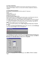
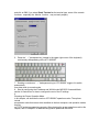
ATC-2000WF User’s Manual The software described in this manual is furnished under a license agreement and may be used only in accordance with the terms of that agreement. Copyright Notice Copyright 2007 ATC Technology Co., Ltd. All rights reserved. Reproduction without permission is prohibited. Trademarks ATC is a registered trademark of The ATC Technology Co.,Ltd. All other trademarks or registered marks in this manual belong to their respective manufacturers. Disclaimer Information in this document is subject to change without notice and does not represent a commitment on the part of ATC 1.0 Introduction ATC-2000WF Series of wireless serial device servers give you an easy way to connect your RS-232/422/485 serial devices to a WLAN. The 1-port ATC-2000WF and 2-port ATC-2002WF are ideal for environments where a LAN is not available, or where serial devices are moved frequently. 1.1 Overview The RS232 connection application has been used for a long time. RS232 cable has limitations in distance. WLAN (Wireless Local Area Network) has become a worldwide standard protocol for wireless applications. There are many applications for using RS232 connection over WLAN, including POS, data capture, telemetry, PLC controllers, remote control, vending machine, industrial control, and others. The device that supports connection over WLAN is called as Wireless to Serial Server. Through out the guide, the 802.11g Wireless to Serial Server will be referred as the“Server”. ATC-2000WF wireless serial device servers support automatic IP configuration protocols (DHCP, BOOTP) and manual configuration via a handy web browser console. Both IP configuration methods ensure quick and effective installation, An external antenna increases the range of the wireless connection. Users can position the adjustable antenna for maximum signal strength or even replace the antenna with their own for additional flexibility and scalability. This feature is particularly useful when a serial device is connected in a high interference area. As an added feature, a signal strength indicator is located on the front panel to make it easier to troubleshoot connection Problems. ATC-2000WF wireless serial device servers ensure the compatibility of network software that uses a standard network API by providing TCP Server Mode, TCP Client Mode, and UDP Mode. The Real COM/TTY drivers allow software that works with COM/TTY ports to be set up to work over a TCP/IP network in no time. This excellent feature preserves your software investment and lets you enjoy the benefits of networking your serial devices instantly. To make your management task easier, the ATC-2000WF provides additional features, such as password authentication, IP filter, WEP support for 64-bit and 128-bit encryption, and SNMP support. 1.2 Package Content ●One 802.11g Wireless to Serial Server ●One Removable Antenna (RP-SMA) (“Reverse Polarity – SMA”) ●One CD (containing Set Up Utility, User Manual and various Application Notes) ●One AC Power Adapter with DC barrel plug (2.1mm ID, 5.5mm OD) ●One RS-232 DB9 Female Cross Configuration cable ●One Quick Installation Guide Optional Accessories ●DK-32A DIN-Rail Mounting Kit (32 mm) NOTE: Notify your sales representative if any of the above items is missing or damaged. 1.3 Product Features ●Connect serial device to Wireless LAN network ●802.11b Wireless LAN, compatible with 802.11g ●WEP support for 64-bit and 128-bit encryption ●Password authentication and IP filter ●Ad-Hoc(peer-to-peer), Infrastructure, Pseudo IBSS mode support ●RS-232 Serial Port for console ●3 in one RS-232/422/485 port can be freely chosen, at up to 115.2 Kbps ●Versatile socket operation modes, including: TCP/IP, UDP/IP, HTTP, ARP, DHCP client ●Easy-to-use Windows Utility for mass installation ●Supports Windows Virtual COM drivers ●LEDs indicate LINK, DIS, ACT and PWR. WLAN Radio Features: Protocol Type: 802.11b standard compliant Operating Range: Open Environment: 1000 ft./300m Office Environment: 100-330 ft./30-100m Security: WEP (Wired Equivalent Privacy) 64 and 128 bit encryption Network Mode Infrastructure mode, Ad-Hoc mode 1.4 Serial Communication Parameters No. of ports:1 (ATC-2000WF) Interface: RS-232/422/485 Port Type:DB9 Male and six bit terminal Baud Rate Options: 9600, 38400, 57600, 115200 bps Data Length Options: 8 bits Parity options: None Stop Bits Options: 1 bit Flow Control: Hardware or none Serial UART Buffer: 256 bytes input, 256 bytes output Radio Characteristics: Spread Spectrum Technology: DSSS (Direct Sequence Spread Spectrum) RF Range: 2.4 ~ 2.4835 GHz Data Rate: 11 / 5.5 / 2 / 1 Mbps Modulation: DBPSK for 1 Mbps, DQPSK for 2 Mbps, CCK for 5.5 / 11 Mbps Operation channels: US - 11, Europe - 13, France - 4, Spain - 2, Japan - 14 RF Power Output (Typ.): +15 dBm Receive Sensitivity (Typ. @BER 10E-5): -83 dBm@11Mbps Power: Power Supply: 9-36VDC Current: Tx 350mA (Max.), Rx 210mA, Power Saving Mode 80mA Software: Windows-based Driver with Multi -Link Virtual Com Driver PC Set UP Utility: User setup and device-search software run on Windows XP/ 98 / ME / NT / 2000 Network Protocol: TCP/IP, UDP/IP, SNMP, HTTP, ARP, DHCP client Mechanical: Antenna: PCB board-mount antenna option, or Ipex connector for external antenna and cable option Dimensions: 95 x 76 x 26 mm) Environmental: Temperature: Operating: 0 to +55 °C / +32 to +131 °F Storage: -20 to +65 °C / -4 to +149 °F Relative Humidity: 95% (non-condensing) Emissions EMC Certificate: U.S.A.: FCC Part 15 Subpart C CE: ETSI EN 300 328, EN 301 489-1/17, EN 55022, EN 61000, EN 50371 Certification: Some models are already FCC Modular-Certified for immediate public sale. 1.5 Serial Port Pin Assignments RS-232/422/485 Pinouts RS-232 Pinout(DB9 Female ) PIN 2 3 5 7 8 RS-232 RXD TXD GND RTS CTS Input/Output I O O I RS-422/485 Pinout(SIX Terminal from Left) PIN 1 2 3 4 5 6 RS-422 T+ TR+ RVIN+ VIN- RS-485 485+ 485NC NC VIN+ VIN+ 1.6 Connecting the Hardware This section describes how to connect ATC-2000WF to serial devices for first time testing purposes. We cover Wiring Requirements, Connecting the Power, Connecting to the Network, You should also pay attention to the following items: Use separate paths to route wiring for power and devices. If power wiring and device wiring paths must cross, make sure the wires are perpendicular at the intersection point. Connecting the Power Connect the 9-36 VDC power line with ATC-2000 power jack. When the power is properly supplied, the .Link and DIS. LED will light in red and yellow color until the system is ready, at which time the .Link. LED will be put out and DIS PWR LED still light. Connecting to a Serial Device Connect the serial data cable between ATC-2000WF and the serial device. 1.7 Top Panel LED Indicators LINK ---- Indicate WLAN status DIS ---- Indicate WLAN status ACT ---- It will flash when transmit the data from WLAN to serial or from serial to WLAN. PWR ---- Indicate the Power supply Detail for LINK,DIS Led indicate LINK OFF ON OFF ON DIS OFF OFF ON ON Status WLAN Connecting WLAN Connected WLAN Disconnect Setup Command 2.0 Initial Configuration When setting up your ATC-2000WF for the first time, the first thing you should do is configure the IP address. Select one of the initial IP Address configuration methods to configure 2.1 Factory Default IP Address ATC-2000WF is configured with the following default IP addresses: WLAN: Setting static IP IP Address 192.168.1.250 Netmask 255.255.255.0 2.2 Serial Console (19200, n, 8, 1) Before configuring the ATC-2000WF via the serial console, turn off the power and use a serial cable to connect the ATC-2000WF to your computer’s serial port. We suggest using PComm Terminal Emulator, which is available in CD driver to carry out the configuration procedure. Firstly install PComm Terminal Emulator on your computer. 1. Connect ATC-2000WF RS-232 serial port directly to your computer’s male RS-232 serial Port with RS-232 DB9 Female Cross Configuration cable 2. From the Windows desktop, click on Start # Programs # PComm Lite # Terminal Emulator. 3. When the PComm Terminal Emulator window opens, first click on the Port Manager menu item and select Open, or click on the Open icon. 4. The Property window opens automatically. From the Communication Parameter page, select the appropriate COM port for the connection, COM1 in this example, and 38400 for Baud Rate, 8 for Data Bits, None for Parity, and 1 for Stop Bits. 5. From the Property window.s Terminal page, select ANSI or VT100 for Terminal Type, and click on OK. If you select Dumb Terminal as the terminal type, some of the console functions—especially the .Monitor. function—may not work properly. 6. Press the “ ←” backspace key (located in the upper right corner of the keyboard) continuously whilepowering on the ATC-2000WF . 7. Sending a continuous “ ←” backspace string to ATC-2000WF triggers it to switch automatically from data mode to console mode. 8. Start by configuring the IP address and WLAN under MS-DOS Command Mode. section for instructions on how to configure the rest of the IP settings. 4 Choosing the Proper Operation Mode In this chapter, we describe the various ATC-2000WF operation modes. The options include an operation mode that uses a driver installed on the host computer, and operation modes that rely on TCP/IP socket programming concepts. After choosing the proper operation mode in this chapter, refer to Chapter 5 for detailed configuration parameter definitions. 3.0 Summary of Commands – Listed by Functional Category (These commands are explained in detail with more detailed functioning examples further in this document.) Network Commands IP xxx.xxx.xxx.xxx Where x is the IP of this device MASK xxx.xxx.xxx.xxx Where x is the Network Mask of this device GW xxx.xxx.xxx.xxx Where x is the Gateway of this device DHCP x Where x is the DHCP setting: 1=ON 0=OFF Wireless LAN Commands CHAN x Where x is the channel setting 1-14 MODE x Where x Network Mode x = a(ad hoc) b(infrastructure) p(Pseudo IBSS) SSID xxxxxxxxx Where x is the multi-character SSID network name RATE x Where x is the Tx rate, 1,2,5,11 mbps WEP x Where x is WEP key 0=OFF, 1=64bit, 2=128bit WK x yyyyyyyyyy Load WEP Encryption Key into WEP buffers 1, 2, 3 or 4 WKID x Where x is the Buffer of the WEP encryption key in use 1, 2, 3 or 4 AA x Where x is the authentication: A=Auto, S=Shared Key, O=Open Serial Port Commands BAUD x Where x is serial port baud rate, 0=115200, 1=57600, 2=38400, 3=9600 FCTL x Where x is Serial Flow Control setting, 1=ON, 0=OFF PORT xxxxx Where x= TCP Serial Port Number (Default value is “1001”) Server/Client Settings RMODE x Where x is CLIENT or SERVER setting for this device RIP xxx.xxx.xxx.xxx Where x is Server Target Remote IP when this device is in Client mode. RPORT xxxxx Where x is Server Target Remote PORT when this device Client mode. Enter Command Mode SetUpWLAN Gatekeeper Command Entry String Exit and Save Settings Commands EXIT Exits Command Mode but DOES NOT SAVE CHANGES SAVE SAVE Command (Saves only but does not Exit Configuration Mode.) SE SAVES and EXITS Command Mode simultaneously Other Commands PSMOD x Where x is the power saving mode: 1=ON 0=OFF RES Reset as if a Hardware reset was applied DEF Restores all settings to Factory Default MAC Read-Only command that display the unique MAC address VER Read-Only command returns Firmware Version Number HELP Displays list of all available Commands along with abbreviated format LIST Displays alphabetic readout of all Mini-b Settings