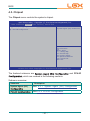
1
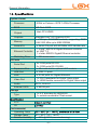
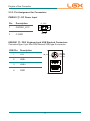
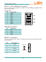
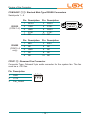
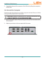
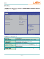
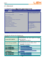
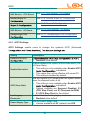
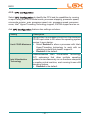
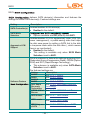
AU95C Series Robust Embedded System with Intel® Celeron ® 827E Processor User’s Manual Version 1.0 P/N: 4012165000100P 2012.11 1 Contents Chapter 1 - General Information.......................................................1 1.1. Introduction ...................................................................................... 2 1.2. Product Highlights ............................................................................ 2 1.3. Ordering Information ........................................................................ 3 1.4. Packing List...................................................................................... 4 1.5. Optional Accessory .......................................................................... 4 ....................... 4 ................................................................................... 6 1.9. Dimensions ...................................................................................... 8 1.10. External Controls and Connectors ................................................. 9 Chapter 2 - Engine of the Computer .............................................. 11 2.1. Board Layout.................................................................................. 12 2.1.1. CPU Board........................................................................... 12 2.1.2. Carrier Board ....................................................................... 13 2.2. DIP Switches and Connectors ....................................................... 15 2.2.1. List of DIP Switches and Connectors .................................. 15 2.2.2. DIP Switch Setting ............................................................... 16 2.2.3. Pin Assignment for Connectors ........................................... 20 Chapter 3 - Installation and Maintenance......................................27 3.1. Remove Bottom Cover................................................................... 28 3.2. Install Wi-Fi Module (Optional)....................................................... 29 3.3. Install/Uninstall CFast Card ........................................................... 30 3.4. Wall Mount ..................................................................................... 31 3.5. DIN-Rail Mount .............................................................................. 32 3.5.1. Dismount from DIN-rail ........................................................ 34 3.6. Ground the Computer .................................................................... 35 3.7. Wire the DC-Input Power Source................................................... 36 -i- Contents Chapter 4 - BIOS ..............................................................................55 4.1. Main ............................................................................................... 58 4.2. Advanced ....................................................................................... 60 4.2.1. ACPI Settings....................................................................... 61 4.2.2. ............................................................... 62 4.2.3. .............................................................. 63 4.2.4. ............................ 67 4.2.5. ............................................................... 68 4.2.6. ............................................................... 71 4.2.7. H/W Monitor -CPU Board ................................................... 72 4.2.8. ........................................... 72 4.2.9. ........................................................ 75 4.2.10. H/W Monitor -I/O Board .................................................... 76 4.2.11. ........................................ 76 4.3. Chipset ........................................................................................... 78 4.3.1. ........................................ 79 4.3.2. .......................................................... 87 4.4. Boot................................................................................................ 93 4.5. Security .......................................................................................... 94 4.6. Save & Exit .................................................................................... 95 Appendix ..........................................................................................97 A: Watchdog Timer (WDT) Setting ....................................................... 98 - ii - Preface Copyright Notice All Rights Reserved. The information in this document is subject to change without prior notice in order to improve the reliability, design and function. It does not represent a commitment on the part of the manufacturer. Under no circumstances will the manufacturer be liable for any direct, indirect, special, incidental, or consequential damages arising from the use or inability to use the product or documentation, even if advised of the possibility of such damages. This document contains proprietary information protected by copyright. All rights are reserved. No part of this document may be reproduced by any mechanical, electronic, or other means in any form without prior written permission of the manufacturer. Declaration of Conformity CE The CE symbol on your product indicates that it is in compliance with the by contacting Technical Support. shielded cables are used for external wiring. We recommend the use of shielded cables. This kind of cable is available from Logic Supply. Warning This is a class A product. In a domestic environment this product may cause radio interference in which case the user may be required to take adequate measures. FCC Class A This device complies with Part 15 of the FCC Rules. Operation is subject to the following two conditions: (1) This device may not cause harmful interference, and (2) This device must accept any interference received, including interference that may cause undesired operation. NOTE: This equipment has been tested and found to comply with the limits for a Class A digital device, pursuant to Part 15 of the FCC Rules. These limits are designed to provide reasonable protection against harmful interference when the - iii - Preface equipment is operated in a commercial environment. This equipment generates, uses, and can radiate radio frequency energy and, if not installed and used in accordance with the instruction manual, may cause harmful interference to radio communications. Operation of this equipment in a residential area is likely to cause harmful interference in which case the user will be required to correct the interference at his own expense. RoHS LGX Systems certifies that all components in its products are in compliance and conform to the European Union’s Restriction of Use of Hazardous Substances in Electrical and Electronic Equipment (RoHS) Directive 2002/95/EC. The above mentioned directive was published on 2/13/2003. The main purpose of the directive is to prohibit the use of lead, mercury, cadmium, hexavalent chromium, polybrominated biphenyls (PBB), and polybrominated diphenyl ethers (PBDE) in electrical and electronic products. Member states of the EU are to enforce by 7/1/2006. LGX Systems hereby states that the listed products do not contain unintentional additions of lead, mercury, hex chrome, PBB or PBDB that exceed a maximum concentration value of 0.1% by weight or for cadmium exceed a substance or mixture of substances with uniform composition (such as solders, resins, plating, etc.). Lead-free solder is used for all terminations (Sn(96-96.5%), Ag(3.0-3.5%) and Cu(0.5%)). SVHC / REACH To minimize the environmental impact and take more responsibility to the earth LGX (Substances of Very High Concern) in (EC) 1907/2006 (REACH --Registration, Evaluation, Authorization, and Restriction of Chemicals) regulated by the European Union. All substances listed in SVHC < 0.1 % by weight (1000 ppm) - iv - Preface Important Safety Instructions Read these safety instructions carefully 1. Read all cautions and warnings on the equipment. 2. Place this equipment on a reliable surface when installing. Dropping it or letting it fall may cause damage 3. Make sure the correct voltage is connected to the equipment. 4. For pluggable equipment, the socket outlet should be near the equipment and should be easily accessible. 5. Keep this equipment away from humidity. 6. The openings on the enclosure are for air convection and protect the equipment from overheating. DO NOT COVER THE OPENINGS. 7. Position the power cord so that people cannot step on it. Do not place anything over the power cord. 8. 9. Never open the equipment. For safety reasons, the equipment should be 10. If one of the following situations arises, get the equipment checked by service personnel: a. The power cord or plug is damaged. b. Liquid has penetrated into the equipment. c. The equipment has been exposed to moisture. d. The equipment does not work well, or you cannot get it to work according to the user’s manual. e. The equipment has been dropped or damaged. f. The equipment has obvious signs of breakage. 11. Keep this User’s Manual for later reference. -v- Preface About This User’s Manual This User’s Manual is intended for experienced users and integrators with hardware knowledge of personal computers. If you are not sure about any description in this User’s Manual, please consult your vendor before further handling. Warning The Box PC and its components contain very delicately Integrated Circuits (IC). To protect the Box PC and its components against damage caused by static electricity, you should always follow the precautions below when handling it: 1. Disconnect your Box PC from the power source when you want to work on the inside. 2. Use a grounded wrist strap when handling computer components. 3. Place components on a grounded antistatic pad or on the bag that came with the Box PC, whenever components are separated from the system. Lithium Battery Replacement Incorrect replacement of the lithium battery may lead to a risk of explosion. The lithium battery must be replaced with an identical battery or a battery type recommended by the manufacturer. Do not throw lithium batteries into the trash can. It must be disposed of in accordance with local regulations concerning special waste. Technical Support Please do not hesitate to call or e-mail our customer service when you still cannot www.logicsupply.com E-mail: [email protected] - vi - Preface Warranty This product is warranted to be in good working order for a period of one year from the date of purchase. Should this product fail to be in good working order at any time during this period, we will, at our option, replace or repair it at no additional charge except as set forth in the following terms. This warranty does or disaster. other incidental or consequential damage resulting from the use, misuse of, or inability to use this product. Vendor will not be liable for any claim made by any other related party. Vendors disclaim all other warranties, either expressed or implied, including but purpose, with respect to the hardware, the accompanying product’s manual(s) and written materials, and any accompanying hardware. This limited warranty Return authorization must be obtained from the vendor before returned merchandise will be accepted. Authorization can be obtained by calling or faxing the vendor and requesting a Return Merchandise Authorization (RMA) number. Returned goods should always be accompanied by a clear problem description. - vii - 1 Chapter 1 General Information Chapter 1 - General Information -1- General Information 1.1. Introduction AU95C is a digital signage player meant for service industry to deliver AU95C is ideal for the PIS (Passenger Information System) for the mass transportation services such as train stations and airports. It also brings the brain for the kiosks in hotels and movie theatres. It is capable of the rich multimedia contents needed for the advertisement screens in the leisure places such as shopping malls and complexes. The computer is all about hospitality enhancement and customers touting for your business. 1.2. Product Highlights All-In-One Platform The CPU, DRAM and even software are integrated to provide a plug-andplay machine. Compact-sized The boards are based on a non-standard form factor to make the computer compact enough and consume only a little space. Fanless Design By using a low power processor, the system does not have to rely on fans, which are unreliable and often cause dust to circulate inside the equipment. Modular CPU Board The modularized CPU board facilitates the possible maintenance or upgrades to system. Systems based on a modular CPU board can be easily -2- General Information Powerful Networking The AU95C provides multiple COM ports, two Ethernet ports and six USB ports for data communication. Numerous Display/Video Output Integrated with an Intel® HD Graphics core, AU95C improves graphics and 3D rendering performance and supports the display/video output including DVI-I and HDMI. Advanced Storage AU95C comes with an eSATA port for fast data transfer speeds for external storage device and a CFast-card slot for better, faster and costeffective expansibility for more applications. Trustworthy The onboard Watchdog Timer can invoke an NMI or system reset when your application misbehaves within the system. 1.3. Ordering Information AU95C Barebone system w/ Intel® Celeron 827E storage and memory -3- General Information System Kernel Processor 1.5GHz or Celeron™ 827E 1.4GHz Processor BIOS AMI Flash BIOS Chipset Intel® PCH HM65 Integrated Intel® HD Graphics 3000 2 x 204-pin SO-DIMM sockets, supporting DDR3 Memory 1066/1333 MHz up to 8GB SDRAM Serial ATA 1 x Serial ATA port with 600MB/s HDD transfer rate 1 x Intel® 82579LM Gigabit Ethernet controller w/ iAMT 7.0 Ethernet Controller 1 x Intel® 82583V Gigabit Ethernet controller Watchdog Timer 1 ~ 255 levels reset I/O Ports 4 x COM ports RS-232 Serial Port 2 x COM ports RS-232/485 Expansion Bus 1 x Mini-card slot for optional WiFi module USB Port 6 x USB 2.0 ports LAN 2 x RJ-45 ports for Gigabit Ethernet 1 x DVI-I receptacle for Digital Video output Video Port 1 x HDMI female connector for Digital Video output Audio Mic-in, Line-out 1 x eSATA port External SATA Storage 1 x 2.5” drive bay for HDD/SSD Type 1 x outside accessible CFast socket Graphics FCC CE Environmental Operating Temp. Storage Temp. Relative Humidity -40 ~ 85ºC (-40 ~ 185ºF) 5 ~ 95% @ 40°C (non-condensing) -4- General Information Vibration Shock Mechanical Construction Mounting Weight Dimensions (W x D x H) Power Requirement Power Input Power Consumption 1 Grms/5~500Hz/random operation, CFast, 1G/SDD Operating 40G (11ms), Non-operating 80G with SSD Operating 20G (11ms), Non-operating 60G with HDD Aluminum alloy DIN-rail mount & wall mount 2.87 kg (6.32 lb) (Bare-bone) 228.5 x 155 x 65 mm (8.99” x 6.10” x 2.55”) DC 9-32V input Max. 38W -5- General Information 1.9. Dimensions 155 111.1 18 228.5 241.8 3 68 254.8 Unit: mm -6- General Information 1.10. External Controls and Connectors Front View KB/MS DVI-I CFast eSATA HDMI Line-out MIC-in PWR Button USB Ports Antenna Hole Rear View LAN Ports DC-IN USB Ports HDD LED COM Ports -7- 2 Chapter 2 Engine of the Computer Chapter 2 - Engine of the Computer - 8 - Engine of the Computer 2.1. Board Layout The CPU board and the carrier board together form the engine of the AU95C. 2.1.1. CPU Board Top View Sandy Bridge Processor PCH QM67/HM65 Bottom View COM Express® AB Connector COM Express® CD Connector COM Express CD Connector COM Express AB Connector - 9 - 11 PW1 4 COM C EH3 10 KBUSB1 D110 C110 B110 A110 1 19 8 CN3 3 COM B 3 COM A COM Express CD Connector COM Express AB Connector 9 AUDIO2 D1 C1 B1 A1 5 LAN2 14 CPUF1 7 ESATA1 PC1 S7 5 LAN1 13 LED1 6 CF1 12 PWRIN1 Engine of the Computer 2.1.2. Carrier Board PBC-9004: Board Top PC17 S1 - 10 - 9 ON 16 16 1 SATA1 9 ON 16 ON 9 8 7 6 5 4 3 2 1 8 7 6 5 4 3 2 1 5 6 7 8 ON 4 3 2 1 1 SW4 MC1 52 16 18 2 SW1 SW2 SW3 P15 P1 S7 S1 - 11 - 2 51 15 17 8 7 6 5 4 3 2 1 Engine of the Computer PBC-9004: Board Bottom 1 Engine of the Computer 2.2. DIP Switches and Connectors 2.2.1. List of DIP Switches and Connectors DIP Switches Board Side No. Bottom ᆺ Bottom ᆻ Label Function Clears/keeps CMOS setting Selects the BIOS from the CPU board or carrier SW4 board. Switches power supply between AT and ATX modes. SW1~3 Sets COM5~6 to RS-232 or RS-485. Connectors Board Side No. Label Description Bottom SATA1 Serial ATA connectors Bottom ཱ ི ཱི ུ ཱུ ྲྀ ཷ ླྀ ཹ Mini-card interface connector Top Top Top Top Top Top Top Top Top Top Top Top MC1 COM A/B COM1~4 RS-232 serial ports COM C COM5~6 RS-232/485 serial ports LAN1~2 Ethernet connectors (including USB connectors) CF1 CFast slot ESATA1 External serial ATA connector CN3 HDMI and DVI-I connectors AUDIO2 Audio jack connector (line-out/mic-in) KBUSB1 PS/2 keyboard connectors) PW1 Power button and ེ ཻ PWRIN1 DC power input HDD status LED ོ LED1 ཽ CPUF1 CPU fan connector - 12 - mouse (including USB Engine of the Computer 2.2.2. DIP Switch Setting 2.2.2.1. SW4 ᆺ: Clears/Keeps CMOS Setting The SW4 is a 8-pin and 4-toggle switch. It relies on its toggles 1 and 2 to clear/keep the CMOS setting of the computer. Toggle Position Function SW4 1 On 2 Off Keeps CMOS setting (default) Setting Toggle 1 Toggle Position Function SW4 1 Off 2 On Clears CMOS setting KE ON 2 3 4 Setting KE ON Toggle 1 2 3 4 2.2.2.2. SW4 ᆺ: Sets Power Supply Mode It relies on SW4’s toggles 3 to switch the power supply mode between AT and ATX modes. Toggle Position Function Setting KE ON 3 Off Sets the power supply to ATX mode (default) SW4 Toggle 1 2 3 KE ON 3 On 4 Sets the power supply to AT mode Toggle 1 - 13 - 2 3 4 Engine of the Computer 2.2.2.3. SW4 ᆺ: Selects BIOS from CPU Board / Carrier Board It relies on SW4’s toggle 4 to select the BIOS from either the CPU board or the carrier board. Toggle Position Function Setting KE ON 4 On Selects the BIOS from the CPU board SW4 Toggle 1 2 3 4 KE ON 4 Off Selects the BIOS from te carrier boards (default) Toggle 1 2 3 4 2.2.2.4. SW1, SW3 ᆻ: COM5 Data Transmission Interface Setting It relies on SW1 and SW3 to set the data transmission interface for COM5. To set COM5 to RS-232 or RS-485, apply the following setting: Ź RS-232 (Default) SW1 SW3 Toggle 1 2 3 4 5 6 7 8 Toggle 1 2 3 Pins 1 & 16 2 &15 3 & 14 4 & 13 5 & 12 6 & 11 7 & 10 8&9 Pins 1 & 16 2 &15 3 & 14 Position On On On On On On On On Position On Off Off 4 4 & 13 Off - 14 - Setting 16 15 14 13 12 11 10 9 KE ON 1 2 3 4 5 6 7 8 Setting 16 15 14 13 12 11 10 9 KE ON 1 2 3 4 5 6 7 8 Engine of the Computer Ź RS-485 SW1 SW3 Toggle 1 2 3 4 5 6 7 8 Toggle 1 2 3 Pins 1 & 16 2 &15 3 & 14 4 & 13 5 & 12 6 & 11 7 & 10 8&9 Pins 1 & 16 2 &15 3 & 14 Position Off Off Off Off Off Off Off Off Position Off On On 4 4 & 13 On Setting 16 15 14 13 12 11 10 9 KE ON 1 2 3 4 5 6 7 8 Setting 16 15 14 13 12 11 10 9 KE ON 1 2 3 4 5 6 7 8 2.2.2.5. SW2, SW3 ᆻ: COM6 Data Transmission Interface Setting It relies on SW2 and SW3 to set the data transmission interface for COM6. To set COM6 to RS-232 or RS-485, apply the following setting: Ź RS-232 (Default) SW2 Toggle 1 2 3 4 5 6 7 8 Pins 1 & 16 2 &15 3 & 14 4 & 13 5 & 12 6 & 11 7 & 10 8&9 Position On On On On On On On On - 15 - Setting 16 15 14 13 12 11 10 9 KE ON 1 2 3 4 5 6 7 8 SW3 Ź Toggle 5 6 7 Pins 5 & 12 6 & 11 7 & 10 Position On Off Off 8 8&9 Off Toggle 1 2 3 4 5 6 7 8 Toggle 5 6 7 Pins 1 & 16 2 &15 3 & 14 4 & 13 5 & 12 6 & 11 7 & 10 8&9 Pins 5 & 12 6 & 11 7 & 10 Position Off Off Off Off Off Off Off Off Position Off On On 8 8&9 On Setting 16 15 14 13 12 11 10 9 KE ON 1 2 3 4 5 6 7 8 RS-485 SW2 SW3 - 16 - Setting 16 15 14 13 12 11 10 9 KE ON 1 2 3 4 5 6 7 8 Setting 16 15 14 13 12 11 10 9 KE ON 1 2 3 4 5 6 7 8 Engine of the Computer 2.2.3. Pin Assignment for Connectors PWRIN1 ཻ: DC Power Input Pin Description 1 PWRIN1_VCC 2 C-GND 9 - 32V 1 + 2 - DC IN KBUSB1 ཹ: PS/2 Keyboard and USB Stacked Connectors Connector type: 6-pin Mini-DIN/Stacked USB type A connector USB Pin Description 1 +5V 2 USB- 3 USB+ 4 GND KB_CLK KB_GND KB_DAT KB_VCC 1 2 3 4 1 2 3 4 - 17 - Engine of the Computer LAN1~2 ུ: LAN + USB Stacked Connectors This connector supports USB 2.0 x 2 (USB0, 1) & 10/100Mbps or Gigabit RJ-45 Ethernet connection. LAN (RJ-45) Pin Description 1 MDI0+ 2 MDI03 MDI1+ 4 MDI15 MDI2+ 6 MDI27 MDI3+ 8 MDI3- LAN 8 1 1 2 3 4 USB 1 2 3 4 USB USB (Type A Connector) Pin Description 1 +5V 2 USB3 USB+ 4 GND AUDIO2 ླྀ: Audio Jacks The jacks support HD ‘97 audio. The green jack is line-out jack while the pink one is the mic-in. Pin Description 1 GND 2 R 3 HP-IN 4 GND 5 L 1 Line-out MIC-in 5 - 18 - Engine of the Computer COM A/B/C ཱིི: Stacked Male Type DSUB9 Connectors Serial ports 1 ~ 6 RS232 (COM 1~6) Pin 1 3 5 7 9 Description DCD1 TXD1 GND RTS1 RI1 Pin 2 4 6 8 10 Description RXD1 DTR1 DSR1 CTS1 NC RS485 (COM 5~6 only) Pin 1 3 5 7 9 Description 485NC GND NC NC Pin 2 4 6 8 10 Description 485+ NC NC NC NC 1 6 5 9 CPUF1 ཽ: Reserved Fan Connector Connector Type: Onboard 3-pin wafer connector for the system fan. The fan must be a +12V fan. Pin Description 1 GND 2 +12V 3 Fan_Detect 3 2 1 - 19 - Engine of the Computer MC1 ཱ: Mini-card Slot 2 1 16 15 18 17 52 51 Pin 1 3 5 7 9 11 13 15 17 19 21 23 25 27 29 31 33 35 37 39 41 43 45 47 49 51 Description Wake COEX1 COEX2 CLKREQ# GND REFCLKREFCLK+ GND UIM_C8/Reserved UIM_C4/Reserved GND PERn0 PERp0 GND GND PETn0 PETp0 GND GND +3.3V +3.3V GND Reserved Reserved Reserved Reserved Pin 2 4 6 8 10 12 14 16 18 20 22 24 26 28 30 32 34 36 38 40 42 44 46 48 50 52 Description +3.3V GND +1.5V UIM_PWR UIM_DATA UIM_CLK UIM_RESET UIM_VPP GND W_Disable# PERST# +3.3V GND +1.5V SMB_CLK SMB_DATA GND USB_DUSB_D+ GND LED_WWAN# LED_WLAN# LED_WPAN# +1.5V GND +3.3V - 20 - Engine of the Computer SATA1 : Serial ATA Connector Connector Type: Standard 15-pin Serial ATA Connector that supports two SATA ports at 6 Gb/s (SATA1,2) Description +V3.3S +V3.3S +V3.3S GND GND GND +V5S +V5S +V5S GND NC GND NC NC NC - 21 - P15 Pin P1 P2 P3 P4 P5 P6 P7 P8 P9 P10 P11 P12 P13 P14 P15 S7 P1 Description GND TX+ TXGND RX+ RXGND S1 Pin S1 S2 S3 S4 S5 S6 S7 Engine of the Computer CF1 ཱུ: CFast Card Connector This connector supports two SATA ports at 6 Gb/s (SATA1, 2) Pin S1 S2 S3 S4 S5 S6 S7 Description GND TX+ TXGND RX+ RXGND Pin PC1 PC2 PC3 PC4 PC5 PC6 PC7 PC8 PC9 PC10 PC11 PC12 PC13 PC14 PC15 PC16 Description CDI GND NC NC NC NC GND NC NC NC NC NC CFast VCC CFast VCC GND GND PC17 CDO ESATA1 ྲྀ: External SATA Connector Pin 1 2 3 4 5 6 7 Description GND TX+ TXGND RX+ RXGND 7 1 - 22 - S1 S7 PC1 PC17 Engine of the Computer CN3 ཷ: HDMI and DVI-I Connectors HDMI Connector Pin Description 1 DATA2 3 DATA2# 5 GND 7 DATA0 9 DATA0# 11 GND 13 NC 15 SPC 17 GND 19 HPD 21 GND 23 GND Pin 2 4 6 8 10 12 14 16 18 20 22 DVI-I Connector Pin Description I1 TX2I3 GND I5 NC I7 DVI DDC DATA I9 TX1I11 GND I13 NC I15 CRT HPD I17 TX0I19 GND I21 CRT DDC DATA I23 TXC+ C1 CRT RED C3 CRT BLUE C5 GND Description GND DATA1 DATA1# GND CLK CLK# NC SPD +5V GND GND Pin I2 I4 I6 I8 I10 I12 I14 I16 I18 I20 I22 I24 C2 C4 C6 Description TX2+ NC DVI DDC CLK CRT VSYNC TX1+ NC +5V HTPLG TX0+ CRT DDC CLK GND TXCCRT RED CRT HSYNC GND - 23 - 1 19 18 2 I1 I8 C1 C2 I17 I24 C4 C3 3 Chapter 3 Installation & Maintenance Chapter 3 - Installation and Maintenance - 24 - Installation & Maintenance AU95C is based on modular design for easy setup and maintenance. The following sections will guide you to the simple hardware installations. 3.1. Remove Bottom Cover 1. 2. bottom cover. 3. Dismount the bottom cover from the computer. storage connector Mini-card socket Then the storage bracket and mini-card socket come into view. - 25 - Installation & Maintenance 3.2. Install Wi-Fi Module (Optional) 1. Remove the bottom cover as described in 3.1. Remove Bottom Cover. 2. Find the mini-card socket. There is a break on the socket’s connector. Connector’s break MiniCard socket 3. Plug a Wi-Fi module to the socket’s connector by a slanted angle. Note the notch on the Wi-Fi module should meet the break on the connector. 4. - 26 - Installation & Maintenance 3.3. Install/Uninstall CFast Card Note: Be sure to power off the computer before installing or removing the CFast card if the OS is installed on it. 1. Find the door to CFast card socket on the front panel of the computer. 2. Once the door is removed, the socket shows. 3. Install a CFast card to the socket. - 27 - Installation & Maintenance 4. Restore the card door. If later it is necessary to uninstall the CFast card, remove the card as described in step 1 and push-eject the card. Push-eject the card to remove it. 3.4. Wall Mount The computer comes with 4 cutouts at the four corners on the bottom plate. Use these cutouts to mount the computer to a wall where the computer works. - 28 - Installation & Maintenance 3.5. DIN-Rail Mount The computer supports only landscape orientation on the DIN-Rail. Landscape orientation Prepare the DIN-rail adapters, screws and a screwdriver. Each DIN-rail adapter is equipped with a clip to integrate with the DIN-rail. DIN-rail adapter clip Follow through the steps below to use DIN-rail on the computer: 1. 2. Find the 8 screw holes for mounting the DIN rail adapters. - 29 - Installation & Maintenance 3. Mount the adapters to the computer. Fix them place with 8 screws. top side Clips at the top down side 4. Confront the adapter-side with the DIN-rail. Hang the computer onto the DIN-rail by the adapters’ clips. clip clip - 30 - Installation & Maintenance 5. Push the down side of the computer to snap the computer completely onto the DIN-rail. 6. around. 3.5.1. Dismount from DIN-rail Power off the computer and disconnect all cables from it before dismouting the computer off the DIN-rail. 1. Push down the computer by the top side with both hands. Then the DIN-rail can be parted from the computer. - 31 - Installation & Maintenance 2. Completely dismount the computer off the DIN-rail by lifting the computer’s bottom side. 3.6. Ground the Computer Follow the instructions below to ground the computer onto land. Be sure to follow every grounding requirement in your place. Warning Whenever installing the unit, the ground connection must 1. See the illustration below. Remove the ground screw from the bottom-left of the rear panel. g 2. Attach a ground wire to the rear panel with the screw. - 32 - Installation & Maintenance 3.7. Wire the DC-Input Power Source Warning or replace this equipment. Follow the instructions below for connecting the computer to a DC-input power source. 1. Before wiring, make sure the power source is disconnected. 2. Locate the terminal block that shipped in the accessory box with your computer. 3. Using the wire-stripping tool, strip a short piece of insulation from the output wires of the DC power source. The wire guage must be in the range between 14-22 AWG. 4. Identify the positive and negative feed positions for the terminal block connection. See the symbols printed on the rear panel indicating the polarities and DC-input power range in voltages. 5. Insert the exposed wires into the terminal block plugs. Only wires with insulation should extend from the terminal block plugs. Note that the polarities between the wires and the terminal block plugs must be positive to positive and negative to negative. 6. Use a slotted screwdriver to tighten the captive screws. Plug the terminal captive screw + receptacle DC-IN +terminal block - 33 - 4 Chapter 4 BIOS Chapter 5 - BIOS - 34 - BIOS The BIOS Setup utility for AU95C is featured by American Megatrends Inc to activated once the computer powers on. When the computer is off, the battery on the main board supplies power to BIOS RAM. To enter the BIOS Setup utility, press-and-hold the “Delete” key upon powering on the computer. Aptio Setup Utility - Copyright (C) 2010 American Megatrends, Inc. Main Advanced Chipset Boot Security Save & Exit BIOS Information BIOS Vendor Core Version Compliency BIOS Version Build Date and Time American Megatrends 4.6.4.0 UEFI 2.1 AU95C 1.00 08/03/2012 17:35:42 System Date System Time [Thu 10/18/2012] [17:14:06] Access Level Administrator Set the Date. Use Tab to switch between Data elements. ȲȰ: Select Screen : Select Item Enter: Select +/-: Change Opt. F1: General Help F2: Previous Values F9: Optimized Defaults F10: Save & Exit ESC: Exit Version 2.10.1208. Copyright (C) 2010 American Megatrends, Inc. The featured settings are: Menu Main Advanced Chipset Boot Security Save & Exit Description See 4.1. Main See 4.2. Advanced See 4.3. Chipset See 4.4. Boot See 4.5. Security See 4.6. Save & Exit - 35 - BIOS Key Commands The BIOS Setup utility relies on a keyboard to receive user’s instructions. Hit the following keys to navigate within the utility and use the utility. Keystroke ĸĺ Function Moves left/right between the top menus. Moves up/down between highlight items. ĻĹ Enter Ź Esc Page Up / + Page Down / F1 F10 Note: On the top menus Use Esc to quit the utility without saving changes to CMOS. (The screen will prompt a message asking you to select OK or Cancel to exit discarding changes. Ź On the submenus Use Esc to quit current screen and return to the top menu. Increases current value to the next higher value or switches between available options. Decreases current value to the next lower value or switches between available options. Opens the Help of the BIOS Setup utility. Exits the utility saving the changes that have been made. (The screen then prompts a message asking you to select OK or Cancel to exit saving changes.) Pay attention to the “WARNING” that shows at the left pane onscreen when making any change to the BIOS settings. - 36 - BIOS 4.1. Main The Main menu features the settings of System Date and System Time and also displays some BIOS info. Aptio Setup Utility - Copyright (C) 2010 American Megatrends, Inc. Main Advanced Chipset Boot Security Save & Exit BIOS Information BIOS Vendor Core Version Compliency BIOS Version Build Date and Time American Megatrends 4.6.4.0 UEFI 2.1 AU95C 1.00 08/03/2012 17:35:42 System Date System Time [Thu 10/18/2012] [17:14:06] Access Level Administrator Set the Date. Use Tab to switch between Data elements. ȲȰ: Select Screen : Select Item Enter: Select +/-: Change Opt. F1: General Help F2: Previous Values F9: Optimized Defaults F10: Save & Exit ESC: Exit Version 2.10.1208. Copyright (C) 2010 American Megatrends, Inc. The BIOS info displayed are: Info Item BIOS Vendor Core Version Compliency Project Version Build Date and Time Access Level Description Delivers the provider of the BIOS Setup utility. Delivers the version info of the core. Delivers the UEFI support. Delivers the computer’s BIOS version info. Delivers the date and time the BIOS Setup utility was made/updated. Delivers the level that the BIOS is being accessed at the moment. - 37 - BIOS The featured settings are: Setting System Time System Date Description Sets system time. Sets system date. - 38 - BIOS 4.1. Advanced The Advanced Aptio Setup Utility - Copyright (C) 2010 American Megatrends, Inc. Main Advanced Chipset Boot Security Save & Exit Legacy OpROM Support Launch PXE OpROM Launch Storage OpROM [Disabled] [Enabled] ACPI Settings CPU Configuration SATA Configuration Intel Anti-Theft Technology Configuration AMT Configuration USB Configuration H/W Monitor -CPU Board Second Super IO Configuration Super IO Configuration H/W Monitor -I/O Board Sandybridge PPM Configuration Enable or Disable Boot Option for Legacy Network Devices. ȲȰ: Select Screen ↓↑: Select Item Enter: Select +/-: Change Opt. F1: General Help F2: Previous Values F9: Optimized Defaults F10: Save & Exit ESC: Exit Version 2.10.1208. Copyright (C) 2010 American Megatrends, Inc. The featured settings and submenus are: Setting Description Enables/disables the boot option for legacy network devices. Ź Disabled is the default. Enables/disables the boot option for the legacy Launch Storage OpROM mass storage devices with Option ROM. Ź Enabled is the default. ACPI Settings See 4.2.1. ACPI Settings See 4.2.2. CPU Configuration See 4.2.3. SATA Configuration Intel Anti-Theft Technology See 4.2.4. Intel® Anti-Theft Technology Configuration See 4.2.5. AMT Configuration See 4.2.6. USB Configuration Launch PXE OpROM - 39 - BIOS H/W Monitor -CPU Board See 4.2.7. H/W Monitor -CPU Board See 4.2.8. Second Super IO Configuration Second Super IO See 4.2.9. Super IO Configuration See 4.2.10. H/W Monitor -I/O Board H/W Monitor -I/O Board See 4.2.11. Sandybridge PPM Configuration Sandybridge PPM 4.2.1. ACPI Settings ACPI Settings enable users to change the system’s ACPI (Advanced Setting Description Enable ACPI Auto Ź Enable Hibernation ACPI Sleep State Lock Legacy Resources Power-Supply Type Disabled is the default. Enables/disables the system to/from hibernation (OS/ S4 Sleep State). Ź This setting is only available when Enable ACPI is disabled. Ź This option may not be effective with some OS. Ź This setting is enabled by default. Sets the highest ACPI sleep state that system enters when the suspend button is hit. Ź This setting is only available when Enable ACPI is disabled. Ź Options available are Suspend Disabled, S1 (CPU Stop Clock) and S3 (Suspend to RAM). Ź S1 (CPU Stop Clock) is the default. Enables/disables locking legacy resources. Ź Disabled is the default. Sets the power-supply type. Ź Options available are AT (default) and ATX. - 40 - BIOS 4.2.2. Select to identify the CPU and its capabilities by running a report listing the CPU’s model name, processor stepping, processor speed, microcode revision, max. processor speed, min. processor speed, processor cores, Intel® Hyper-Threading Technology support, EMT64 support and so on. And Setting features two settings as below: Description Sets whether the processor should limit the maximum CPUID input value to 03h when the operating system queries it upon startup. Limit CPUID Maximum Ź Select Enabled to allow a processor with Intel® Hyper-Threading technology to work with an operating system that doesn’t support it. Ź Disabled is the default. Enables/disables Intel® Virtualization Technology (IVT) extensions that allow multiple operating systems to simultaneously run on the same computer Intel Virtualization Technology by creating virtual machine, each running its own x86 operating system. Ź Disabled is the default. - 41 - BIOS 5.2.3. delivers SATA device(s) information and features the settings to control SATA device(s). Featured settings are: Setting SATA Controller(s) SATA Mode Selection Aggressive LPM Support Software Feature Description Enables/disables SATA device(s). Ź Enabled is the default. Ź Options available are IDE (default) and AHCI. Enables/disables PCH to aggressively enter LPM (link power management), a power-saving state that helps the disk save power by setting a SATA link to the disk to low-power state when the disk idles (, which means there is no input/output). Ź Enabled is the default. Ź This setting is available only when SATA Mode Selection is set to AHCI. This is a submenu to feature the settings regarding RAID (Redundant Array of Inexpensive Disks), OROM (Option ROM) and RST (Rapid Storage Technology). Ź This submenu is available only when SATA Mode Selection is set to AHCI. The featured settings are: Setting RAID0 RAID1 RAID10 RAID5 Intel Rapid Recovery Technology OROM UI and Banner HDD Unlock LED Locate Description See 4.2.3.1. RAID0 See 4.2.3.2. RAID1 See 4.2.3.3. RAID10 See 4.2.3.4. RAID5 See 4.2.3.5. Intel Rapid Recovery Technology See 4.2.3.6. OROM UI and Banner See 4.2.3.7. HDD Unlock See 4.2.3.8. LED Locate IRRT Only on See 4.2.3.9. IRRT Only on eSATA eSATA - 42 - BIOS Serial ATA Port 1 Serial ATA Port 2 Serial ATA Port 3 Serial ATA Port 4 Controls Serial ATA features. Each Serial ATA port features the following setting: Setting Port # Hot Plug External SATA SATA Device Type Spin Up Device Ź Description See 4.2.3.10. Port # See 4.2.3.11. Hot Plug See 4.2.3.12. External SATA See 4.2.3.13. SATA Device Type See 4.2.3.14. Spin Up Device These settings are available only when SATA Mode Selection is set to AHCI. 4.2.3.1. RAID0 Enables/disables RAID 0 scheme, which features blocks striped, no mirror and no parity. Ź Enabled is the default. 4.2.3.2. RAID1 Enables/disables RAID 1 scheme, which features blocks mirrored, no stripe and no parity. Ź Enabled is the default. 4.2.3.3. RAID10 Enables/disables RAID 10 scheme, which features blocks mirrored and striped. Ź Enabled is the default. 4.2.3.4. RAID5 Enables/disables RAID 5, which features block striped and distributed parity. Ź Enabled is the default. - 43 - BIOS 4.2.3.5. Intel Rapid Recovery Technology Enables/disables Intel® Rapid Recovery Technology, which auto-switches the storage to the mirrored disk in case the primary disk fails. IRRT also duplicates all data on the mirrored disk back to the newly installed primary disk. Ź Enabled is the default. 4.2.3.6. OROM UI and Banner Controls the behavior of Intel® RST OROM UI and the banner splash screen that displays during POST at system boot-up. Ź Ź Select Enabled to show the OROM UI of SATA devices. Select Disabled to show neither OROM banner nor information if all disks and RAID volumes are normal. 4.2.3.7. HDD Unlock If the HDD password unlock is enabled in the OS, select Enabled (, which is also the default). 4.2.3.8. LED Locate If the LED/SGPIO hardware is attached and the ping to locate the feature is enabled in the OS, select Enabled (, which is also the default). 4.2.3.9. IRRT Only on eSATA Select Enabled to have only the IRRT volume span the internal and eSATA drives. Select Disabled to have any RAID volume span the internal and eSATA drives. Ź Enabled is the default. - 44 - BIOS 4.2.3.10. Port # Enables/disables the SATA port. Ź Enabled is the default. 4.2.3.11. Hot Plug Sets whether to make the SATA port an hot pluggable one. Ź Disabled is the default. 4.2.3.12. External SATA Enables/disables external SATA support. Ź Disabled is the default. 4.2.3.13. SATA Device Type Solid State Drive or Hard Disk Drive. Ź Hard Disk Drive is the default. 4.2.3.14. Spin Up Device For the platforms with numerous Serial ATA hard disk drives, the power issue regarding the electrical current load during system power-up is often critical. This setting enables/disables “Staggered Spin Up”, which provides a simple mechanism for SATA HBAs (host bus adapters) to sequence disk drive initialization and spin-up. Ź Disabled is the default. - 45 - BIOS 4.2.4. Intel® The computer is Intel® Anti-Theft Technology-enabled. When working with an Intel® AT-enabled service, the technology can keep the data stored in the computer safe and secure when the computer is lost or stolen. See http://www.intel.com/content/www/us/en/architecture-and-technology/antitheft/anti-theft-service-providers.html to know the Intel® AT service providers. The submenu features the following settings regarding Intel® AT: Setting Description Enables/disables Intel® AT in BIOS for testing only. Ź Disabled is the default. Sets how many times is recovery attempted. Intel Anti-Theft Technology Recovery Ź 3 is the default. Sets whether the platform can enter Intel® AT suspend Enter Intel AT mode. Suspend Mode Ź Disabled is the default. Intel Anti-Theft Technology - 46 - BIOS 4.2.5. Intel® Active Management Technology (Intel® AMT) is a hardware-based solution that uses out-of-band communication for basic management of client systems, which allows a system administrator to monitor and manage the computers and other network equipment by remote control even if the hard drive is crashed, the system is turned off or the operation system is locked. This submenu features the necessary BIOS extension settings as listed below to make use of Intel® AMT. Setting Intel AMT Description Enables/disables Intel® Active Management Technology BIOS extensions. Ź iAMT hardware is always enabled. Ź This setting only controls BIOS extension execution. Ź Enabled is the default. Ź the SPI device. Sets whether to show the prompt to enter Intel® AMT setup during POST. Intel AMT Setup Ź Enabled is the default. Prompt Ź Select Disabled to disable accessing Intel® AMT setup. Enables/disables the hotkey for AMT BIOS setting, which is normally Ctrl + P. BIOS Hotkey Pressed Ź When enabled, AMT setup is presented each time the system boots up. Ź Disabled is the default. Enables/disables MEBx (Intel® Management Engine MEBx Selection BIOS extension) selection screen. Screen Ź Disabled is the default. Enables/disables verbose MEBx output. Verbose MEBx Output Ź Enabled is the default. Ź Disabled is the default. - 47 - BIOS MEBx Debug Message Enables/disables MEBx debug message output. Output Ź Disabled is the default. Ź Intel AMT Password Write Enabled AMT Wait Timer ASF Activate Remote Assistance Process Disabled is the default. Sets whether to make Intel® AMT password writable. Ź Select Enabled to make the password writable, which is the default. Sets the time to wait before sending ASF_GET_ BOOT_OPTIONS. Ź Enabled is the default. (Distributed Management Task Force) standard for remote monitoring, management and control of computer system in both OS-present and OS-absent environments. Ź Enabled is the default. Enables/disables CIRA (Client-Initiated Access) boot. Ź Disabled is the default. Remote Ź Enabled is the default. Sets whether to receive PET (Platform Event Traps) or not. Ź PET is an event arising directly from platform PET Progress Intel AMT SPI Protected chipset or microcontroller) independently of the state of the operating system or system management hardware. Ź Enabled is the default. Enables/disables the write protect of Intel® AMT SPI (Serial Peripheral Interface). Ź Disabled is the default. - 48 - BIOS AMT CIRA Timeout WatchDog Customizes the timeout for the establishment of MPS connection. Ź This setting is only available when Activate Remote Assistance Process is enabled. Ź Set it to 0 to use the default timeout value of 60 seconds. Ź Set it to 255 to have MEBx wait until the connection succeeds. Ź CIRA means “Client Initiated Remote Access”. Enables/disables watchdog timer. Ź Disabled is the default. OS Timer Ź This setting is only available when WatchDog is enabled. BIOS Timer Ź This setting is only available when WatchDog is enabled. - 49 - BIOS 5.2.6. displays the info of the connected USB devices and sets USB parameters. The featured settings are: Setting Description Enables/disables legacy USB support. Ź Options available are Enabled (default), Disabled and Auto. Legacy USB Support Ź Select Auto to disable legacy support if no USB device are connected. Ź Select Disabled to keep USB devices available only for EFI applications. Enables/disables a workaround for the operating EHCI Hand-off systems that have no EHCI hand-off support. Ź Disabled is the default. Enables/disables USB beep sound. USB Beep Switch Ź Enabled is the default. Sets the timeout for Control/Bulk/Interrupt transfers. USB transfer time-out Ź Options available are 1 sec, 5 sec, 10 sec and 20 sec (default). Sets the time for POST to wait for a USB device to start. Device reset time-out Ź Options available are 10 sec, 20 sec (default), 30 sec and 40 sec. Sets the maximum time elapses before a USB device reports itself to the controller. Ź Select Auto (default) to apply a 100 ms delay to Device power-up the root port and make the hub port use the delay delay from Hub descriptor. Ź Select Manual to customize a delay from 1 to 40 seconds. - 50 - BIOS 4.2.7. H/W Monitor -CPU Board H/W Monitor -CPU Board monitors the CPU board’s hardware status. Select it to run a report of the info including CPU temperature, system temperature, VCC, VCORE and so on. 4.2.8. featured settings are: Setting Description The featured settings are: Setting Description Serial Port Enables/disables the serial port. Ź Enabled is the default. Change Sets the optimal IO address and IRQ info Settings for the serial port, or leaves it on BIOS autoSerial Port 3 detection. Ź Options available are: Auto IO=3E8h; IRQ=10; (default) IO=3F8h; IRQ=3,4,5,6,7,9,10,11,12; IO=2F8h; IRQ=3,4,5,6,7,9,10,11,12; IO=3E8h; IRQ=3,4,5,6,7,9,10,11,12; IO=2E8h; IRQ=3,4,5,6,7,9,10,11,12; - 51 - BIOS The featured settings are: Setting Description Serial Port Enables/disables the serial port. Ź Enabled is the default. Change Sets the optimal IO address and IRQ info Settings for the serial port, or leaves it on BIOS autoSerial Port 4 detection. Ź Options available are: Auto IO=2E8h; IRQ=10; (default) IO=3F8h; IRQ=3,4,5,6,7,9,10,11,12; IO=2F8h; IRQ=3,4,5,6,7,9,10,11,12; IO=3E8h; IRQ=3,4,5,6,7,9,10,11,12; IO=2E8h; IRQ=3,4,5,6,7,9,10,11,12; The featured settings are: Setting Description Serial Port Enables/disables the serial port. Ź Enabled is the default. Change Sets the optimal IO address and IRQ info Settings for the serial port, or leaves it on BIOS auto- detection. Ź Options available are: Auto IO=2E0h; IRQ=10; (default) IO=3F8h; IRQ=3,4,5,6,7,9,10,11,12; IO=2F8h; IRQ=3,4,5,6,7,9,10,11,12; IO=3E8h; IRQ=3,4,5,6,7,9,10,11,12; IO=2E8h; IRQ=3,4,5,6,7,9,10,11,12; IO=2F0h; IRQ=3,4,5,6,7,9,10,11,12; IO=2E0h; IRQ=3,4,5,6,7,9,10,11,12; Serial Port 5 COM5 RS485 AutoFlow COM5. Disabled is the default. Ź - 52 - BIOS The featured settings are: Setting Serial Port 6 Description Enables/disables the serial port. Serial Port Ź Enabled is the default. Sets the optimal IO address and IRQ info for the serial port, or leaves it on BIOS autodetection. Ź Options available are: Auto IO=2F0h; IRQ=10; (default) Change Settings IO=3F8h; IRQ=3,4,5,6,7,9,10,11,12; IO=2F8h; IRQ=3,4,5,6,7,9,10,11,12; IO=3E8h; IRQ=3,4,5,6,7,9,10,11,12; IO=2E8h; IRQ=3,4,5,6,7,9,10,11,12; IO=2F0h; IRQ=3,4,5,6,7,9,10,11,12; IO=2E0h; IRQ=3,4,5,6,7,9,10,11,12; COM6 RS485 AutoFlow COM6. Disabled is the default. Ź - 53 - BIOS 4.2.9. is a submenu to control the system’s Super IO chip settings are: Setting Description The featured settings are: Setting Serial Port Serial Port 1 Change Settings Description Enables/disables the serial port. Ź Enabled is the default. Sets the optimal IO address and IRQ info for the serial port, or leaves it on BIOS autodetection. Ź Options available are: Auto (default) IO=3F8h; IRQ=4; IO=3F8h; IRQ=3,4,5,6,7,9,10,11,12; IO=2F8h; IRQ=3,4,5,6,7,9,10,11,12; IO=3E8h; IRQ=3,4,5,6,7,9,10,11,12; IO=2E8h; IRQ=3,4,5,6,7,9,10,11,12; The featured settings are: Setting Serial Port Serial Port 2 Change Settings Power On After Power Fail Description Enables/disables the serial port. Enabled is the default. Sets the optimal IO address and IRQ info for the serial port, or leaves it on BIOS autodetection. Ź Options available are: Auto (default) IO=2F8h; IRQ=3; IO=3F8h; IRQ=3,4,5,6,7,9,10,11,12; IO=2F8h; IRQ=3,4,5,6,7,9,10,11,12; IO=3E8h; IRQ=3,4,5,6,7,9,10,11,12; IO=2E8h; IRQ=3,4,5,6,7,9,10,11,12; Ź resumed after a power failure. Options available are Power Off (default) and Power On. Ź - 54 - BIOS 4.2.10. H/W Monitor -I/O Board H/W Monitor -I/O Board monitors the carrier board’s hardware status. Select it to run a report of various voltage info. 4.2.11. This submenu controls processor power management by the following settings: Submenu EIST CPU C3 Report CPU C6 Report CPU C7 Report Long duration power limit Long duration maintained Description Enables/disables EIST (Enhanced Intel SpeedStep® Technology), which enables the system to dynamically adjust processor voltage and core frequency to reduce power consumption and heat production. Ź Enabled is the default. Enables/disables CPU C3 (ACPI C2) report to the OS. Ź Enabled is the default. Enables/disables CPU C6 (ACPI C3) report to the OS. Ź Enabled is the default. Enables/disables CPU C7 (ACPI C3) report to the OS. Ź Enabled is the default. Sets the power limit when Intel® Turbo Boost Technology is applied during a long duration of time. Ź Intel® Turbo Boost Technology allows the processor to operate at a power level higher than its rated upper power limit (TDP) for short durations. Ź The default setting is 0, which means the factory default. Sets the time to maintain long duration power. Ź The default setting is 28 milliseconds. - 55 - BIOS Short duration power limit TCC active offset Sets the power limit when Intel® Turbo Boost Technology is applied during a short duration of time. After that, the Long Duration Power Limit will be honored. Ź The default setting is 0, which means the factory default. Sets the offset (in degrees Celsius) that activates the TCC (Thermal Control Circuit), a thermal protection mechanism for Intel® Turbo Boost Technology operation since ACPI passive throttling states will pull the processor out of turbo operation when triggered. Ź The default setting is 0, which means the factory default. - 56 - BIOS 4.3. Chipset The Chipset menu controls the system’s chipset. Aptio Setup Utility - Copyright (C) 2010 American Megatrends, Inc. Main Advanced Chipset Boot Security Save & Exit System Agent (SA) Configuration PCH-IO Configuration System Agent (SA) Parameters ȲȰ: Select Screen : Select Item Enter: Select +/-: Change Opt. F1: General Help F2: Previous Values F9: Optimized Defaults F10: Save & Exit ESC: Exit Version 2.10.1208. Copyright (C) 2010 American Megatrends, Inc. The featured submenu are , which are covered in the following sections. and PCH-IO Submenu overview: Submenu System Agent (SA) Description See 4.3.1. System Agent (SA) Configuration See 4.3.2. PCH-IO Configuration - 57 - BIOS 4.3.1. System Agent (SA) parameters. The featured settings are: Setting / Submenu Description Enables/disables SA CHAP device. CHAP Device (B0:D7:F0) Ź Disabled is the default. Enables/disables SA thermal device. Thermal Device (B0:D4:F0) Ź Disabled is the default. Enables/disables NB (northbridge) (Compatible Revision ID) workaround. CRID Ź Enable NB CRID Memory Thermal OS drivers optimized for a previous revision of the silicon instead of the current revision of the silicon in order to reduce drivers updates and minimize change to the OS image for the minor optimizations for the silicon such as yield improvement or the feature enhancement reasons that do not negatively impact the OS driver functionality. Ź Disabled is the default. See 4.3.1.1. Graphics Configuration See 4.3.1.2. DMI Configuration See 4.3.1.3. NB PCIe Configuration See 4.3.1.4. Memory Configuration See 4.3.1.5. Memory Thermal Configuration GT - Power Management See 4.3.1.6. GT - Power Management Control Control - 58 - BIOS 4.3.1.1. Select to view graphics info and accesses graphics settings. The featured settings are: Setting Graphics Turbo IMON Current Description Sets the graphics turbo IMON current values. Ź Options available are 14 to 31. Ź 31 is the default. Sets the graphics device to activate during POST. Ź This setting has no effect if an external graphics is present. Primary IGFX Ź The setting for the secondary boot display will become Boot available depending on your selection. Display Ź VGA modes are only supported on the primary display. Ź Options available are CRT, DVI (default) and HDMI. Sets the size of the GTT, which means “graphics translation table”, an I/O memory management unit (IOMMU) used by AGP GTT Size and PCI Express graphics cards. Ź Options available are 1MB and 2MB (default). Sets the aperture size, the maximum amount of system memory Aperture Size available to the graphics port. Ź Options available are 128MB, 256MB (default) and 512MB. internal graphics device. Options available are:0M 32M 64M (default) 96M 128M 160M 192M 224M 256M 288M 320M 352M 384M 416M 448M 480M 512M Ź DVMT PreAllocated - 59 - BIOS Sets the DVMT 5.0 total memory size for the internal graphics device. DVMT Total Ź Options available are: Gfx Memory 128M 256M (default) MAX Enables/disables graphics low power mode. Gfx Low Ź This setting is applicable to SFF (small form factor) only. Power Mode Ź Enabled is the default. - 60 - BIOS 4.3.1.2. Use this submenu to control various DMI (Direct Media Interface) features such as the following: Setting Description Enables/disables DMI vc1. DMI VC1 Control Ź “vc“ means “virtual channel”. Ź Enabled is the default. Enables/disables DMI vcp. DMI VCp Control Ź “vc“ means “virtual channel”. Ź Enabled is the default. Enables/disables DMI vcm. DMI VCm Ź “vc“ means “virtual channel”. Control Ź Enabled is the default. Enables/disables the Active State Power Management on DMI Link ASPM the southbridge side of the DMI link. Control Ź Options available are: Disabled, L0s, L1 and L0sL1 (default). Enables/disables DMI extended synchronization. DMI Extended Synch Control Ź Disabled is the default. Enables/disables DMI Gen2. DMI Gen 2 Ź Enabled is the default. 4.3.1.3. ings are: Setting PEG0 - Gen X Description BIOS auto-detection. Options available are Auto, Gen1 (default) and Gen2. Ź PEG1 - Gen X BIOS auto-detection. Options available are Auto (default), Gen1 and Gen2. Ź PEG2 - Gen X Ź Options available are Auto (default), Gen1 and Gen2. - 61 - BIOS PEG3 - Gen X Always Enable PEG PEG ASPM De-emphasis Control Ź Options available are Auto (default), Gen1 and Gen2. Enables/disables the PEG slot. Ź Enabled is the default. Sets ASPM (Active State Power Management) support for the PEG device, or leaves it on BIOS auto-detection. Ź This setting has no effect if the PEG device isn’t active at the moment. Ź Options available are: Disabled, Auto (default), ASPM L0s, ASPM L1 and ASPM L0sL1. Ź Options available are: -6 dB and -3.5 dB (default). 4.3.1.4 Select to view the system’s memory information that includes memory RC version, memory frequency, total memory, DIMM presence, CAS latency and minimum delay time. following settings: Setting Description Ź Memory Frequency ECC Support Options available are: (default), and . Sets the maximum memory frequency (in MHz), or leaves it on BIOS auto-detection. Ź Options available are: Auto (default) 1067 1333 1600 1867 2133 Enables/disables ECC (Error Checking & Correcting) support for the DDR memory. Ź Disabled is the default. - 62 - BIOS Sets the maximum value of TOLUD (Top of Low Usable DRAM), the lowest address above both the graphics stolen memory and TSEG (Top of Memory Segment). Ź Select Dynamic to auto-adjust TOLUD based on the largest MMIO (memory mapped input/output) length of the installed graphics controller. Ź Options available are: Dynamic (default) Max TOLUD 1 GB 1.25 GB 1.75 GB 2 GB 2.25 GB 2.5 GB 2.75 GB 3 GB 3.25 GB Sets memory timing parameters, or leaves it on BIOS auto-detection. Ź Options available are: Auto (default) NMode Support 1N Mode 2N Mode Ź Both 1N Mode and 2N Mode are command rates. Each is the time it takes for a signal to be issued from the memory to a RAM module. Enables/disables the support of memory scrambler, which randomizes the content of the memory to complicate data retrieval from the memory. Memory Scrambler Ź Options available are: Enabled (default) Disabled Enables/disables RmtCrosserEnable support. RMT Crosser Support Ź Disabled is the default. - 63 - BIOS MRC Fast Boot Force Cold Reset Enables/disables MRC (Memory Reference Code) fast boot, which restores memory data from the valid NVRAM without hardware training to speed up booting. Ź Options available are: Enabled (default) Disabled Force cold reset or choose MRC cold reset mode, when cold boot is required during MRC execution. cold reset is required. Options available are: Enabled (default) Disabled Controls memory scrambler seed generation. Ź Select Enabled to turn off scrambler seed generation. Ź Select Disabled to always generate scrambler seed. (Default) Enables/disables remapping the memory above 4G. Ź Enabled is the default. Sets how to enable the DIMMs on channel A. Ź Options available are: Enable Both DIMMs (default) Disable DIMM0 Disable DIMM1 Disable Both DIMMs Sets how to enable the DIMMs on channel B. Ź Options available are: Enable Both DIMMs (default) Disable DIMM0 Disable DIMM1 Disable Both DIMMs Ź Scrambler Seed Generation Off Memory Remap Channel A DIMM Control Channel B DIMM Control - 64 - BIOS 4.3.1.5. settings: Setting Memory Thermal Management PECI Injected Temperature EXTTS# via TS-onBoard EXTTS# via TS-onDIMM Virtual Temperature Sensor (VTS) Description Enables/disables memory thermal management. Ź Enabled is the default. Enables/disables memory temperatures to be injected to the processor via PECI (Platform Environment Controller Interface. Ź Disabled is the default. Enables/disables routing TS-on-Board ALERT# (signal) and THERM# to EXTTS# pin on the PCH. Ź “TS” means thermal sensor. Ź Disabled is the default. Enables/disables routing TS-on-DIMM ALERT# (signal) to EXTTS# pin on the PCH. Ź “TS” means thermal sensor. Ź Disabled is the default. Enables/disables Virtual Temperature Sensor (VTS). Ź Disabled is the default. 4.3.1.6. GT - Power Management Control Select this submenu to manage the memory power for GT (integrated graphics engine). Setting Description Enables/disables render standby support, a technique that optimizes the average power to the graphics RC6 (Render Standby) render engine during the engine’s idleness. Ź Enabled is the default. Enables/disables GT overclocking support. GT OverClocking Support Ź Disabled is the default. - 65 - BIOS 4.3.2. sets PCH parameters. The featured settings are: Setting / Submenu Description Enables/disables the onboard NIC (network interface controller). Ź Enabled is the default. Enables/disables the integrated LAN to wake the system. Wake on LAN Ź Disabled is the default. Enables/disables PCIE Wake# (signal) to wake the system. PCIE Wake Up Ź Disabled is the default. Enables/disables the RI# (signal) to wake the system. Wake on Ring Ź Disabled is the default. PCH LAN Controller Ź Azalia during development stage. Ź Select Disabled to unconditionally disable Azalia. Ź Select Auto to enable Azalia if it is present and to disable it if otherwise. Ź Select Enabled to unconditionally enable Azalia. When enabled, the following settings available: Setting Description Azalia See 4.3.2.1. Azalia Docking Support on Docking Support Azalia See 4.3.2.2. Azalia Internal HDMI Codec Internal HDMI Codec SLP_S4 Assertion Width Sets the minimum assertion width of the SLP_S4# signal. Ź Options available are: 1-2 Seconds 2-3 Seconds 3-4 Seconds 4-5 Seconds (default) - 66 - BIOS Controls USB devices. Featured settings are: Setting EHCI1 USB EHCI2 USB Ports Per-Port Disable Control Description Enables/disables the USB EHCI (USB2.0) functions. Ź Enabled is the default. Ź One EHCI controller must always be enabled. Enables/disables the USB EHCI (USB2.0) functions. Ź Enabled is the default. Ź One EHCI controller must always be enabled. Enables/disables disabling each of the USB ports (0~9) . Ź Disabled is the default. - 67 - BIOS PCI Express Setting Description Enables/disables the PCI Express root PCI Express port Clock Gating Ź Enabled is the default. Controls the Active State Power Management on both northbridge side and southbridge side of the DMI (Direct Media DMI Link ASPM Control Interface) link. Ź Options available are: Disabled, L0s and L0sL1 (default). Enables/disables the extended synch on DMI Link Extended the southbridge side of the DMI link. Synch Control Ź Disabled is the default. Each PCI Express root port features the PCI Express following settings: Root Port 1 PCI Express Root Port 2 PCI Express Root Port 3 PCI Express Root Port 5 Setting PCI Express Root Port # See 4.3.2.3. PCI Express Root Port # PEG - Gen X See 4.3.2.4. PEG - Gen X ASPM Support Extra Bus Reserved Reserved Memory Reserved I/O See 4.3.2.5. ASPM Support See 4.3.2.6. Extra Bus Reserved See 4.3.2.7. Reserved Memory See 4.3.2.8. Reserved I/O - 68 - Description BIOS 4.3.2.1. Azalia Docking Support Enables/disables Azalia docking support of audio controller. Ź Disabled is the default. 4.3.2.2. Azalia Internal HDMI Codec Enables/disables internal HDMI codec for Azalia. Ź Enabled is the default. Ź When enabled, the following settings are available: Setting Description Enables/disables the internal HDMI codec Azalia HDMI codec Port B port for Azalia. Ź Disabled is the default. Enables/disables the internal HDMI codec Azalia HDMI codec Port C port for Azalia. Ź Enabled is the default. Enables/disables the internal HDMI codec Azalia HDMI codec Port D port for Azalia. Ź Disabled is the default. 4.3.2.3. PCI Express Root Port # Enables/disables the port. Ź Enabled is the default. 4.3.2.4. PEG - Gen X Controls PEG1 B0:D28:F0 Gen1-Gen2, or leaves it on BIOS auto-detection. Ź Options are Auto, Gen1 (default) and Gen2. - 69 - BIOS 4.3.2.5. ASPM Support Sets ASPM level. Ź Options are Disabled, L0s, L1, L0sL1 and Auto (default). Ź When enabled, the following settings become available: Setting URR FER NFER CER CTO SEFE SENFE SECE PME SCI Hot Plug Description Enables/disables PCI Express unsupported request reporting. Ź Disabled is the default. Enables/disables PCI Express fatal error reporting. Ź Disabled is the default. Enables/disables PCI Express non-fatal error reporting. Ź Disabled is the default. Enables/disables PCI Express correctable error reporting. Ź Disabled is the default. Enables/disables PCI Express completion timeout. Ź Disabled is the default. Enables/disables Root PCI Express system error on fatal error. Ź Disabled is the default. Enables/disables Root PCI Express system error on nonfatal error. Ź Disabled is the default. Enables/disables Root PCI Express system error on correctable error. Ź Disabled is the default. Enables/disables PCI Express PME (power management event) SCI (system control interrupt). Ź Enabled is the default. Enables/disables PCI Express hot plug. Ź Disabled is the default. 4.3.2.6. Extra Bus Reserved Sets the extra bus reserved for the bridge behind this root bridge. Ź 0 is the default. Ź 0-7 customizable. - 70 - BIOS 4.3.2.7. Reserved Memory Sets the reserved memory and prefetchable memory range (1~20MB) for this root bridge. 4.3.2.8. Reserved I/O Sets the reserved I/O range (4K/8K/12K/16K/20K) for this root bridge. - 71 - BIOS 4.4. Boot The Boot priority. Aptio Setup Utility - Copyright (C) 2010 American Megatrends, Inc. Main Advanced Chipset Boot Security Save & Exit Boot Configuration Bootup NumLock State Quiet Boot Select the keyboard NumLock state [On] [Disabled] Boot Option Priorities ȲȰ: Select Screen : Select Item Enter: Select +/-: Change Opt. F1: General Help F2: Previous Values F9: Optimized Defaults F10: Save & Exit ESC: Exit Version 2.10.1208. Copyright (C) 2010 American Megatrends, Inc. The featured settings are: Setting Bootup NumLock State Quiet Boot Boot Option Priority Description Sets keyboard’s NumLock state when the system boots up. Ź Options available are On (default) and Off. Sets whether to display the POST (power on self tests) messages or the system manufacturer’s full screen logo during booting. Ź Select Disabled to display the normal POST messages, which is the default setting. Sets boot device priority. Ź This item opens in context with the storage installed in the systems. - 72 - BIOS 4.5. Security The Security menu sets up the administrator password. Once an administrator password is set up, this BIOS SETUP utility is limited to access and will ask for the password each time any access is attempted. Aptio Setup Utility - Copyright (C) 2010 American Megatrends, Inc. Main Advanced Chipset Boot Security Save & Exit Password Description If ONLY the Administrator’s password is set, then this only limits access to Setup and is only asked for when entering Setup. If ONLY the User’s password is set, then this is a power on password and must be entered to boot or enter Setup. In Setup the User will have Administrator rights. The password must be 3 to 20 characters long. Administrator Password Set Setup Adminstrator Password ȲȰ: Select Screen : Select Item Enter: Select +/-: Change Opt. F1: General Help F2: Previous Values F9: Optimized Defaults F10: Save & Exit ESC: Exit Version 2.10.1208. Copyright (C) 2010 American Megatrends, Inc. The featured setting is: Setting Administrator Password Description To set up an administrator password: 1. Select Administrator Password. An Create New Password dialog then pops up onscreen. 2. Enter your desired password that is no less than 3 characters and no more than 20 characters. 3. Hit [Enter] key to submit. - 73 - BIOS 4.6. Save & Exit The Save & Exit menu features a handful of commands to launch actions from the BIOS Setup utility regarding saving changes, quitting the utility and recovering defaults. Aptio Setup Utility - Copyright (C) 2010 American Megatrends, Inc. Main Advanced Chipset Boot Security Save & Exit Save Changes and Reset Restore Defaults Reset the system after saving the changes. Boot Override ȲȰ: Select Screen : Select Item Enter: Select +/-: Change Opt. F1: General Help F2: Previous Values F9: Optimized Defaults F10: Save & Exit ESC: Exit Version 2.10.1208. Copyright (C) 2010 American Megatrends, Inc. Features settings are: Setting Save Changes and Reset Restore Defaults Boot Override Description Saves the changes and resets the system. Ź This is a command to launch action from the BIOS Setup utility. Restores the factory defaults. Ź This is a command to launch action from the BIOS Setup utility. Boot Override presents a list in context with the boot devices installed in the system. Select the device to boot up the system regardless of the currently Ź This is a command to launch action from the BIOS Setup utility. - 74 - Appendix Appendix - 75 - Appendix A: Watchdog Timer (WDT) Setting WDT is widely applied to industry computers to monitor CPU activities. The programmed application triggers WDT by adequate timer setting depending on its requirement. Before WDT counts down to zero, the functional system will reset the counter. In case the WDT counter is not reset by an abnormal system, it will count down to zero and then reset the system automatically. This computer supports the watchdog timer up to 255 levels for users for software programming. Hereunder is the source code written in C for a WDT application example. Sample code: outportb(0x2e, 0x87); outportb(0x2e, 0x87); /* initial IO port */ /* twice, */ outportb(0x2e, 0x07); outportb(0x2e+1, 0x07); outportb(0x2e, 0xf5); outportb(0x2e+1, 0x40); outportb(0x2e, 0xf0); outportb(0x2e+1, 0x81); outportb(0x2e, 0xf6); outportb(0x2e+1, 0x05); outportb(0x2e, 0xF5); outportb(0x2e+1, 0x20); /* /* /* /* /* /* /* /* /* /* outportb(0x2e, 0xAA); /* stop program F71869E, Exit */ point to logical device */ select logical device 7 */ select offset f5h */ set bit5 = 1 to clear bit5 */ select offset f0h */ set bit7 =1 to enable WDTRST# */ select offset f6h */ update offset f6h to 0ah :10sec */ select offset f5h */ set bit5 = 1 enable watch dog time */ - 76 -