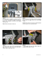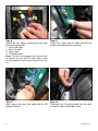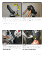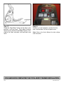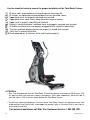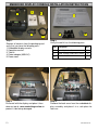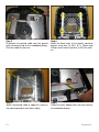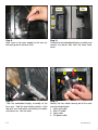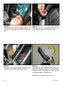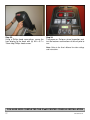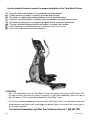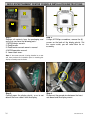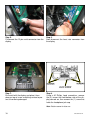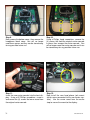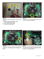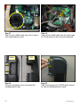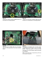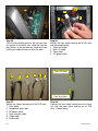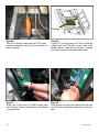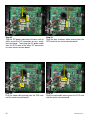
1
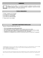
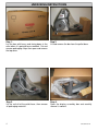
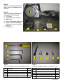
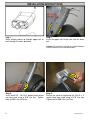
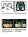
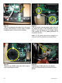
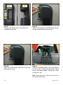
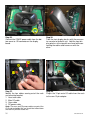
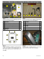
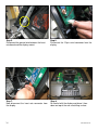
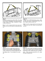
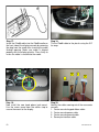
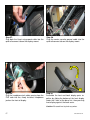
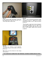
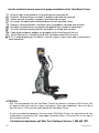
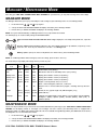
STAR TRAC
14410 Myford Road
Irvine, CA 926060 USA
WORK INSTRUCTIONS,
E-TBT / E-TBTe INSTALLATION
2
620-7921 Rev A
GENERAL
Before using this product, it is essential to read ALL installation Instructions and this
ENTIRE operations manual; the manual describes equipment setup and instructs
members on how to use it correctly and safely.
TOOLS REQUIRED
1. Phillips screwdriver, #2 (Included)
2. Hex (Allen) key, 3/16 (Included)
3. Hex (Allen) key, 16” (Included)
4. Hex (Allen) key, 5MM (Included)
5. Torque wrench (not included)
FACTORY CERTIFIED INSTALLER
If you are a Factory Certified Installer you must:
•
•
•
•
•
Adhere to all torque and assembly specifications.
Use a CALIBRATED TORQUE WRENCH with the necessary hex key sockets
NOT USE a powered drill, powered driver or powered impact tool for any part of the assembly.
Complete the assembly checklist is completed on each Star Trac product.
Complete the final programming, functional and cosmetic checklists for each Star Trac product.
Copyright 2008. Star Trac by Unisen, Inc. Star Trac Fitness, Star Trac®, and the Star Trac Logo are registered trademarks of Unisen Inc. All rights
reserved, including those to reproduce this book or parts thereof in any form without first obtaining written permission from Star Trac.
iPod® is a registered trademark of Apple, Inc.
MYE® is a registered trademark of MYE Entertainment LLC.
Every effort has been made to keep this information current; however, periodically, changes are made to the information herein, and these changes
will be incorporated into new editions of this publication. All product names and logos are trademarks of their respective owners. Printed in the USA.
3
620-7921 Rev A
UNPACKING INSTRUCTIONS
Step 1.
Lay the box with heavy end facing down in the
area where it is going to be assembled. Cut and
remove packaging straps then open and remove
the top cover.
Step 2.
Lift and remove the box from the pallet base.
Step 3.
Lift the unit off of the pallet base, then remove
all packaging materials.
Step 4.
Open the display assembly box and carefully
remove its content.
4
620-7921 Rev A
Step 5.
Remove remaining packaging materials and lay all components on
the floor.
1
Step 6.
Verify the following components
are included in the package:
1. TBT frame.
2. Display console assembly.
3. Upper neck.
4. Left and right upper body arms.
5. Owner’s manual, installation
manual and warranty registration card.
6. Hardware kit.
5
2
6
4
3
1
2
3
1
2
3
4
5
4
Step 7.
Verify the following tools are included in the kit:
Item Description
5
QTY
1
#2 Phillips screwdriver
1
2
3/16 Hex (Allen) key
1
3
5/16” Hex (Allen) key
1
4
5mm Hex (Allen) key
1
Step 8.
Verify the following hardware is included in the kit:
Item Description
1 6mm x 50mm socket head cap screw
QTY
4
2
5/16 - 18 x 3/4 button head screw
2
3
4
1/4 - 20 x 1/2 socket head screw
M4 x 0.7 x 19mm Philips head screw
10
6
5
Washer
4
620-7921 Rev A
INSTALLATION INSTRUCTIONS
Step 1.
Route display cables up through upper half of
neck through the holes provided.
Step 2.
Insert the upper half of the neck into the lower
half.
Caution: Be careful not to pinch any cables between
the two sections of the assembled neck.
Step 3.
Install two 5/16” - 18 X 3/4” button head screws
into front neck using a 3/16” hex key. Tighten
bolts to 200 in-lbs (23 N-m).
6
Step 4.
Secure the neck by tightening the 3/8-16 x 2”
socket head cap screw using a 5/16” hex key.
Tighten bolt to 300 in-lbs (34 N-m).
620-7921 Rev A
Step 5.
Using provided screwdriver, remove the M4 x
0.7 screws that hold the display assembly together, then separate the back of the display
from the front.
Note: Retain the screws for later use.
Step 7.
Line up the four holes of the mounting bracket
with holes of the neck, then insert four 6mm x
50mm socket head cap screws.
7
Step 6.
Slide the back of the display with the mounting
bracket onto the upper neck of the Total Body
Trainer.
Caution: Be careful not to pinch any cables between
the two sections of the assembled neck
Step 8.
Using provided 5mm hex key, tighten down the
screws to 240 in-lbs (27 N-m).
620-7921 Rev A
3
2
1
4
Step 9.
Identify the four cables coming out of the neck
and mounting bracket:
1. Heart rate cable
2. Main I/O cable
3. Coax cable
4. DC power cable
Step 10.
Plug-in the 12-pin main I/O cable into the front
display circuit board at J4 connector.
Note: If the unit is not equipped with Personal Viewing Screen, the coax and DC power cables should
be tucked down the neck as they are part of the PVS
Kit.
Step 11.
Next, plug-in the heart rate cable into the HR
board connector.
8
Step 12.
Plug back the HR ground cable into the quick
disconnect tab on the display frame.
620-7921 Rev A
2
1
Step 13.
Assemble the front and back display parts together by sliding the bottom of the front display
under the 2 tabs at the base first, then pressing
front display against the back cover.
Step 14.
Using provided Phillips head screw driver, secure the front display to the back with (8) M4 x
0.7 x 19mm long Phillips head screws.
Caution: Be careful not to pinch any wires.
Step 15.
Locate left side upper body arm, move to left
side of the Total Body Trainer. Attach the left
upper body arm to the left hub, align the pin to
the unthreaded hole.
9
Step 16.
Install the left arm and secure with (5) 1/4-20 x
1/2 socket head screws. Tighten the screws to
240 in-lbs (27 N-m) of torque with the 3/16” hex
key. Repeat for the opposite side.
620-7921 Rev A
Step 17.
Place the Total Body Trainer on the floor in the
position it will be used. Then adjust leveling
feet to assure that the Total Body Trainer is leveled to the floor and does not rock back and
forth.
Step 18.
Perform a visual inspection, and test the features and functions of the unit prior to use.
Note: Refer to the User’s Manual for other settings
and instructions.
YOU
HAVE
NOW
COMPLETED
THE INSTALLATION
OF YOUR
TOTAL
BODY TRAINER
YOU
HAVE
NOW
COMPLETED
THE TOTAL BODY
TRAINER
INSTALLATION
10
620-7921 Rev A
Use the checklist below to ensure the proper installation of the Total Body Trainer:
1. All parts, tools and hardware in the package are accounted for.
2. All screws are tightened and torqued down to their specified values.
3. Upper body arms are properly mounted and secured.
4. Upper body arms move freely, along the entire range of motion.
5. Upper neck is properly mounted and secured.
6. Display’s mounting bracket and back cover are properly mounted and secured.
7. All cables and harnesses are properly plugged to their respective connectors.
8. The front and back display plastics are properly installed and secured.
9. Verify unit is leveled to the floor.
10.Once powered up, all features of the unit function properly.
ATTENTION
• Star Trac recommends that the Total Body Trainers be spaced a minimum of 20.0 inches (0.5
m) apart to allow safe and easy ingress and egress. Even more importantly, there must be at
least 48 inches (1.25 m) of free space behind the Total Body Trainer.
•
As with any motorized equipment, the area where Total Body Trainers are located must be free
of obstructions and fixtures with sharp edges to prevent injury in the event that a user trips or
loses balance and falls.
For technical assistance call Star Trac Customer Service: 1 800 503 1221
11
620-7921 Rev A
EMBEDDED DISPLAY CONSOLE INSTALLATION INSTRUCTIONS
1
2
3
1
2
4
3
5
Step 1.
Remove all contents from the packaging and
verify that you have the following parts:
1. Embedded display console.
2. Operation manual.
3. Tool kit.
4. Power adaptor (60W AC).
5. Power cord.
Step 2.
Verify the tool kit has the following parts:
Step 3.
Be careful with the display and place it face
down on top of a non-scratching surface to
protect it from being damaged.
Step 4.
Remove the back cover from the embedded display assembly and place it in a safe place for
later use.
12
Item Description
QTY
1
Assembly instructions
1
2
Screw, Phillips Head, M4 x 19mm
18
3
Washer, flat, M4
5
620-7921 Rev A
Step 5.
Disconnect the ground cable from the ground
quick disconnect tab on the embedded display.
Save the cable for later use.
Step 6.
Mount the back cover to the display mounting
bracket using four (4) M4 x 0.7 x 19mm long
Phillips head screws and four (4) M4 flat washers.
Step 7.
Attach the ground cable to upper left screw on
the mounting bracket and secure tightly.
Step 8.
Pullout the coax adapter from the tuner card on
the embedded display.
13
620-7921 Rev A
After
Before
Step 9.
Now screw in the coax adaptor to the coax cable coming out of the base neck.
Step 10.
Go back to the embedded display assembly and
remove the plastic tabs from the lower back
cover.
3
2
1
Step 11.
Take the embedded display assembly to the
base unit. Hold the front display plastics at the
top with one hand while connecting the cables
and harnesses with the other.
14
4
Step 12.
Identify the four cables coming out of the neck
and mounting bracket:
1. Heart rate cable
2. Main I/O cable
3. Coax cable
4. DC power cable
620-7921 Rev A
Step 13.
Plug-in the heart rate cable from the neck into
the heart rate board connector on the FitCPU
board of the embedded display assembly.
Step 14.
Plug-in the 12-pin main I/O cable from the neck
to the 12 pin connector on the FitCPU board of
the embedded display assembly.
Step 15.
Next plug in the coax cable to the coax adapter
on the tuner card of the embedded display assembly.
Step 16.
Now plug in the DC power cable from the base
neck to DC connectors on the embedded display assembly.
15
620-7921 Rev A
Step 17.
Plug in the Heart rate ground cable into the
quick disconnect tab on the display mount.
Step 18.
Plug in the ground cable coming from upper left
side of the display mounting bracket into the
quick disconnect tab on the embedded display
assembly.
2
1
Step 19.
Assemble the front and back display parts together by sliding the bottom of the front display
under the 2 tabs at the base first, then pressing
front display against the back cover.
Step 20.
Using a Phillips head screw driver, secure the
front display to the back with (8) M4 x 0.7 x
19mm long Phillips head screws.
Caution: Be careful not to pinch any wires.
16
620-7921 Rev A
Step 21.
Now it is time to connect entertainment cable
and power to the unit. Connect the in-house
entertainment cable to the RF input at the base
of the unit.
Take the power supply from the kit and plug the
small barrel connector to the DC input. Then
take the power adapter cable from the kit and
plug it into the power supply and the electrical
receptacle.
Step 22.
Turn power on. Perform a visual inspection,
and test the features and functions of the unit
prior to use.
Note: Refer to the User’s Manual for other settings
and instructions.
YOU HAVE NOW COMPLETED THE EMBEDDED DISPLAY INSTALLATION
17
620-7921 Rev A
Use the checklist below to ensure the proper installation of the Total Body Trainer:
1.
2.
3.
4.
5.
6.
7.
8.
All parts and hardware in the package are accounted for.
Embedded display assembly is clear of any scratches or damage.
All screws are tightened and torqued down to their specified values.
Display’s mounting bracket and back cover are properly mounted and secured.
All cables and harnesses are properly plugged to their respective connectors.
The front and back display plastics are properly installed and secured.
Cable feed and power adaptor are plugged into the front base of the unit.
Verify unit is leveled to the floor.
9. Touch screen responds to commands as specified in the User’s Manual section regarding the
Calibration and Setup.
10. iPod test: Verify iPod menu is functioning and user can browse and listen to music
11. TV is setup properly per the owner’s manual, signal is clear and audio is coming from both earphones.
ATTENTION
• Star Trac recommends that the Total Body Trainers be spaced a minimum of 20.0 inches (0.5
m) apart to allow safe and easy ingress and egress. Even more importantly, there must be at
least 48 inches (1.25 m) of free space behind the Total Body Trainer.
•
As with any motorized equipment, the area where Total Body Trainers are located must be free
of obstructions and fixtures with sharp edges to prevent injury in the event that a user trips or
loses balance and falls.
For technical assistance call Star Trac Customer Service: 1 800 503 1221
18
620-7921 Rev A
iPod® CENTER CONSOLE INSTALLATION INSTRUCTIONS
1
3
2
5
1
2
4
Step 1.
Remove all contents from the packaging and
verify that you have the following parts:
1. iPod® center console.
2. iPod® cradle.
3. Owner’s manual.
4. Cable kit.
5. Lower back cover.
Step 2.
Verify the cable kit has the following two parts:
1. Center console power cable.
2. Headphone jack and mount.
Note: If the center console is being installed on a new
unit, then perform this installation prior to mounting the
display assembly onto the frame.
Step 3.
Using a #2 Phillips screwdriver, remove the (8)
screws on the back of the display plastic. Set
the screws aside, you will need them for reassembly.
19
Step 4.
Carefully open the display plastic, so as to not
detach the inner cables from the display.
620-7921 Rev A
Step 5.
Disconnect the ground wire between the heart
rate board and the display mount.
Step 6.
Disconnect the 12-pin serial connector from the
display
Step 7.
Now disconnect the heart rate connector from
the display
Step 8.
Be careful with the display and place it face
down on top of a non-scratching surface to protect it from being damaged.
20
620-7921 Rev A
Step 9.
Using a #2 Phillips head screwdriver, remove
the (4) screws that hold bottom side of the display console on, then remove the (1) screw that
holds the headphone jack cap.
Step 10.
Next remove the bottom cover, then remove the
headphone blank cover. You will no longer
need those covers and they can be stored away
for any possible future use.
Note: Retain screws for later use.
Step 11.
Using a Phillips head screwdriver, remove the
(4) screws that hold the original center console
in place, then remove the center console. You
will no longer need the center console and it can
be stored away for any possible future use.
21
Step 12.
Insert the new center console into the front display. Using a #2 Phillips screwdriver, screw in
and secure the (4) screws that were saved from
the original center console.
620-7921 Rev A
2
1
3
4
Step 13.
Now install the new head phone jack mount.
Use the screw saved from the earlier step to secure the mount to the display.
Step 14.
Identify the cables coming out of the new center
console:
1. Center console keypad ribbon cable.
2. Headphone jack cable.
3. Center console ground cable.
4. Seven-pin interface cable.
Step 15.
Connect the center console keypad cable to J8
connector on the display board.
Step 16.
Connect the seven-pin interface cable from the
console to J14 connector on the display board.
22
620-7921 Rev A
Step 17.
Take the headphone jack cable from the center
console and connect it to the newly installed
headphone jack in the front of the display.
Step 18.
Take the center console power cable from the
kit, attach the male 12 pin connector to the female 12 pin connector on the display board.
Then connect the (2) DC power connectors to
the center console.
Note: The DC power cables can be plugged to either one of the DC connectors on center console.
Step 19.
Take the new iPod® cradle from the kit and install it onto display console.
23
Step 20.
Now connect iPod® cable from the bottom
cover to J10 connector on the center console
board.
620-7921 Rev A
Before
After
Step 21.
Take the new bottom cover and remove the
handlebar plastic tabs.
Step 22.
Slide off and remove the CSAFE power connector from the old bottom plastic cover.
Step 23.
Install the CSAFE power connector on the new
bottom plastic cover.
Step 24.
Install the new bottom plastic cover onto display,
use the screws saved from the earlier step to
secure the display bottom. Tighten the screws
so they are snug.
Note: Take special care to not pinch any of the cables between the plastics.
24
620-7921 Rev A
Step 25.
Connect the CSAFE power cable from the bottom cover to J10 connector on the display
board.
Step 26.
Take the front display plastics with the new center console to the base unit. Hold the front display plastics at the top with one hand while connecting the cables and harnesses with the
other.
3
2
1
4
Step 27.
Identify the four cables coming out of the neck
and mounting bracket:
1. Heart rate cable
2. Main I/O cable
3. Coax cable
4. DC power cable
Step 28.
Plug-in the 12-pin main I/O cable from the neck
to the new 12 pin adaptor.
Note: The coax and DC power cables are part of the
PVS and embedded kits and should be tucked down
the neck for possible future use.
25
620-7921 Rev A
Step 29.
Next, plug-in the heart rate cable from the neck
into the heart rate board connector on the display.
Step 30.
Plug back the Heart rate ground cable into the
quick disconnect tab on the display mount.
2
1
Step 31.
Plug the center console ground cable into the
quick disconnect tab on the display mount.
Step 32.
Assemble the front and back display parts together by sliding the bottom of the front display
under the 2 tabs at the base first, then pressing
front display against the back cover.
Caution: Be careful not to pinch any wires.
26
620-7921 Rev A
Step 33.
Using a Phillips head screw driver, secure the
front display to the back with (8) M4 x 0.7 x
19mm long Phillips head screws.
Step 34.
Turn power on. Perform a visual inspection, and
test the features and functions of the unit prior to
use.
Note: Refer to the User’s Manual for other settings
and instructions.
YOU HAVE NOW COMPLETED THE iPod® CENTER CONSOLE INSTALLATION
27
620-7921 Rev A
Use the checklist below to ensure the proper installation of the Total Body Trainer:
1.
2.
3.
4.
5.
6.
7.
All parts, tools and hardware in the package are accounted for.
Center console assembly is properly mounted and secured.
All screws are tightened and torqued down to their specified values.
Display’s mounting bracket and back cover are properly mounted and secured.
All cables and harnesses are properly plugged to their respective connectors.
The front and back display plastics are properly installed and secured.
Verify iPod menu is functioning and user can browse and listen to music.
8. Verify clear audio coming from both earphones.
ATTENTION
• Star Trac recommends that the Total Body Trainers be spaced a minimum of 20.0 inches (0.5
m) apart to allow safe and easy ingress and egress. Even more importantly, there must be at
least 48 inches (1.25 m) of free space behind the Total Body Trainer.
•
As with any motorized equipment, the area where Total Body Trainers are located must be free
of obstructions and fixtures with sharp edges to prevent injury in the event that a user trips or
loses balance and falls.
For technical assistance call Star Trac Customer Service: 1 800 503 1221
28
620-7921 Rev A
MYE® ENTERTAINMENT CENTER CONSOLE INSTALLATION INSTRUCTIONS
1
3
2
4
5
Step 1.
Remove all contents from the packaging and
verify that you have the following parts:
1. MYE® center console.
2. iPod® cradle.
3. iPod® center console owner’s manual.
4. MYE® operation manual.
5. Lower back cover.
Step 2.
Using a #2 Phillips screwdriver, remove the (8)
screws on the back of the display plastic. Set
the screws aside, you will need them for reassembly.
Note: If the center console is being installed on a new
unit, then perform this installation prior to mounting the
display assembly onto the frame.
Step 3.
Carefully open the display plastic, so as to not
detach the inner cables from the display.
29
Step 4.
Disconnect the ground wire between the heart
rate board and the display mount.
620-7921 Rev A
Step 5.
Disconnect the 12-pin serial connector from the
display
Step 6.
Now disconnect the heart rate connector from
the display
Step 7.
Be careful with the display and place it face
down on top of a non-scratching surface to protect it from being damaged.
Step 8.
Using a #2 Phillips head screwdriver, remove
the (4) screws that hold bottom side of the display console on, then remove the (1) screw that
holds the headphone jack cap.
Note: Retain screws for later use.
30
620-7921 Rev A
Step 9.
Next remove the bottom cover, then remove the
headphone blank cover. You will no longer
need those covers and they can be stored away
for any possible future use.
Step 10.
Using a Phillips head screwdriver, remove the
(4) screws that hold the original center console
in place, then remove the center console. You
will no longer need the center console and it can
be stored away for any possible future use.
Step 11.
Insert the new center console into the front display. Using a #2 Phillips screwdriver, screw in
and secure the (4) screws that were saved from
the original center console.
Step 12.
Now install the new head phone jack mount
(which came connected to the new center console). Use the screw saved from the earlier
step to secure the mount to the display.
31
620-7921 Rev A
2
1
3
4
Step 13.
Identify the cables coming out of the new center
console:
1. Center console keypad ribbon cable.
2. Center console power cable
3. Center console ground cable.
4. Seven-pin interface cable.
Step 14.
Connect the center console keypad cable to J8
connector on the display board.
Step 15.
Connect the seven-pin interface cable from the
console to J14 connector on the display PC
board.
Step 16.
Take the center console power cable and attach
the male 12 pin connector to the female 12 pin
connector on the display board.
32
620-7921 Rev A
Step 17.
Take the new iPod® cradle from the kit and install it onto display console.
Before
After
Step 19.
Take the new bottom cover and remove the
handlebar plastic tabs.
33
Step 18.
Now connect iPod® cable from the iPod cradle
to J10 connector on the center console board.
Step 20.
Slide off and remove the CSAFE power connector from the old bottom plastic cover.
620-7921 Rev A
Step 21.
Install the CSAFE power connector on the new
bottom plastic cover.
Step 22.
Install the new bottom plastic cover onto display,
use the screws saved from the earlier step to
secure the display bottom. Tighten the screws
so they are snug, then plug in the CSAFE power
cable to the back of the display.
Note: Take special care to not pinch any of the cables between the plastics.
3
2
1
Step 23.
Take the front display plastics with the new center console to the base unit. Hold the front display plastics at the top with one hand while connecting the cables/harnesses with the other.
4
Step 24.
Identify the four cables coming out of the neck
and mounting bracket:
1. Heart rate cable.
2. Main I/O cable.
3. Coax cable.
4. DC power cable.
Note: The coax and DC power cables are part of
the PVS and embedded kits and should be tucked
down the neck for possible future use.
34
620-7921 Rev A
Step 25.
Plug-in the 12-pin main I/O cable from the neck
to the new 12 pin adaptor.
Step 26.
Next, plug-in the heart rate cable from the neck
into the heart rate board connector on the display.
Step 27.
Plug back the Heart rate ground cable into the
quick disconnect tab on the display mount.
Step 28.
Plug the center console ground cable into the
quick disconnect tab on the display mount.
35
620-7921 Rev A
2
1
Step 29.
Assemble the front and back display parts together by sliding the bottom of the front display
under the 2 tabs at the base first, then pressing
front display against the back cover.
Step 30.
Using a Phillips head screw driver, secure the
front display to the back with (8) M4 x 0.7 x
19mm long Phillips head screws.
Caution: Be careful not to pinch any wires.
Step 31.
Turn power on. Perform a visual inspection, and
test the features and functions of the unit prior to
use.
Note: Refer to the User’s Manual for other settings
and instructions.
YOU HAVE NOW COMPLETED THE MYE® CENTER CONSOLE INSTALLATION
36
620-7921 Rev A
Use the checklist below to ensure the proper installation of the Total Body Trainer:
1.
2.
3.
4.
5.
6.
7.
8.
All parts, tools and hardware in the package are accounted for.
Center console assembly is properly mounted and secured.
All screws are tightened and torqued down to their specified values.
Display’s mounting bracket and back cover are properly mounted and secured.
All cables and harnesses are properly plugged to their respective connectors.
The front and back display plastics are properly installed and secured.
Verify MYE center console function as specified in the user manual.
iPod test: Verify iPod menu is functioning and user can browse and listen to music.
ATTENTION
• Star Trac recommends that the Total Body Trainers be spaced a minimum of 20.0 inches (0.5
m) apart to allow safe and easy ingress and egress. Even more importantly, there must be at
least 48 inches (1.25 m) of free space behind the Total Body Trainer.
•
As with any motorized equipment, the area where Total Body Trainers are located must be free
of obstructions and fixtures with sharp edges to prevent injury in the event that a user trips or
loses balance and falls.
For technical assistance call Star Trac Customer Service: 1 800 503 1221
37
620-7921 Rev A
PERSONAL VIEWING SCREEN (PVS) INSTALLATION INSTRUCTIONS
2
1
1
4
3
2
5
6
3
4
5
6
7
7
Step 1.
Step 2.
Remove all contents from the packaging and verify
that you have the following parts:
Remove all content from the hardware kit packaging
and verify that you have the following parts:
Item
1
2
3
4
5
6
7
Description
PVS assembly with mounting bracket.
Headphone jack and mount.
PVS center console.
Owner’s manual with registration card.
Power adaptor.
Hardware kit.
Power cord.
QTY
1
1
1
1
1
1
1
Step 3.
Using a #2 Phillips screwdriver, remove the (8)
screws on the back of the display plastic. Set
the screws aside, you will need them for reassembly.
38
Item Description
1
2
3
4
5
6
7
5” tape
3.5” tie strap
5” tie strap
M4 screws
M8 button head screws
5mm Hex hex
iPod® cable
QTY
1
1
1
4
4
1
1
Step 4.
Carefully open the display plastic, so as to not
detach the inner cables from the display.
620-7921 Rev A
Step 5.
Disconnect the ground wire between the heart
rate board and the display mount.
Step 6.
Disconnect the 12-pin serial connector from the
display.
Step 7.
Now disconnect the heart rate connector from
the display.
Step 8.
Be careful with the display and place it face
down on top of the non-scratching surface.
39
620-7921 Rev A
Screws
Screws
Step 9.
Remove the cap cover with the Star Trac logo
from the back cover plastics by removing the (2)
screws using a #2 Phillips screwdriver. Retain
screws for later use.
Note: You will no longer need the cap cover and, if
desired, you can store it away for any possible future
use.
Step 11.
Mount the PVS assembly on the mounting
bracket, then thread the (4) M8 buttonhead
screws through the PVS mounting bracket into
the display mount. Do not tighten the screws
yet.
40
Step 10.
Remove the (2) M8 buttonhead screws retaining the cross-brace using provided 5mm Hex
key. Retain screws for later use.
Note: You will no longer need the cross-brace and,
if desired, you can store it away for any possible future use.
Step 12.
Adjust the new cap with the grommet into place.
Then use the 5mm Hex key to secure the M8
buttonhead screws holding the PVS assembly in
place. Now secure the cap with the (2) screws
that were saved earlier.
620-7921 Rev A
Step 13.
Using a #2 Phillips head screwdriver, remove
the (4) screws that hold the bottom cover of the
display console, then remove the (1) screw that
holds the headphone jack cap.
Note: Retain screws for later use.
Step 15.
Using a Phillips head screwdriver, remove the
(4) screws that hold the original center console
in place, then remove the center console.
Step 14.
Next remove the bottom cover, then remove the
headphone blank cover.
Note: You will no longer need the headphone jack
cover and it can be stored away for any possible
future use.
Step 16.
Insert the new center console into the front display. Using a #2 Phillips screwdriver, screw in
and secure the (4) screws that were saved from
the original center console.
Note: You will no longer need the center console
and it can be stored away for any possible future
use.
41
620-7921 Rev A
Step 17.
Install the iPod® cable into the iPod® cradle on
the front side of the display console by removing
the plug from the cradle then inserting the cable
through opening. Make sure cable is aligned
properly with the display plastics. Press firmly to
insure the cable is seated into the cradel.
Step 18.
Tie the iPod® cable to the plastic using the 3.5”
tie wrap.
2
1
Step 19.
Now install the new head phone jack mount.
Use the screw saved from the earlier step to
secure the mount to the display.
42
3
4
Step 20.
Identify the cables coming out of the new center
console:
1. Center console keypad ribbon cable.
2. Center console power cable.
3. Center console ground cable.
4. Seven-pin interface cable.
620-7921 Rev A
Step 21.
Connect the center console keypad cable to J8
connector on the display board.
Step 22.
Connect the seven-pin interface cable from the
console to J14 connector on the display board.
Step 23.
Now connect the iPod® cable from the bottom
cover to J10 connector on the center console
board.
Step 24.
Next replace the bottom cover. Use the screws
saved from the earlier step to secure the display
bottom. Tighten the screws so they are snug,
then plug in the CSAFE power cable to the back
of the display.
Note: Take special care to not pinch any of the cables between the plastics.
43
620-7921 Rev A
3
2
1
Step 25.
Take the front display plastics with the new center console to the base unit. Hold the front display plastics at the top with one hand while connecting the cables/harnesses with the other.
4
Step 26.
Identify the four cables coming out of the neck
and mounting bracket:
1. Heart rate cable
2. Main I/O cable
3. Coax cable
4. DC power cable
From PVS Neck
1
2
3
4
5
6
From Base Neck
Step 27.
Identify the cables coming out of the PVS neck:
1. Coax cable.
2. Headphone jack cable.
3. DC power cable
4. Data interface cable
5. Video cable
6. Audio cable
44
Step 28.
Connect the coax cable coming out of the base
unit with the coax cable coming out of PVS
neck. Secure tightly.
620-7921 Rev A
Tie Wrap
Step 29.
Take the 5” piece of tape from the PVS kit and
wrap the connectors so that all of the metal surface is covered.
Step 30.
Using a 5” tie wrap from the PVS kit, bind the
cables from the PVS neck to one side of the
display mount. Take the tie and put it through
the hole on one of the display mount tubes.
Step 31.
Plug-in the 12-pin main I/O cable coming from
the unit base into the front display circuit board
at J4 connector.
Step 32.
Next, plug-in the heart rate cable from the neck
into the heart rate board connector on the display.
45
620-7921 Rev A
Step 33.
Plug the DC power cable from the base neck to
either one of the DC connectors on new center
console board. Then plug the DC power cable
from the PVS neck to the other DC connectors
on same center console board.
Step 34.
Plug the data interface cable coming from the
PVS neck into the center console board.
Step 35.
Plug the video cable coming from the PVS neck
into the center console board.
Step 36.
Plug the audio cable coming from the PVS neck
into the center console board.
46
620-7921 Rev A
Step 37.
Plug back the Heart rate ground cable into the
quick disconnect tab on the display mount.
Step 38.
Plug the center console ground cable into the
quick disconnect tab on the display mount.
2
1
Step 39.
Plug the headphone jack cable coming from the
PVS neck into the, newly installed, headphone
jack on the front of display.
Step 40.
Assemble the front and back display parts together by sliding the bottom of the front display
under the 2 tabs at the base first, then pressing
front display against the back cover.
Caution: Be careful not to pinch any wires.
47
620-7921 Rev A
Step 41.
Using a Phillips head screw driver, secure the
front display to the back with (8) M4 x 0.7 x
19mm long Phillips head screws.
Step 42.
Now it is time to connect entertainment cable
and power to the unit. Connect the in-house
entertainment cable to the RF input at the base
of the unit.
Take the power supply from the kit and plug the
small barrel connector to the DC input. Then
take the power adapter cable from the kit and
plug it into the power supply and the electrical
receptacle.
Step 43.
Turn power on. Perform a visual inspection,
and test the features and functions of the unit
prior to use.
Note: Refer to the User’s Manual for other settings
and instructions.
YOU HAVE NOW COMPLETED THE PERSONAL VIEWING SCREEN INSTALLATION
48
620-7921 Rev A
Use the checklist below to ensure the proper installation of the Total Body Trainer:
1. All parts, tools and hardware in the package are accounted for.
2. Personal Viewing Screen assembly is properly mounted and secured.
3. Center console assembly is properly mounted and secured.
4. All screws are tightened and torqued down to their specified values.
5. Display’s mounting bracket and back cover are properly mounted and secured.
6. All cables and harnesses are properly plugged to their respective connectors.
7. The front and back display plastics are properly installed and secured.
8. Cable feed and power adaptor are plugged into the front base of the unit.
9. Verify iPod menu is functioning and user can browse and listen to music
10. TV is setup properly per the owner’s manual, signal is clear and audio is coming from
both earphones.
ATTENTION
• Star Trac recommends that the Total Body Trainers be spaced a minimum of 20.0 inches (0.5
m) apart to allow safe and easy ingress and egress. Even more importantly, there must be at
least 48 inches (1.25 m) of free space behind the Total Body Trainer.
•
As with any motorized equipment, the area where Total Body Trainers are located must be free
of obstructions and fixtures with sharp edges to prevent injury in the event that a user trips or
loses balance and falls.
For technical assistance call Star Trac Customer Service: 1 800 503 1221
49
620-7921 Rev A
STAR TRAC
14410 Myford Road
Irvine, California 92606
Telephone: (800) 228-6635, (714) 669-1660
Fax: (714) 508-3303
http://www.startrac.com
50
620-7921 Rev A
Star Trac Fitness
TM
E-TBT Total Body Trainer
OWNER’S MANUAL
MANAGER / MAINTENANCE MODE
After using your STAR TRAC E SERIES TOTAL BODY TRAINERS for a period of time, you may wish to change some of its settings.
MANAGER MODE
The Manager Mode allow you to query and modify the basic settings of your Total Body Trainer. To enter Manager Mode:
1. Press and hold the
,
and
keys together.
2. A beep will sound and “MANAGER MODE” will display momentarily in the Message Window.
3. Release all keys. “SERIAL NO #####” will display in the Message Window.
NOTE: The system will automatically exit Manager Mode if no key is pressed for 30 seconds.
The following keys are used to modify settings in MANAGER MODE:
Upper and Lower Data Information Window SCROLL Keys: Display the next and previous parameters, respectively.
Increase and Decrease LEVEL Keys: Adjust the value of the displayed parameter up and down, respectively, in increments of 1 unit . These keys do not save the new value - see OK Key below.
OK Key: Updates (saves) the values of all parameters in Flash memory, and exits Manager Mode.
NOTE: To exit Manager Mode without saving any values or settings, press the QUICK START key.
The items that you may display and change with the previous keys are:
Item
Serial No
Lowest
Value
Highest
Value
Default
Value
Meaning
0
65535
0
Date
01/00
12/99
01/05
Display Vers 1
01.00
99.99
N/A
Display panel software version (set by factory)
Display Vers 2
01.00
99.99
N/A
Display panel software version (set by factory)
LCB Vers
01.00
99.99
N/A
Display panel software version (set by factory)
English
Metric
English
English = units of pounds, miles, feet, inches;
Units
Serial number (set by factory)
Manufacture date for the Total Body Trainer (set by factory)
Metric = units of kilograms, kilometers, centimeters.
Time
Weight
Language
5
99
99
Maximum time in minutes allowed for program, excluding warm-up and cooldown.
50 (Lb)
350 (Lb)
350 lbs
22 (KG)
158 (KG)
158 (KG)
N/A
N/A
ENGL
Default (to user), typical weight in lb (UNITS=English), or kg
(UNITS=Metric).
Language is English (ENGL), Dutch (DUTC), French (FREN), German (GERM),
Portuguese (PORT), Spanish (SPAN), Swedish (SWED), Italian (ITAL) or
Katakana (KATA).
MAINTENANCE MODE
Your Service Representative may need to check accumulated data about the past usage of your STAR TRAC E SERIES TOTAL BODY
TRAINER, test its display controls, or investigate error messages. For these reasons, your Total Body Trainer is equipped with a
Maintenance Mode. The Maintenance Mode includes all of the items available through Manager Mode, plus additional items for Service
and Diagnostic use. To enter Maintenance Mode:
1. Press and hold the
,
and
keys together.
2. A beep will sound and “MAINTENANCE MODE” will display momentarily in the Message Window.
3. Release all keys. “SERIAL NO #####” will display in the Message Window.
STAR TRAC E SERIES TOTAL BODY TRAINERS OWNER’S MANUAL
25
The following keys are available in MAINTENANCE MODE:
Upper and Lower Data Information Window SCROLL Keys: Display the next and previous parameters, respectively. Keys will repeat if held.
Increase and Decrease LEVEL Keys: Adjust the value of the displayed parameter up and down, respectively, in increments of 1 unit . These keys do not save the new value - see OK Key below.
OK Key: Updates (saves) the values of all parameters in Flash memory, and exits Maintenance Mode.
NOTE: To exit Maintenance Mode without saving any values or settings, press the QUICK START key.
The items that you may display and change with the previous keys are:
Lowest
Value
Highest
Value
Default
Value
0
65535
0
Date
01/00
12/99
01/05
Display Vers 1
01.00
99.99
N/A
Display panel software version (set by factory)
Display Vers 2
01.00
99.99
N/A
Display panel software version (set by factory)
LCB Vers
01.00
99.99
N/A
Load Control Board software version (set by factory)
Units
English
Metric
English
English = units of pounds, miles, feet, inches;
Metric = units of kilograms, kilometers, centimeters.
Time
5
99
99
50 (Lb)
22 (KG)
350 (Lb)
158 (KG)
350 lbs
158 (KG)
Language
N/A
N/A
ENGL
Language is English (ENGL), Dutch (DUTC), French (FREN), German (GERM),
Portuguese (PORT), Spanish (SPAN), Swedish (SWED), Italian (ITAL) or
Katakana (KATA).
Model
N/A
N/A
PB-UB
E-UB = E SERIES - Upright
E-RB = E SERIES - Recumbent
E-TBT = E SERIES TOTAL BODY TRAINER
STEPPER = Pro Stepper
LCB TYPE
N/A
N/A
VERI
Type of LCB detected by display.
CSAFE
N/A
N/A
OFF
Turns on/off CSAFE functionality.
PVS
N/A
N/A
ATSC
ATSC/NTSC or PAL/SECAM, RF signal.
Wall Power
N/A
N/A
OFF
Turns the wall power setting on/off.
AUTO FAN
OFF
ON
ON
Turns fan on 1 minute into the program.
OPER Hours
0
65535
0
Total operating hours.
Quick Start
0
65535
0
Number of times the Quick Start program was run since last reset.
Manual
0
65535
0
Number of times the Manual Program was run since last reset.
TB Begin
0
65335
0
Number of times the Total Body - Beginner program was run since last reset.
TB Inter
0
65335
0
Number of times the Total Body - Intermediate program was run since last reset.
TB Diff
0
65335
0
Number of times the Total Body - Difficult program was run since last reset.
Auto Pilot
0
65535
0
Number of times the Auto Pilot Program was run since last reset.
IHR Prog
0
65535
0
Number of times the Interval Heart Rate Control Program was run since last
reset.
CHR Prog
0
65535
0
Number of times the Constant Heart Rate Control Program was run since last
reset.
Item
Serial No
Weight
26
Meaning
Serial number (set by factory)
Manufacture date for the Total Body Trainer (set by factory)
Maximum time in minutes allowed for program, excluding warm-up and cooldown.
Default (to user), typical weight in lb (UNITS=English), or kg
(UNITS=Metric).
STAR TRAC E SERIES TOTAL BODY TRAINERS OWNER’S MANUAL
Lowest
Value
Highest
Value
Default
Value
CW Prog
0
65535
0
Number of times the Continuous Watts Program was run since last reset.
Alpine
0
65535
0
Number of times the Alpine Pass Program was run since last reset.
Rndm Prog
0
65535
0
Number of times the Random Hill Program was run since last reset.
UB Revs
0
65335
0
Number of times the upper body system completed a full revolution.
Comm Lost
0
65535
0
Number of times a “Communication Lost” condition occurred since last reset.
Key Down
0
65535
0
Number of times a “Key Down” condition occurred since last reset.
BATT LOW
0
65535
0
Number of times battery voltage measured between 5.3 and 5.7 volts.
REPL BATT
0
65535
0
Number of times battery voltage measured below 5.3 volts.
LED Test
N/A
N/A
N/A
Access to integral LED test function (for use by authorized Maintenance
Technician).
Keypad Test
N/A
N/A
N/A
Access to integral keypad test function (for use by authorized Maintenance
Technician).
Heart Rate
Test
N/A
N/A
N/A
Access to integral heart rate system test function (for use by authorized
Maintenance Technician).
FAN TEST
N/A
N/A
N/A
Access to integral FAN TEST function(for use by authorized Maintenance
Technician)
CSAFE TEST
N/A
N/A
N/A
Access to integral CSAFE TEST function (for use by authorized Maintenance
Technician)
Measurements
N/A
N/A
N/A
Access to integral Measurements function (for use by authorized Maintenance
Technician).
UB
CALIBRATION
N/A
N/A
N/A
Access to integral Upper Body system calibration function (for use by author
ized Maintenance Technician).
Item
Meaning
TROUBLESHOOTING
STAR TRAC E SERIES TOTAL BODY TRAINERS perform a self-test at the beginning of every workout. If a problem is detected, a
message displays before or after the workout, depending on the nature of the problem. Star Trac recommends that you refer your questions about your STAR TRAC E SERIES TOTAL BODY TRAINER operation and suspected malfunctions to Star Trac’s Service Hotline
at (800) 503-1221, or USA 1-714-669-1660.
SERVICE MESSAGES
The following messages are displayed if the associated problem is detected during self-test.
I
Key Down - One or more keys on the display panel are stuck in the “on” position. This can occur if a user presses keys before
the system is turned on, or if a key is held down for more than 10 seconds. Call Star Trac Product Support for assistance if the
Key Down message continues to display.
STAR TRAC E SERIES TOTAL BODY TRAINERS OWNER’S MANUAL
27