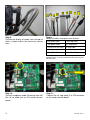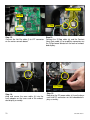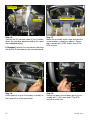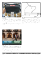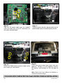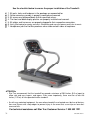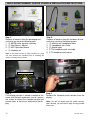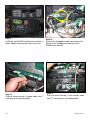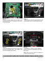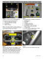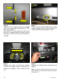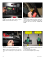
1
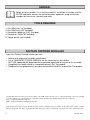
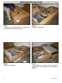
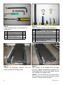
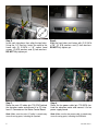
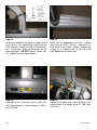
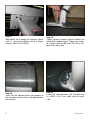
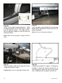
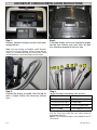
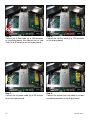
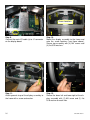
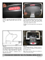
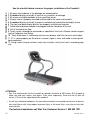
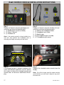
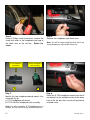
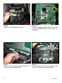
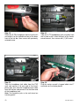
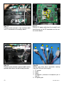
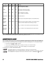
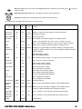
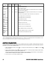
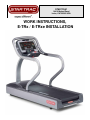
STAR TRAC
14410 Myford Road
Irvine, CA 926060 USA
WORK INSTRUCTIONS,
E-TRx / E-TRxe INSTALLATION
2
620-7920 Rev A
GENERAL
Before using this product, it is essential to read ALL installation Instructions and this
ENTIRE operations manual; the manual describes equipment setup and instructs
members on how to use it correctly and safely.
TOOLS REQUIRED
1. Hex (Allen) key, 1/4” (Included)
2. Hex (Allen) key, 5/32” (Included)
3. Screwdriver (blade-tip), 3/32” (Included)
4. Screwdriver, Philips, #2 (Included)
5. Torque wrench (not included)
FACTORY CERTIFIED INSTALLER
If you are a Factory Certified Installer you must:
•
•
•
•
•
Adhere to all torque and assembly specifications.
Use a CALIBRATED TORQUE WRENCH with the necessary hex key sockets
NOT USE a powered drill, powered driver or powered impact tool for any part of the assembly.
Complete the assembly checklist is completed on each Star Trac product.
Complete the final programming, functional and cosmetic checklists for each Star Trac product.
Copyright 2008. Star Trac by Unisen, Inc. Star Trac Fitness, Star Trac®, and the Star Trac Logo are registered trademarks of Unisen Inc. All rights
reserved, including those to reproduce this book or parts thereof in any form without first obtaining written permission from Star Trac.
iPod® is a registered trademark of Apple, Inc.
MYE® is a registered trademark of MYE Entertainment LLC.
Every effort has been made to keep this information current; however, periodically, changes are made to the information herein, and these changes
will be incorporated into new editions of this publication. All product names and logos are trademarks of their respective owners. Printed in the USA.
3
620-7920 Rev A
UNPACKING INSTRUCTIONS
Step 1.
Lay the unit in the area where it is going to be
assembled and remove the straps.
Step 2.
Remove the top cover.
Step 3.
Remove the side box.
Step 4.
Lay all boxes on the floor and verify that all
components are included (see next page for
details).
4
620-7920 Rev A
Step 5.
Verify the following components are included in
box one:
• Left handrail (p/n 020-7179).
• Right handrail (p/n 020-7181).
• Front neck assembly.
1
4
2
Step 6.
Verify the following components are included in
box two:
Top rail with electronic display assembly.
3
5
6
Step 7.
Verify components in box two (continued):
1.Neck cover.
2.Display console’s top back cover (p/n 020-7074).
3.Neck grommet.
4.Power cable.
Step 8.
Verify components in box two (continued):
•
•
Display console’s upper back cover (p/n 020-7069).
Display console’s lower back cover (p/n 020-7070).
5.Owner’s manual with warranty registration card.
6.Hardware kit.
5
620-7920 Rev A
1
2
7
6
3
4
1
Step 9.
Verify the following tools are included in the
hardware kit :
Item
1
2
3
4
Description
Hex (Allen) key, 1/4”
Hex (Allen) key, 5/32”
Screwdriver (blade-tip), 3/32”
Screwdriver, Phillips, #2
QTY
1
1
1
1
Step 11.
Remove the packaging materials from the
frame assembly with motor shroud.
2
3
4
5
Step 10.
Verify hardware included in the hardware kit:
Item
1
2
3
4
5
6
7
Description
QTY
Screw 5/16”-18x3.0”, Socket Head Cap
2
Screw 5/16”-18x1.0”, Socket Head Cap
12
Screw 1/4”-28 3/8”, Button Head Socket Cap 5
Screw #10-24 x 3/4, Truss Head,
7
Screw M4x.7, 19mm, Pan Head,
16
Washer, Flat, 5/16” I.D. x 1.2” O.D.
16
Washer, Split Lock, 5/16”
16
Step 12.
With a helper, lift the treadmill frame assembly
from the shipping crate platform and place it in
the location where it will be used. Make sure the
unit is placed near a power outlet.
Caution: The motor shroud end of the frame assembly is very heavy. It may require two people to lift this
end when moving the frame assembly.
6
620-7920 Rev A
INSTALLATION INSTRUCTIONS
Step 1.
Lift the front motor shroud off of the frame assembly.
Note: Make sure the shroud is properly stored to
prevent damage.
Step 3.
Position neck close to the service opening in
the front of treadmill so the cables go into the
opening first.
Step 2.
Remove the neck form shipping box and verify
the cables are properly fed through attached
protective tube in the base of the neck.
Note: The tube will protect cables from getting
pinched during installation and will make it easier to
route them through service opening.
Step 4.
Route all cables from neck into motor compartment through lower neck service opening.
Caution: Make sure not to pinch any cables.
7
620-7920 Rev A
Step 5.
Insert neck into place, then align the top holes.
Using the 1/4” Hex key, fasten the neck to the
frame with (2) 5/16-18 x 1.0” socket head
screws, (2) 5/16 washers and (2) lock washers.
DO NOT fully tighten yet.
Step 6.
Align the front holes and fasten with (2) 5/16-18
x 3.0”, (2) 5/16 washers and (2) lock washers.
DO NOT fully tighten yet.
Step 7.
Route the main I/O cable (p/n 715-3781) behind
the elevation motor and connect it to I/O interface J2 Connector on the Motor Control Board.
Step 8.
Route the fan power cable (p/n 715-3678) behind the elevation motor and connect it to fan
power supply board.
Note: Make sure the main I/O cable is routed away
from all moving parts, including the flywheel.
Note: Make sure the fan power cable is routed away
from all moving parts, including the RPM disk.
8
620-7920 Rev A
Step 9. (for E-TRxe model only)
Route the user detect cable behind the elevation motor and plug it into the user detect connector on the left side of frame.
Note: This user-detect cable is only available on the
E-TRxe model. If your unit is not equipped with an
embedded display; then skip this step.
Step 11.
Once the display frame is in place, fasten it to
the neck using the 1/4” Hex key with (2) 5/16-18
x 1.0” socket head screws, (2) 5/16 washers
and (2) lock washers. DO NOT fully tighten yet.
Step 10.
Now install the top display rail. Align the rail’s
mounting holes with the neck holes.
Note: If the electronic display console was assembled
to the rail; remove the screws holding it to the rail and
store the display for later use.
Hint: If one person is assembling the unit, insert two
5/16 screws into top rail holes and use them to align
and temporary hold the rail while you secure it from the
back.
Step 12.
Identify left and right handrails by the part number
affixed on the bottom of rails. (left rail’s part number
is 020-7179, and right rail’s part number is 0207181).
Assemble handrail joint as shown. DO NOT fasten
the (2) #10 button head socket screws in the upper
handrail joints until both handrails are in place.
9
620-7920 Rev A
Step 13.
Install left handrail to the frame as shown using
(3) 5/16-18 x 1.0” socket head screws and (3)
5/16 washers. Partially lift up the side bed covers, if necessary. Note the orientation of the
mounting plate. DO NOT tighten screws fully
yet. Repeat install for right handrail.
Step 14.
Make sure the gap between the rails is closed
and, using the 5/32” Hex key, fasten the (2)
#10 button head socket screws. Tighten the
screws to a a torque value of 45 in-lbs (5.0
Nm). Repeat for the other side.
Step 15.
Now tighten the 2 front neck screws (5/16-18 x
3.0” socket head) to a torque value of 200 inlbs (22.5 Nm).
Step 16.
Tighten the 2 upper neck screws (5/16-18 x 3.0”
socket head) to a torque value of 200 in-lbs
(22.5 Nm).
10
620-7920 Rev A
Step 17.
Now tighten the 4 display rail fasteners (where
neck is joined with display rail) to a torque
value of 200 in-lbs (22.5 Nm).
Step 18.
Tighten handrail fasteners where handrails are
joined with treadmill frame. Tighten the screws
to a torque value of 200 in-lbs (22.5 Nm). Repeat for the other side.
Step 19.
Verify that the side bed covers join properly to
the end caps and that there is no gap between
the two parts.
Step 20.
Fasten the side bed covers (left and right) with
(1) #10-24 x 3/4 Truss head screw on each
side.
11
620-7920 Rev A
Step 21.
Re-install the shroud over motor compartment.
Slide the back end of shroud in place (where
shroud meets rails) then align the screw holes
on the front of shroud with the holes on the
frame.
Step 22.
Secure the front of the motor shroud with (2)
#10 Truss head screws.
2
1
Step 23.
Now secure the sides of the motor shroud and
the bed covers to the frame with (4) #10 Truss
head screws.
12
Step 24.
Snap the front motor shroud cap in place, then
slide and install the neck grommet over the cap.
620-7920 Rev A
Step 25.
Install left and right handrail grommets. Slide
the grommet down the rail and snap it in place
over the bed rails covers. Push down and rotate the grommet slightly to seat the tabs into
the plastic covers.
Step 26.
Insert the power cord through the tie wrap loop
below motor compartment and connect it to the
power receptacle.
Note: Don’t turn on the power switch yet.
Note: Make sure the grommet is tightly secured in
place.
Step 27.
Secure the power cable to the frame with the tie
-strap and cut excess strap.
Caution: Make sure not to damage the power cord.
13
Step 28.
Position the treadmill in its place. If leveling the
treadmill is necessary, loosen the lock nuts of
the leveling feet, rotate the feet until the treadmill is stabilized, then re-tighten the lock nuts.
620-7920 Rev A
LED DISPLAY CONSOLE INSTALLATION INSTRUCTIONS
Step 1.
Remove electronic display console from packaging materials.
Step 2.
If the back display covers are attached to display
console then remove and save them for later
use, otherwise proceed to the next step.
Note: If you are installing an iPod® Kit, a MYE Entertainment kit or a Personal Viewing Screen kit along with this
display, it is recommended that you install the kit’s center
console before you mount the display onto the frame.
a
Step 3.
Position the display assembly near the top rail
while a helper makes the necessary connections.
b
c
d
e
f
g
i
j
h
Step 4.
Identify the cables coming from neck and rails:
a. DC power cable
f. Rail stop cable
b. Fan power cable
g. E-Stop cable
c. Contact heart rate cable
h. Coax cable
d. Headphone jack cable i. hot Bar keypad cable
e. Main I/O cable
j. User-Detect (E-TRxe only)
Note 1: If the unit is not equipped with a PVS or iPod® kit,
then the PVS power cable and coax cable should be
tucked down the neck.
Note 2: The User-Detect cable is only available on the ETRxe model.
14
620-7920 Rev A
Step 5.
Connect the E-Stop cable (g) to J25 connector
on the display board, then connect the rail stop
cable (f) to J5 connector on the display board.
.
Step 6.
Connect the Hot Bar cable (i) to J15 connector
on the display board.
Step 7.
Connect the fan power cable (b) to J20 connector on the display board.
Step 8.
Connect the contact heart rate cable (c) to heart
rate board connector on the display board.
15
620-7920 Rev A
Screw Locations
Step 9.
Connect the main I/O cable (e) to J1 connector
on the display board.
Step 10.
Mount the display assembly to the frame and
note the screw locations (see figure above).
Secure top assembly with (4) M4 screws and
(4) flat 5/16 washers.
Step 11.
Attach ground strap of the display assembly to
the frame with a screw and washer.
Step 12.
Secure the lower left and lower right of the display assembly with (1) M4 screw and (1) flat
5/16 washer on each side.
16
620-7920 Rev A
Step 13.
Install the top back cover piece (p/n 020-7074)
onto the upper display back cover (p/n 0207069).
Step 14.
Install the lower display back cover onto display using (6) M4 screws. Next install upper
display back cover onto display with (8) of the
same screws, tighten all screws.
Caution: Do not use power tools or over torque the
screws.
Step 15.
If not performed previously, position the treadmill where you plan to use it. If necessary, level
the treadmill using the two adjustable feet under
the tail roller. Loosen the lock nuts, rotate the
feet until the treadmill is stabilized, and retighten the lock nuts.
Step 16.
Turn the power switch on. Perform a visual inspection, and test the features and functions of
the unit prior to use.
Note: Refer to the User’s Manual for calibration instructions and other settings.
YOU HAVE NOW COMPLETED THE E-TRx TREADMILL INSTALLATION
17
620-7920 Rev A
Use the checklist below to ensure the proper installation of the E-Series Treadmill:
1. All parts and hardware in the package are accounted for.
2. All screws are tightened down to their specified values.
3. Neck is properly mounted and secured to the base frame.
4. Left and right handrails are properly mounted and secured to the based frame.
5. Display frame is properly mounted and secured to the neck and handrails.
6. Electronic display console is properly mounted and secured to the display frame.
7. All cables and harnesses are properly plugged to their respective connectors.
8. All cables inside the motor compartment are routed away from all moving parts.
9. Motor shroud and side bed covers are properly installed and secured.
10. Unit is leveled to the floor.
11. Using a chest strap or wireless heart rate simulator, verify heart rate is recording properly.
12. Once powered up, all features of the unit function properly.
ATTENTION
• Star Trac recommends that the treadmill be spaced a minimum of 20.0 inches (0.5 m) apart to
allow safe and easy ingress and egress. Even more importantly, there must be at least 48
inches (1.25 m) of free space behind the treadmill.
•
18
As with any motorized equipment, the area where treadmills are located must be free of obstructions and fixtures with sharp edges to prevent injury in the event that a user trips or loses balance and falls.
620-7920 Rev A
THIS PAGE INTENTIONALLY LEFT BLANK
19
620-7920 Rev A
EMBEDDED DISPLAY CONSOLE INSTALLATION INSTRUCTIONS
1
2
3
4
5
Step 1.
Remove all contents from the packaging and
verify that you have the following parts:
1. Embedded display console.
2. E-TRe tool kit
3. E-TRxe tool kit
4. Owner’s manual
5. Warranty registration card
Step 2.
Take out the embedded display console out of
the box and remove all packing material. Verify
no visual damage is present on the assembly.
Step 3.
Peel off yellow tape that holds the back covers to the embedded display assembly, then remove the
back covers to expose the display assembly. Save the covers for later use.
20
620-7920 Rev A
a
Step 8.
Position the display assembly near the top rail
while a helper makes the necessary connections.
b
c
d
e
f
g
j
i
h
Step 9.
Identify the cables coming from neck and rails:
a. DC power cable
f. Rail stop cable
b. Fan power cable
g. E-Stop cable
c. Contact heart rate cable
h. Coax cable
d. Headphone jack cable i. hot Bar keypad cable
e. Main I/O cable
j. User-Detect (E-TRxe only)
Note: The fan power cable (b) in not needed on the embedded display; it can be tucked down the neck for possible future use.
Rail Stop
Step 10.
Connect headphone cable (d) coming from Hot
Bar rail to audio jack on the center console
board.
21
Step 11.
Connect the rail stop cable (f) to JP9 connector
on the center console board.
620-7920 Rev A
Contact heart rate
Hot Bar
E-Stop
Step 12.
Connect the Hot Bar cable (i) to JP7 connector
on the center console board.
Step 13.
Connect the E-Stop cable (g) and the Contact
Heart Rate cable (c) to respective connectors on
the FitCpu board located on the back of embedded display.
DC Power
Step 14.
plug and secure the coax cable (h) into the
coax adapter on the tuner card of the embedded display assembly.
22
Step 15.
Now plug the DC power cable (a) from the base
neck into DC connectors on the embedded display assembly.
620-7920 Rev A
I/O Interface
Screw Locations
User-Detect
Step 16.
Connect the I/O interface cable (e) to J1 connector on the translator board located on the top of
the embedded display.
Step 17.
Mount the assembly to the frame and note the
screw locations (see picture above). Secure
top assembly with (4) M4 screws and (4) flat
5/16 washers.
If Equipped, connect the user-detect cable from
the neck to J5 connector on the translator board.
Step 18.
Attach ground strap of the display assembly to
the frame with a screw and washer.
23
Step 19.
Secure the lower left and lower right of the assembly with (1) M4 screw and (1) flat 5/16
washer on each side.
620-7920 Rev A
Step 20.
Install the lower display back cover onto display
using (6) M4 screws. Next install upper display
back cover onto display with (8) of the same
screws, tighten all screws.
Caution: Do not use power tools or over torque the
screws.
Step 21.
If not done already, position the treadmill where
you plan to use it. If necessary, level the treadmill using the two adjustable feet under the tail
roller. Loosen the lock nuts, rotate the feet until
the treadmill is stabilized, and retighten the lock
nuts.
Step 22.
Turn power on. Perform a visual inspection, and
test the features and functions of the unit prior to
use.
Note: Refer to the User’s Manual for calibration instructions and other settings.
YOU HAVE NOW COMPLETED THE EMBEDDED DISPLAY INSTALLATION
24
620-7920 Rev A
Use the checklist below to ensure the proper installation of the Treadmill:
1. All parts and hardware in the package are accounted for.
2. Embedded display assembly is clear of any scratches or damage.
3. All screws are tightened down to their specified values.
4. Display frame is properly mounted and secured to the neck and handrails.
5. Embedded display assembly is properly mounted and secured to the display frame.
6. The front and back display plastics are properly installed and secured.
7. Cable feed and power adaptor are plugged into the front base of the unit.
8. Unit is leveled to the floor.
9. Touch screen responds to commands as specified in the User’s Manual section regarding the Calibration and Setup.
10. Verify iPod menu is functioning and user can browse and listen to music and videos.
11. TV is setup properly per the owner’s manual, signal is clear and audio is coming from
both earphones.
12. Using a chest strap or wireless heart rate simulator, verify heart rate is recording properly.
ATTENTION
• Star Trac recommends that the treadmill be spaced a minimum of 20.0 inches (0.5 m) apart to
allow safe and easy ingress and egress. Even more importantly, there must be at least 48
inches (1.25 m) of free space behind the treadmill.
•
As with any motorized equipment, the area where treadmills are located must be free of obstructions and fixtures with sharp edges to prevent injury in the event that a user trips or loses balance and falls.
For technical assistance call Star Trac Customer Service: 1 800 503 1221
25
620-7920 Rev A
THIS PAGE INTENTIONALLY LEFT BLANK
26
620-7920 Rev A
iPod® CENTER CONSOLE INSTALLATION INSTRUCTIONS
2
3
2
4
1
1
3
Step 1.
Remove all contents from the packaging and
verify that you have the following parts:
1. (1) iPod® center console assembly.
2. (1) Owner’s Manual.
3. (1) Hardware kit.
Note: If the center console is being installed on a
new unit, then perform this installation prior to
mounting the display assembly onto the frame.
5
Step 2.
Remove all contents from the hardware kit and
verify that you have the following parts:
1. (1) Male-to-mail headphone cable.
2. (1) Headphone icon sticker.
3. (1) Alcohol wipe.
4. E-TRx headphone jack assembly.
5. E-TR headphone jack mount
Screws to be removed
Step 3.
If the display console is already installed on the
frame and the back enclosures are off, remove
the screws to release the standard console and
remove wires or harnesses attached to the display.
27
Step 4.
Remove the standard center console from the
display.
Note: You will no longer need the center console,
and if desired, you can store it away for any possible future use.
620-7920 Rev A
Step 5.
Using a Phillips head screw driver, remove the
screw that holds in the headphone jack cap at
the lower front of the hot bar. Retain the
screw.
E-TR Headphone
jack mount
a
Step 6.
Remove the headphone jack blank cover.
Note: You will no longer need the cover and it can
be stored away for any possible future use.
Hot Bar Headphone
jack assembly
b
Step 7.
Identify the two headphone board mounts that
came with the kit:
a. E-TR headphone jack mount.
b. E-TRx Hot Bar headphone jack assembly.
Step 8.
Select the E-TRx headphone mount from the kit
and attach it to the available cut-out at the lower
front of the hot bar, then secure with previously
retained screw.
Note: You will not need the E-TR headphone jack, if
desired, you can store it for any possible future use.
28
620-7920 Rev A
Step 9.
Install the new iPod® center console.
Step 10.
Connect headphone cable coming from Hot Bar
rail to the headphone jack on the center console board.
Step 11.
Plug the center console keypad cable into J7
connector on the display board.
Step 12.
Plug the center console’s 7-pin interface cable
into J11 connector on the display board.
29
620-7920 Rev A
Step 13
Plug the DC power cable from the treadmill
neck into either one of the DC connectors on
the center console board.
Step 14.
Plug the center console’s ground cable into the
ground cable tab on the back display bracket.
Step 15.
Secure the iPod® center console in place using
the screws you saved earlier.
Step 16.
Install and secure lower back cover then turn
power on. Perform a visual inspection, and test
the features and functions of the unit prior to
use.
Note: Refer to the User’s Manual for calibration instructions and other settings.
YOU HAVE NOW COMPLETED THE iPod® CENTER CONSOLE INSTALLATION
30
620-7920 Rev A
Use the checklist below to ensure the proper installation of the Treadmill:
1. All parts, tools and hardware in the package are accounted for.
2. Center console assembly is properly mounted and secured.
3. All screws are tightened down to their specified values.
4. The front and back display plastics are properly installed and secured.
5. All cables and harnesses are properly plugged to their respective connectors.
6. Verify iPod control on center console is functioning and user can browse and listen to music
7. Headphone jack the Hot Bar produces clear audio on both sides of earphone.
ATTENTION
• Star Trac recommends that the treadmill be spaced a minimum of 20.0 inches (0.5 m) apart to
allow safe and easy ingress and egress. Even more importantly, there must be at least 48
inches (1.25 m) of free space behind the treadmill.
•
As with any motorized equipment, the area where treadmills are located must be free of obstructions and fixtures with sharp edges to prevent injury in the event that a user trips or loses balance and falls.
For technical assistance call Star Trac Customer Service: 1 800 503 1221
31
620-7920 Rev A
THIS PAGE INTENTIONALLY LEFT BLANK
32
620-7920 Rev A
MYE® ENTERTAINMENT CENTER CONSOLE INSTALLATION INSTRUCTIONS
2
3
2
4
1
4
1
3
Step 1.
Remove all contents from the packaging and
verify that you have the following parts:
1. (1) MYE® center console assembly.
2. (1) iPod Owner’s Manual.
3. (1) MYE Operation Manual.
4. (1) Hardware kit.
5
Step 2.
Remove all contents from the hardware kit and
verify that you have the following parts:
1. (1) Male-to-mail headphone cable.
2. (1) Headphone icon sticker.
3. (1) Alcohol wipe.
4. E-TRx headphone jack assembly.
5. E-TR headphone jack mount
Note: If the center console is being installed on a new
unit, then perform this installation prior to mounting the
display assembly onto the frame.
Screws to be removed
Step 3.
If the display console is already installed on the
frame and the back enclosures are off, remove
the screws to release the standard console and
remove wires or harnesses attached to the display.
33
Step 4.
Remove the standard center console from the
display.
Note: You will no longer need the center console,
and if desired, you can store it away for any possible
future use.
620-7920 Rev A
Step 5.
Using a Phillips head screw driver, remove the
screw that holds in the headphone jack cap at
the lower front of the hot bar. Retain the
screw.
E-TR Headphone
jack mount
a
Step 6.
Remove the headphone jack blank cover.
Note: You will no longer need the cover, and if desired, you can store it away for any possible future
use.
Hot Bar Headphone
jack assembly
b
Step 7.
Identify the two headphone board mounts that
came with the kit:
a. E-TR headphone jack mount.
b. E-TRx Hot Bar headphone jack assembly.
Step 8.
Select the E-TRx headphone mount from the kit
and attach it to the available cut-out at the lower
front of the hot bar, then secure with previously
retained screw.
Note: You will not need the E-TR headphone jack, if
desired, you can store it for any possible future use.
34
620-7920 Rev A
Step 9.
Install the new MYE® entertainment console in
place. Don’t secure console with screws yet.
Step 11.
Plug the center console’s keypad cable into J7
connector on the display board.
35
Step 10.
Connect the headphone cable coming from Hot
Bar rail to the headphone connector on the
MYE® center console.
Step 12.
Plug the center console’s 7-pin interface cable
into J11 connector on the display board.
620-7920 Rev A
Step 13.
Plug the DC power cable from the treadmill neck
into either one of the DC connectors on the center console board.
Step 15.
Secure the MYE® center console in place using
previously retained screws, then replace and
secure the display’s back covers.
Step 14.
Plug the center console’s ground cable into the
ground cable tab on the back display bracket.
Step 16.
Turn power on. Perform a visual inspection,
and test the features and functions of the unit
prior to use.
Note: Refer to the User’s Manual for calibration instructions and other settings.
YOU HAVE NOW COMPLETED THE MYE® CENTER CONSOLE INSTALLATION
36
620-7920 Rev A
Use the checklist below to ensure the proper installation of the Treadmill:
1. All parts, tools and hardware in the package are accounted for.
2. Center console assembly is properly mounted and secured.
3. All screws are tightened down to their specified values.
4. The front and back display plastics are properly installed and secured.
5. All cables and harnesses are properly plugged to their respective connectors.
6. Verify iPod control on center console is functioning and user can browse and listen to music.
7. All features of the MYE® center console work as specified in the User’s Manual.
8. Headphone jack at the front of display produces clear audio on both sides of earphone.
ATTENTION
• Star Trac recommends that the treadmill be spaced a minimum of 20.0 inches (0.5 m) apart to
allow safe and easy ingress and egress. Even more importantly, there must be at least 48
inches (1.25 m) of free space behind the treadmill.
•
As with any motorized equipment, the area where treadmills are located must be free of obstructions and fixtures with sharp edges to prevent injury in the event that a user trips or loses balance and falls.
For technical assistance call Star Trac Customer Service: 1 800 503 1221
37
620-7920 Rev A
THIS PAGE INTENTIONALLY LEFT BLANK
38
620-7920 Rev A
PERSONAL VIEWING SCREEN (PVS) INSTALLATION INSTRUCTIONS
1
1
8
3
5
9
6
4
2
3
Step 1.
Remove all contents from the packaging and
verify that you have the following parts:
1. 1 PVS assembly with mounting
2. 1 PVS center console assembly.
3. 1 hardware kit
4. 1 Owner’s Manual
Note: If the center console is being installed on a
new unit, then perform this installation prior to mounting the display assembly onto the frame.
2
4
7
10
Step 2.
Verify following items included in hardware kit:
1. (1) Silicon wrap
2. (2) Tie strap
3. (1) M8 nut
4. (1) 5MM Hex (Allen) key.
5. (1) Headphone jack label.
6. (5) Screw M4x.7, 19mm, Pan Head
7. (4) M8 x 20mm Button head screws.
8. (1) Alcohol wipe.
9. (1) E-TRx Hot Bar headphone jack assembly.
10. (1) E-TR headphone jack assembly.
M8 screw with M8
nut on the other side
M8 screw
Step 3.
Mount the PVS bracket on the treadmill. Using
the 5mm hex key, screw in the (2) M8 Buttonhead screws at the base of the PVS first (do not
tighten yet). Install (1) M8 Button-head screw
into the hole on the PVS neck, then install (1)
M8 hex nut on the back side (do not tighten).
39
Step 4.
Tighten the hex nut on the back of the neck.
620-7920 Rev A
From PVS
From Neck
Silicon Wrap
Step 5.
Connect the coax cable coming the treadmill
neck to the coax cable coming from the PVS
neck, secure tightly.
Now take the 5” silicon wrap from the kit and
peel off its protective tape then wrap the two
connectors so that all of the metal surface is
covered.
Step 6.
Plug-in the coax cable coming from your cable
service provider onto the coax connector located at the base of the treadmill’s frame.
Screws to be removed
Step 7.
Remove the screws to release the standard
console and remove wires or harnesses attached to the display. Save screws for later
use.
40
Step 8.
Remove the standard center console from the
display.
Note: You will no longer need the center console,
and if desired, you can store it away for any possible future use.
620-7920 Rev A
Step 9.
Install the new PVS center console in place.
Don’t secure console with screws yet.
Step 10.
Using a Phillips head screw driver, remove the
screw that holds in the headphone jack cap at
the lower front of the hot bar. Retain the
screw.
E-TR Headphone
jack assembly
a
Hot Bar Headphone
jack assembly
b
Step 11.
Remove the headphone jack blank cover.
Step 12.
Identify the two headphone board mounts that
came with the kit:
Note: You will no longer need the cover, and if desired, it can be stored away for any possible future
use.
a. E-TR headphone jack assembly.
b. E-TRx Hot Bar headphone jack assembly.
41
620-7920 Rev A
Step 13.
Select the E-TRx headphone mount from the kit
and attach it to the available cut-out at the lower
front of the hot bar, then secure with previously
retained screw.
Step 14.
Take the E-TR headphone jack assembly from
the kit and install it onto the back of the center
console mount, then secure with (1) M4 screw.
Step 15.
Take the headphone jack cable from the PVS
neck and connect it to one end of the headphone jack, then take the headphone jack cable
from the Hot bar and connect it to the other end
of the headphone jack.
Step 16.
Plug the center console’s keypad cable into J7
connector on the display board.
Note: The headphone jacks on the audio board are
interchangeable.
42
620-7920 Rev A
Step 17.
Plug the center console’s 7-pin interface cable
into J11 connector on the display board.
Step 18.
Plug the DC power cable from the treadmill neck
into either one of the DC connectors on the center console board.
2
1
Step 19.
Plug the center console’s ground cable into the
ground cable tab on the back display bracket.
3
4
5
Step 20.
Identify and verify these connectors coming
from the PVS neck (left to right):
1. TV control.
2. Audio.
3. Video.
4. Headphone (connected to headphone jack in
Step 15).
5. DC power jack.
43
620-7920 Rev A
5
2
1
3
Step 21.
Plug identified PVS connectors into the highlighted locations on the center console board.
Step 22.
Secure the PVS center console in place using
the screws you saved earlier.
Note: The DC power connectors on the center console board are interchangeable.
Step 23.
Install the lower display back cover onto display
using (6) M4 screws. Next install upper display
back cover with (8) M4 screws, tighten all
screws.
Caution: Do not use power tools or over torque the
screws.
Step 24.
Turn power on. Perform a visual inspection, and
test the features and functions of the unit prior to
use.
Note: Refer to the User’s Manual for calibration instructions and other settings.
YOU HAVE NOW COMPLETED THE PERSONAL VIEWING SCREEN INSTALLATION
44
620-7920 Rev A
Use the checklist below to ensure the proper installation of the Treadmill:
1. All parts and hardware in the package are accounted for.
2. Personal Viewing Screen assembly is properly mounted and secured.
3. Center console assembly is properly mounted and secured.
4. All screws are tightened down to their specified values.
5. Display’s mounting bracket and back cover are properly mounted and secured.
6. All cables and harnesses are properly plugged to their respective connectors.
7. The front and back display plastics are properly installed and secured.
8. Cable feed and power adaptor are plugged into the front base of the unit.
9. Verify iPod menu is functioning and user can browse and listen to music and videos.
10. TV is setup properly per the owner’s manual, signal is clear and audio is coming from
both earphones.
ATTENTION
• Star Trac recommends that treadmills be spaced a minimum of 20.0 inches (0.5 m) apart to allow safe and easy
ingress and egress. Even more importantly, there must be at least 48 inches (1.25 m) of free space behind the
treadmills
• As with any motorized equipment, the area where treadmills are located must be free of obstructions and fixtures
with sharp edges to prevent injury in the event that a user trips or loses balance and falls
For technical assistance call Star Trac Customer Service: 1 800 503 1221
45
620-7920 Rev A
STAR TRAC
14410 Myford Road
Irvine, California 92606
Telephone: (800) 228-6635, (714) 669-1660
Fax: (714) 508-3303
http://www.startrac.com
46
620-7920 Rev A
STAR TRAC FITNESS
TM
E-TR Treadmill
OWNER’S MANUAL
SETTINGS
CHAPTER
TESTING
AND
6
After having used your STAR TRAC E SERIES TREADMILL for many workouts, you may wish to change some of its settings.
MANAGER MODE
The Manager Mode allows you to query and modify the basic settings of your treadmill. To enter Manager Mode:
1. Press and hold the
,
, and
keys together.
2. A beep will sound and “MANAGER MODE” will display momentarily in the Information Window.
3. Release the keys. “MCI VX.XX CKSM XXXX” will display in the Information Window.
NOTE: The system will automatically exit Manager Mode if no key is pressed for 30 seconds.
The following keys are available in MANAGER MODE:
Incline Keys: Displays the next
and previous
parameter, respectively. Keys will repeat if held.
Speed Keys: Adjust the value of the displayed parameter up and down, respectively, in increments of 1 unit or 0.01
unit, as appropriate for the parameter. These keys do not save the new value - see
Key below.
OK Key: Updates (saves) the value of the displayed parameter in Flash memory. Alternatively, the START key may be
used (see above).
Number/Program Select Keys: Enter new data item values for numeric parameters.
Stop Key: Exits Manager Mode and restarts the treadmill greeting.
The items that you may display and change with the previous keys are:
Lowest
Value
Default
Value
Highest
Value
MC1 V X.XX
N/A
N/A
N/A
Display’s primary processor software version and checksum.
MC2 V X.XX
N/A
N/A
N/A
Display’s secondary processor software version and checksum.
SERIAL NO
0
0
65,535
UNITS
-
English
-
TIME
5
99
99
WEIGHT
1
155/70
500/226
LANGUAGE
-
English
-
METS
OFF
OFF
ON
ON=METS display enabled.
OFF=METS display disabled.
PAUSE
30
45
120
Pause duration during a program, in seconds, either 30, 45, 60, 90 or 120.
AUTO FAN
OFF
ON
ON
Turns ON the fan 1 minute into the program.
ELEVATION
OFF
ON
ON
ON= Elevation function enabled.
OFF= Elevation function disabled.
Item
Meaning
Treadmill serial number.
English = units of pounds, miles, hours, minutes, seconds, feet, inches;
Metric = units of kilograms, kilometers, hours, minutes, seconds, centimeters.
Maximum time in minutes allowed for program, including warm-up.
Default (to user), typical weight in lb (UNITS=English), or kg (UNITS=Metric).
Language in English, Dutch, French, German, Portuguese, Spanish, Swedish,
Italian or Katakana.
STAR TRAC E SERIES TREADMILL OWNER’S MANUAL
37
Lowest
Value
Default
Value
Highest
Value
AUTO STOP
OFF
OFF
ON
ON= Auto stop feature enabled.
OFF= Auto stop feature disabled.
CSAFE
OFF
OFF
ON
ON=CSAFE communication enabled.
OFF=CSAFE communication disabled.
LOCK OUT
OFF
OFF
ON
ON= Treadmill lock out enabled.
OFF= Treadmill lock out disabled.
LOCKOUT ID
10000
12345
65535
Treadmill lockout ID.
MINIMUM
SPEED*
0.5/0.8
0.5/0.8
2.0/3.2
Minimum speed in mph (UNITS= English), or km/hr (UNITS= Metric).
MAXIMUM
SPEED*
5.0/5.0
Item
10.0/16.0 12.5/20.0
Meaning
Maximum speed in mph (UNITS= English), or km/hr (UNITS= Metric).
Caution: See Motor Calabration before making any changes.
ACCELERATION TIME
25
25
60
Time, in seconds, to reach maxmium speed from 0 mph (0 km/hr).
DECELERATION TIME
20
20
60
Time, in seconds, to reach 0 mph (0 km/hr) from maximum speed.
*When the MINIMUM SPEED or MAXIMUM SPEED parameters are changed, the Treadmill will perform an auto calibration. To terminate the auto calibration and return the parameter to its default setting, press the STOP key.
MAINTENANCE MODE
Your Service Representative may need to check accumulated data about the past usage of your treadmill, test its motor and display controls, or investigate error messages. For these reasons, your treadmill is equipped with Maintenance Mode. Maintenance Mode includes
all of the items available through Manager Mode, plus additional items for Service and Diagnostic use. To enter Maintenance Mode:
1. Press and hold the
,
, and
keys together.
2. A beep will sound and “MAINTENANCE MODE” will display momentarily in the Information Window.
3. Release the remaining keys. “MCI VX.XX CKSM XXXX” will display in the Information Window.
The following keys are available in MAINTENANCE MODE:
Incline Keys: Displays the next and previous parameter, respectively. Keys will repeat if held.
Speed Keys: Adjust the value of the displayed parameter up and down, respectively, in increments of 1 unit or 0.01
unit, as appropriate for the parameter. These keys do not save the new value - see Start Key and
Key below.
38
STAR TRAC E SERIES TREADMILL OWNER’S MANUAL
Enter Key: Updates (saves) the value of the displayed parameter in Flash memory. Alternatively, the
used (see above).
key may be
Number/Program Select Keys: Enter new data item values for numeric parameters.
Stop Key: Exits Maintenance Settings Mode and restarts the treadmill greeting.
The items that you may display and change with the previous keys are:
Lowest
Value
Default
Value
Highest
Value
MC1 V X.XX
N/A
N/A
N/A
Display’s primary processor software version and checksum.
MC2 V X.XX
N/A
N/A
N/A
Display’s secondary processor software version and checksum.
SERIAL NO
0
0
65,535
Treadmill serial number.
OPER HOURS
0
0
65,535
Total operating hours.
DISTANCE
0
0
65,535
Total treadmill miles (UNITS= English), or km (UNITS= Metric).
UNITS
-
English
-
TIME
5
99
99
WEIGHT
0
155/70
500/226
LANGUAGE
-
English
-
Language in English, Dutch, French, German, Portuguese, Spanish, Swedish,
Italian or Katakana.
METS
-
OFF
-
ON= METS display enabled.
OFF= METS display disabled.
PAUSE
30
45
120
AUTO FAN
-
OFF
-
Turns on the fan 1 minute into program.
ELEVATION
-
ON
-
ON= Elevation function enabled.
OFF= Elevation function disabled.
AUTO STOP
-
OFF
-
ON= Auto stop feature enabled.
OFF= Auto stop feature disabled.
CSAFE
-
OFF
-
ON= CSAFE communication enabled.
OFF= CSAFE communication disabled.
PVS
-
ATSC
-
PVS type, ATSC/NTSC OR PAL/SECAM.
LOCK OUT
-
OFF
-
ON= Treadmill lock out enabled.
OFF= Treadmill lock out disabled.
LOCKOUT ID
10000
12345
65535
Treadmill lockout ID.
MINIMUM
SPEED
0.5/0.8
0.5/0.8
2.0/3.2
Minimum speed in mph (UNITS= English), or km/hr (UNITS= Metric).
MAXIMUM
SPEED
5.0/5.0
Item
10.0/16.0 12.5/20.0
Meaning
English = units of pounds, miles, hours, minutes, seconds, feet, inches;
Metric = units of kilograms, kilometers, hours, minutes, seconds, centimeters.
Maximum time in minutes allowed for program, including warm-up.
Default (to user), typical weight in lb (UNITS= English), or kg (UNITS= Metric).
Pause duration during a program, in seconds, either 30, 45, 60, 90 or 120.
Maximum speed in mph (UNITS= English), or km/hr (UNITS= Metric).
Caution: See Motor Calabration before making any changes.
ACCELERATION TIME
25
25
60
Time, in seconds, to reach maxmium speed from 0 mph (0 km/hr).
DECELERATION TIME
20
20
60
Time, in seconds, to reach 0 mph (0 km/hr) from maximum speed.
-
E-SERIES
-
MODEL
Treadmill Model
STAR TRAC E SERIES TREADMILL OWNER’S MANUAL
39
Lowest
Value
Default
Value
Highest
Value
1.00
1.98
12.99
STOP SWITCH
-
-
-
LAST DECK
0
0
65,535
Number of miles (UNITS= English), or km (UNITS= Metric) since the running deck
was last serviced or replaced.
LAST BELT
0
0
65,535
Number of miles (UNITS= English) or km (UNITS= Metric) since the running belt
was last replaced.
PROGRAM
STATS
-
-
-
Provides access to programs usages and counters. (See Sub Menu)
LED TEST
-
-
-
LED Testing function, Press OK to begin
KEYPAD TEST
-
-
-
LED Testing function, Press OK to begin.
HEART RATE
TEST
-
-
-
HEART RATE Test function.
SERIAL PORTS
TEST
-
-
-
RS 232 Ports test (Manufacture Test Only).
ERROR STATS
-
-
-
Provides Access to Error List.
LAST ERROR
LIST
-
-
-
Last Error List Menu, Press OK to View
CALIBRATION
VALUES
-
-
-
Provides Access to View Calibration Data.
MOTOR
CALIBRATION
-
-
-
Motor Calibration Function, Press OK to begin.
ELEV
CALIBRATION
-
-
-
Elevation Calibration Function, Press OK to begin.
BURN IN
MODE
-
-
-
Burn In Mode Function (Manufacture Only).
Item
DATE
Meaning
Treadmill manufacture date.
Either E-Stop or Lanyard.
*When the MINIMUM SPEED or MAXIMUM SPEED parameters are changed, the Treadmill will perform an auto calibration. To terminate the auto calibration and return the parameter to its default setting, press the STOP key.
MOTOR CALIBRATION
The Motor Calibration function allows for calibration of the treadmill's speed function. CAUTION: Changing Max Speed setting may
expose users to increase risk. Any changes to the treadmills maximum speed settings should be clearly communicated to all users of
the treadmill. To enter the Motor Calibration function:
1. While in the Maintenance Mode, press the
parameter buttons .
key, or navigate to the Motor Calibration by the next
or the previous
2. While in the Motor Calibration, press the
key to begin the calibration. The information window will display “PWM= XXXXXX
SPEED=XX.X” where the X’s are data the that test will generate.
When the test is finished the information window will display one of the 2 messages “Passed Calibration” or “Failed Calibration”.
If “Failed Calibration” is displayed run test again, if it continues, call for maintenance.
3. Press the STOP key to exit the Motor Calibration function.
40
STAR TRAC E SERIES TREADMILL OWNER’S MANUAL
ELEVATION CALIBRATION
The Elevation Calibration function allows for calibration of the treadmill's elevation function. To enter the Elevation Calibration function:
1. While in the Maintenance Mode, navigate to the Elevation Calibration by the next
Press the
2. Press the
press the
or the previous
parameter buttons.
key, the Information Window will display the message “USE INCLINE +/- TO MOVE ELEVATION”.
key, as necessary, until the treadmill is at its lowest elevation. When desired minimum elevation is obtained,
key.
3. Next press the
obtained, press the
key, as necessary, until the treadmill is at its highest elevation. When desired maximum elevation is
key.
8. Press the STOP key to exit the Elevation Calibration function.
STAR TRAC E SERIES TREADMILL OWNER’S MANUAL
41
CHAPTER
TROUBLESHOOTING
7
Star Trac recommends that you refer your questions about your STAR TRAC E SERIES TREADMILL operation and suspected malfunctions to Star Trac’s Customer Service Hotline at (800) 503-1221, or USA 1-714-669-1660. However, you may wish to investigate
error messages that appear in the Information Window. You may do so by reviewing the information in this section.
KEY DOWN: This error generally occurs when a key is held pressed while the ON/OFF switch is moved to ON. It may also happen if a
key becomes stuck. When you see KEY DOWN:
I
Set the ON/OFF switch to OFF; wait 2 seconds.
I
Set the ON/OFF switch to ON. The treadmill should be operational again. Notify Star Trac if additional assistance is needed.
NO STOP: This error generally occurs when the Stop Switch is not connected tightly to the circuit board of the Display Control Panel. It
may also happen if the circuitry associated with the switch develops a fault. When you see NO STOP:
I
Set the ON/OFF switch to OFF; wait 2 seconds.
I
Set the ON/OFF switch to ON. Notify Star Trac if additional assistance is needed.
CHECK SPEED SYS and SPEED CHANGE: These errors generally occur when the running belt speed sensor is disconnected, faulty,
or misaligned relative to the revolutions-per-minute (RPM) sensor of the motor. They may also occur if the speed sensor cable is damaged, or if the Motor Control Board (MCB) is misadjusted or faulty. When you see CHECK SPEED SYS or SPEED CHANGE:
I
Set the ON/OFF switch to OFF; wait 2 seconds.
I
Set the ON/OFF switch to ON. Notify Star Trac if additional assistance is needed.
ELEV STALL, ELEV RANGE and ELEV LOST: These errors generally occur when the elevation (incline) potentiometer is faulty or out
of limits, or the elevation motor is disconnected or receiving low power. They may also occur if the Motor Control Board (MCB) is faulty
or the motor gears are stripped. They are usually accompanied by failure of the treadmill to rise from an elevation other than maximum
(or descend from an elevation other than minimum), with attendant beep indication.
42
STAR TRAC E SERIES TREADMILL OWNER’S MANUAL