1
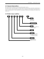
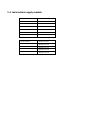
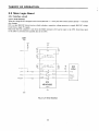
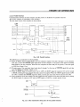
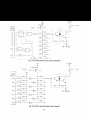
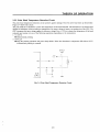
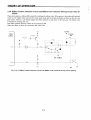
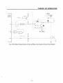
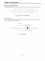
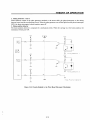
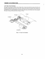
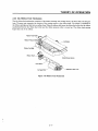
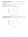
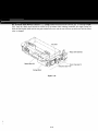
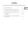
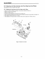
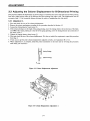
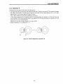
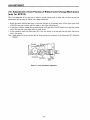
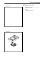
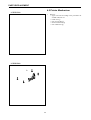
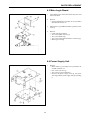
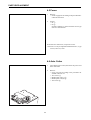
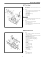
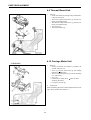
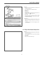
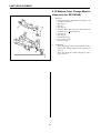
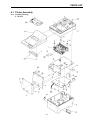
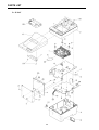
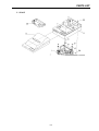
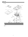
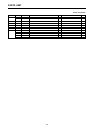
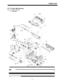
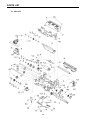
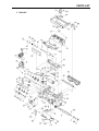
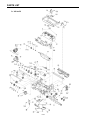
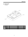
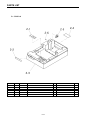
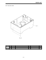
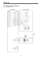
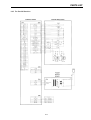
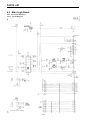
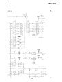
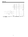
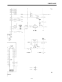
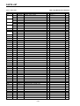
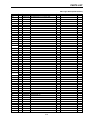
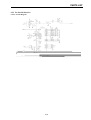
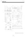
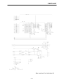
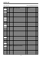
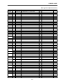
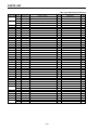
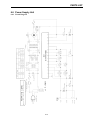
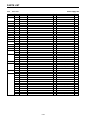
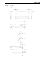
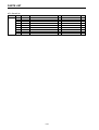
DOT MATRIX PRINTER
SP200F SERIES
TECHNICAL MANUAL
[FOURTH
EDITION]
INTRODUCTION
This manual describes the dot matrix printer SP200F series.
It is designed for use as a reference for periodic inspections and maintenance procedures to be executed
by service personnel. It is not intended for the general user. Users of this manual should have a basic
knowledge and understanding of the English language.
• This manual is divided into the following sections:
Chapter 1
Chapter 2
Chapter 3
Chapter 4
Chapter 5
Chapter 6
•
•
•
•
First edition:
General Descriptions
Theory of Operation
Adjustments
Parts Replacement
Maintenance and Lubrication
Parts List
January 1994
Second edition: August 1994
Third edition:
February 1997
Fourth edition: April 1998
NOTICE
• All rights reserved. Reproduction of any part of this manual in any form whatsoever, without
STAR’s express permission is forbidden.
• The contents of this manual are subject to change without notice.
• All efforts have been made to ensure the accuracy of the contents of this manual at the time of going
to press. However, should any errors be detected, STAR would greatly appreciate being informed
of them.
• The above notwithstanding, STAR can assume no responsibility for any errors in this manual.
© Copyright 1994 Star Micronics Co.,Ltd.
1
2
3
4
5
6
CHAPTER 1
GENERAL DESCRIPTIONS
1.1 General description ....................................................................... 1-1
1.2 Model name notation ..................................................................... 1-1
1.3 Instructions apply models ............................................................. 1-2
1
GENERAL DESCRIPTION
1.1 General description
This manual describes the SP200F series dot matrix printers listed in section 1.3.
The manual includes sections on principles of operation, adjustments, part replacement, maintenance and lubrication as
well as a list of parts. This manual has been prepared for use by a maintenance staff carrying out regular inspections or
repairs when abnormalities occur. This manual has been prepared for maintenance staff operating in the field and not for
ordinary users.
1.2 Model name notation
SP2
1
2
F
D
42
—
120
Voltage
120: AC120V
230: AC230V
240: AC240V
N. of print columns
42: 42 columns (at 16CPI)
Interface
D: Serial interface (RS-232C)
C: Parallel interface
Paper feed
F: Friction
Mechanism
2: 42 columns (at 16CPI)
6: 2 colours (Red, Black)
42 columns (at 16CPI)
Printer type
1: Standard type
4: Auto cutter type
SP200 Series printer
1-1
1.3 Instructions apply models
Serial interface
Parallel interface
SP212FD42-120
SP212FC42-120
SP212FD42-230
SP212FC42-230
SP212FD42-240
SP212FC42-240
SP216FD42-120
SP216FC42-120
SP216FD42-230
SP216FC42-230
SP216FD42-240
SP216FC42-240
Serial interface
Parallel interface
SP242FC42-120
SP242FC42-230
SP246FC42-120
SP246FC42-230
CHAPTER 3
ADJUSTMENTS
This printer is adjusted in a variety of ways to obtain the prescribed performance. This chapter explains those adjustments.
When replacing parts during maintenance inspections or after a problem occurs, double check the adjustments afterwards.
3.1 Tools and Measuring Instruments ........................................................................ 3-1
3.2 Adjusting the Gap between the Print Head and the Platen .................................. 3-2
3.2.1
Adjusting the Gap between the Print Head and the Platen ...................... 3-2
3.3 Adjusting the Column Displacement for Bi-Directional Printing ............................ 3-4
3.4.1
Adjustment A ............................................................................................ 3-4
3.4.2
Adjustment B ............................................................................................ 3-5
3.4 Adjustment of Cam Position of Ribbon Color Change Mechanism
(only for SP216/246) ............................................................................................ 3-6
3
CHAPTER 4
PARTS REPLACEMENT
This chapter explains disassembly and reassembly of the printer. Note the following precautions during
disassembly and reassembly.
1. Disconnect the printer power cord plug from the wall outlet before servicing it.
2. Assembly is the reverse of disassembly unless otherwise specified.
3. After reassembly, coat the screw heads with locking sealant.
4. Lubrication information is not provided in this chapter, Refer to Section 5.2
4.1 Upper Case Unit.......................................................... 4-1
4.2 Printer Mechanism ..................................................... 4-2
4.3 Main Logic Board ....................................................... 4-3
4.4 Power Supply Unit ...................................................... 4-3
4.5 Fuses ........................................................................... 4-4
4.6 Auto Cutter .................................................................. 4-4
4.7 Print Head.................................................................... 4-5
4.8 Drive Shaft Unit........................................................... 4-5
4.9 Thermal Board Unit .................................................... 4-6
4.10 Carriage Motor Unit .................................................. 4-6
4.11 Paper End Switch Board Unit .................................. 4-7
4.12 Ribbon Color
Change Mechanism (only for SP216/246) ............ 4-8
4
PARTS REPLACEMENT
4.1 Upper Case Unit
<SP212/216>
<SP242/246>
4-1
1.
Turn off the power switch 1, disconnect the power
cord from the wall outlet.
2.
Remove
• Four tapping screws 2.
PARTS REPLACEMENT
4.2 Printer Mechanism
<SP212/216>
1.
<SP242/246>
4-2
Remove
• Upper case unit according to the procedure described in Section 4.1
• Cable Unit 1
• Four screws SP2 2
• Printer mechanism 3
• Four rubber feet 4
PARTS REPLACEMENT
4.3 Main Logic Board
1.
Turn off the power switch, disconnect the power cord
from wall outlet.
2.
Remove
• Printer Mechanism according to the procedure
described in Section 4.2
3.
Main Chassis 1 and Board Chassis 2 from Lower
Case 3.
4.
Remove
• Cable unit and connector
• Two screws(Main chassis) 4
• Two screws(Board) 5
• Two screws and spacers(interface connector) 6
• Main logic board 7
4.4 Power Supply Unit
1.
4-3
Remove
• Main chassis 1 according to the procedure described in Section 4.3.
• One screw with wire 3
• Two screws 2 for transformer
• Remove the power supply cord 4, the power
switch 5 and the power supply unit 6 by sliding
it.
PARTS REPLACEMENT
4.5 Fuses
1.
Remove
• Printer supply unit according to the procedure described in Section4.4.
2.
Inspect
• F1 1
• F2 2
If a fuse is defective, replace with the correct type
of fuse as listed below:
Note:If the new fuse blows, inspect the circuit.
*:Fuse F2 is to only be replaced with Bell Fuse Inc., Type
5TT3A, rated 3A, 125V.
4.6 Auto Cutter
4-4
1.
Turn off the power switch, disconnect the power cord
from wall outlet.
2.
Remove
• Upper case unit according to the procedure described in Section 4.1.
• Two screws 1
• Holder plate unit (L) 2
• Holder plate unit (R) 3
• Auto cutter 4
PARTS REPLACEMENT
4.7 Print Head
1.
Turn off the power switch, disconnect the power cord
from wall outlet.
2.
Remove
• Upper case unit(not shown in the figure)according
to the procedure described in Section 4.1.
• Two screws 1
• Head cover 2
• Two tapping screws 3
• Head cable 4
• Print head 5
WARNING
The print head becomes hot after printing so wait
for it to cool before removing it.
3.
Adjust
• Gap between print head and platen
(Refer to Section 3.2.)
• Column displacement for bi-directional printing
(Refer to Section 3.3.)
4.8 Drive Shaft Unit
4-5
1.
Remove
• Upper case unit according to the procedure described in Section 4.1.
• Print head according to the procedure described
in Section 4.7.
• One screw 1 (Ribbon Base)
• Ribbon base (not shown in the figure)
• One screw 2 (Ribbon shaft guide 3 )
• Stop ring 4
• Paper feed clutch unit 5
• Stop ring 6
• Gear 7
• Stop ring 8
• Drive shaft gear L 9
• Clutch claw gear ;
• Stop ring A
• Drive shaft bearing B
• Stop ring C
• Carriage guide stay D
• Worm gear E
• Drive shaft unit F
2.
Adjust
• Column displacement
Refer to Section 3.3.
PARTS REPLACEMENT
4.9 Thermal Board Unit
1.
Remove
• Printer mechanism according to the procedure described in Section4.2.
• The eleven soldered lead wires 1 with the soldering iron.(MP212/242)
• The thirteen soldered lead wires 1 with the soldering iron.(MP216/246)
• Two screws 2
• Thermal board unit 3
4.10 Carriage Motor Unit
<SP212/242>
1.
Remove
• Printer mechanism according to procedure described in Section 4.2.
• Screw 1 and the ribbon base 2 after sliding
blackarrow
direction.
• The two soldered lead wires 3 with the soldering
iron. (black,red)
• Screw 4
• Lift the unit to white arrow direction after
wildering the frame.
• Carriage motor unit 5 .
2. Adjustment
After assembling,adjust the column displacement according to the procedure described in 3.3.
4-6
PARTS REPLACEMENT
<SP216/246>
1.
Removal
• Remove the printer mechanism according to the
procedure of item 4.2.
• Two solderd lead wires (Black and red)
• Stop ring 1
• Gear 2
• Stop ring 3
• Slide the ribbon base (W) 4 in the direction of
the black arrow
and remove it.
• Screw 5
• Secure the frame and forcibly open the carriage
motor unit in the direction of the white arrow .
• Carriage motor unit 6
2.
Adjustment
• After assembling, adjust the cam position of the
ribbon color change mechanism by referring to
item 3.4.
• After that, adjust the column slippage by referring to item 3.3.
4.11 Paper End Switch Board Unit
1.
4-7
Remove
• Printer mechanism according to the procedure described in Section 4.2.
• The two soldered lead wires 1 with the soldering
iron. (White)
• Screw 2
• Paper end switch board unit 3
PARTS REPLACEMENT
4.12 Ribbon Color Change Mechanism (only for SP216/246)
4-8
1.
Removal
• Remove the printer mechanism according to the
procedure of item 4.2.
• Stop ring 1
• Gear 2
• Stop ring 3
• Slide the ribbon base (W) 4 in the direction of
the black arrow
and remove it.
• Cam gear 5
• Stop ring 6
• RS cluttch unit 7
• Gear 12×24×0.4 8
• Gear 28×0.4 9
2.
Adjustment
• After assembling, adjust the cam position of the
ribbon color change mechanism by referring to
item 3.4.
• After that, adjust the column slippage by referring to item 3.3.
CHAPTER 6
PARTS LIST
HOW TO USE PARTS LIST
1. DRWG. NO.
This column shows the drawing number of the illustration.
2. REVISED EDITION MARK
This column shows a revision number.
Parts that have been added in the revised edition are indicated with “#”.
Parts that have been abolished in the revised edition are indicated with “*”.
#1: First edition → Second edition
#2: Second edition → Third edition
*1: First edition → Second edition
*2: Second edition → Third edition
3. PARTS NO.
Parts numbers must be indicated when ordering replacement parts.
4. PARTS NAME
Parts name must be indicated when ordering replacement parts.
5. Q’TY
This column shows the number of the part used indicated in the figure.
6. REMARKS
When there are differences in the specifications of the fuse, destinations, etc., the differences are described in
words or indicated by two letters.
US ... U.S.A. EC ... EC
UK ... United Kingdom AS ... Australia
The seal number of ROM is described in this column. The “**” mark of seal number is variable depending on
the software version.
7. RANK
Parts marked “S” are service parts.
Service parts are recommended for maintenance.
6.1
Printer Assembly .......................... 6-1
6.1.1 Assembly Drawing ............... 6-1
6.1.2 Parts List .......................... 6-5
6.2
Printer Mechanism ........................ 6-7
6.2.1 Assembly Drawing ............... 6-7
6.2.2 Parts List ......................... 6-11
6.3
Sub-assembly ............................ 6-13
6.3.1 Upper Case Unit ................. 6-13
6.3.2 Lower Case Unit ................ 6-15
6.4
Wiring Schematic of Printer ............ 6-16
6.4.1 For Serial Interface ............. 6-16
6.4.2 For Parallel Interface .......... 6-17
6.5
Main Logic Board ........................ 6-18
6.5.1 For Serial Interface ............. 6-18
6.5.1.1 Circuit Diagram ............. 6-18
6.5.1.2 Parts List ..................... 6-22
6.5.2 For Parallel Interface .......... 6-25
6.5.2.1 Circuit Diagram ............. 6-25
6.5.2.2 Parts List ..................... 6-28
6.6
Power Supply Unit ....................... 6-31
6.6.1 Circuit Diagram ................. 6-31
6.6.2 Parts List ......................... 6-32
6.7
Terminal Board ........................... 6-33
6.7.1 Circuit Diagram ................. 6-33
6.7.2 Parts List ......................... 6-34
6
PARTS LIST
6.1 Printer Assembly
6.1.1 Assembly Drawing
A. SP212F
6-1
PARTS LIST
B. SP216F
6-2
PARTS LIST
C. SP242F
6-3
PARTS LIST
D. SP246F
6-4
PARTS LIST
1
#1
38000210
38000610
MP212FP-24
MP216FP-24
1
1
6-5
SP212
SP216
S
S
PARTS LIST
Printer Assembly
DRWG.NO. REV. PARTS NO.
25
*3
30980210
#3
30980211
26
04991204
27
#3
33400010
28
#3
33910150
29
#3
00920803
30
#3
01903055
#2
09990723
#2
04991204
*2
37300610
#2
37300611
PARTS NAME
INK RIBBON CARTRIDGE RC200BR
INK RIBBON CARTRIDGE RC200BR
FASTENER T18S
HOLDER LEVER
SP24
HOLDER
SP24
SCREW TAT 2-8 PT
SCREW TR 3-8 WS/WF
FERRITE CORE TFC-23-11-14
FASTENER T18S
TERMINAL COVER UNIT
SP2
TERMINAL COVER UNIT
SP2
6-6
Q’TY
1
1
1
1
1
1
1
1
1
1
1
REMARKS
BLACK/RED
BLACK/RED
SP242/246
SP242/246
SP242/246
SP242/246
FOR EC,UK(230V)
FOR EC,UK(230V)
OPTION
OPTION :SP212/216
RANK
S
S
S
S
S
PARTS LIST
6.2 Printer Mechanism
6.2.1 Assembly Drawing
A. MP212FP
6-7
PARTS LIST
B. MP216FP
6-8
PARTS LIST
C. MP242FP
6-9
PARTS LIST
D. MP246FP
6-10
PARTS LIST
6.2.2 Parts List
DRWG.NO. REV. PARTS NO.
1
38100110
2
37000010
#1
37000020
3
*2
34920010
#2
37001010
4
80203041
6
82500040
7
33140010
8
*2
37001310
#2
37001111
8-1
04020016
8-2
*2
82500040
#2
8-3
*2
81301760
#2
81301761
10
31360111
11
31360121
14
*2
33910011
#2
37003010
14-1
04020016
14-2
02205002
14-3
30520120
14-4
02305025
14-5
*1
82500430
#1
82500430
15
31375010
16
33902010
20
32980010
*2
32980020
#2
32980021
21
32910010
22
37002020
23
37002010
24
32981010
25
33980010
26
33140110
27
*2
37008310
#2
37008010
31
37007610
32
*3
37007010
#3
37007011
*3
37007020
#3
37007021
33
*1
33101120
*1
33101120
#1
33101121
34
33100020
39
33101220
40
33102110
41
33102010
43
*2
30520110
#2
30520100
44
33110010
Printer Mechanism
PARTS NAME
DP200-24
FRAME UNIT
FRAME UNIT
DRIVE SHAFT
DRIVE SHAFT UNIT
DRIVE SHAFT BEARING
WAVE WASHER 1
WORM GEAR
CARRIAGE ASSY
CARRIAGE UNIT
STOP RING SE4.0
WAVE WASHER 1
HALF-NUT
HALF-NUT
CARRIAGE STAY
CARRIAGE GUIDE STAY
PAPER GUIDE
PAPER GUIDE UNIT
STOP RING SE4.0
PLAIN WASHER WF5X10X0.8
SPRING C070-060-0140
POLY-SLIDER WP5X0.25
WASHER 5.2X0.15
WASHER 5.2X0.15
PLATEN
PLATEN BASE
RIBBON BASE S
RIBBON BASE W
RIBBON BASE W
HEAD COVER
PE SWITCH UNIT
MOTOR 24V UNIT
RIBBON SHAFT GUIDE
RIBBON SHAFT
WORM WHEEL
COIL 24V ASSY
SOLENOID 24V UNIT
TIMING DETECTOR BD UNIT
TERMINAL BOARD UNIT
TERMINAL BOARD UNIT
TERMINAL BOARD UNIT
TERMINAL BOARD UNIT
CLUTCH CLAW GEAR
CLUTCH CLAW GEAR
CLUTCH CLAW GEAR
DRIVE SHAFT GEAR L
INTERMITTENT GEAR R
GEAR 28X0.5
PAPER FEED GEAR
SPRING C095-060-0090
SPRING C094-060-0073
PAPER FEED RATCHET
6-11
MP2
MP216
MP2
MP2
MP300
DT
MP2
MP2
MP2
DT
MP300
MP300
MP2
MP2
MP2
MP2
832
832
MP2
MP2
MP2
MP2
MP2
MP2
MP2
MP2
MP2
MP2
MP2
MP2
MP2
MP2
MP2
MP2
MP216
MP216
MP2
MP2
MP2
MP2
MP2
MP2
MP2
MP2
Q’TY
1
1
1
1
1
1
1
1
1
1
1
1
1
1
1
1
1
1
1
1
1
1
3
1
1
1
1
1
1
1
1
1
1
1
1
1
1
1
1
1
1
1
1
1
1
1
1
1
1
1
1
1
REMARKS
RANK
S
MP212/242
MP216/246
VER.1
VER.2
S
VER.1
NOT USED
VER.1
VER.2
:VER.2
S
S
MP212/242
MP216/246
MP216/246
S
S
S
S
S
MP212/242
MP212/242
MP216/246
MP216/246
PARTS LIST
Printer Mechanism
DRWG.NO. REV. PARTS NO.
46
04020015
47
04020016
48
04020010
#1
04020010
51
*2
01902620
#2
01902631
52
00626404
53
00926503
#3
00926503
54
00926803
55
*2
01902617
#2
01902618
56
01902617
57
33100110
59
01902622
60
02205001
62
*2
37008320
#2
37008020
63
#1
33102120
67
#1
33100120
68
#1
33101310
70
#1
37006020
71
#1
37004010
72
#3
37002620
73
#3
37000560
74
#3
37000550
75
#3
30290110
76
#3
04991204
PARTS NAME
STOP RING SE3.0
STOP RING SE4.0
STOP RING SE2.0
STOP RING SE2.0
SCREW TAT 2.6-14 PT
SCREW TAT 2.6-14 PT-WF
SCREW TR 2.6-4
SCREW TAT 2.6-5 CT
SCREW TAT 2.6-5 CT
SCREW TAT 2.6-8 PT
SCREW TAT 2.6-5 CT-FL
SCREW TAT 2.6-4
SCREW TAT 2.6-5 CT-FL
GEAR 12X45X0.4
SCREW TAT 2.6-5 WF
PLAIN WASHER WF5X12X0.8
COIL 24V ASSY
SOLENOID 24V UNIT
GEAR 28X0.4
GEAR 12X24X0.4
CAM GEAR
PAPER FEED CLUTCH UNIT
RS CLUTCH UNIT
CUTTER ACS230 UNIT
HOLDER PLATE UNIT L
HOLDER PLATE UNIT R
STOPPER RUBBER
FASTENER T18S
6-12
MP2
MP216
MP216
MP216
MP216
MP216
MP2
MP216
MP24
MP24
MP24
MP2
Q’TY
1
3
4
5
2
2
2
3
5
3
3
3
2
1
1
1
1
1
1
1
1
1
1
1
1
1
1
1
REMARKS
RANK
S
S
MP212/242
MP216/246
MP212/216
MP242/246
S
S
S
S
S
S
S
MP216/246
MP216/246
MP216/246
MP216/246
MP216/246
MP216/246
MP242/246
MP242/246
MP242/246
MP242/246
MP242/246
S
S
PARTS LIST
6.3 Sub-assembly
6.3.1 Upper Case Unit
A. SP212/216
DRWG.NO. REV. PARTS NO.
2-1
30060010
2-2
30070010
2-3
*2
33021020
#2
33021022
2-4
30060110
PARTS NAME
OPERATION SHEET
BRAND SEAL
UPPER CASE
UPPER CASE
PAPER SET SEAL
6-13
SP2
SP2
SP2
SP2
SP2
Q’TY
1
1
1
1
1
REMARKS
RANK
PARTS LIST
B. SP242/246
DRWG.NO. REV. PARTS NO.
2-1
30060010
2-2
30070010
2-3
33021080
2-4
30060110
2-5
33910150
2-6
00920803
PARTS NAME
OPERATION SHEET
BRAND SEAL
UPPER CASE
PAPER SET SEAL
HOLDER
SCREW TAT 2-8 PT
6-14
SP2
SP2
SP24
SP2
SP24
Q’TY
1
1
1
1
1
1
REMARKS
RANK
PARTS LIST
6.3.2 Lower Case Unit
DRWG.NO. REV. PARTS NO.
PARTS NAME
3-1
*2
33021010 LOWER CASE
#2
33021011 LOWER CASE
3-2
80991610 RUBBER FOOT
6-15
SP2
SP2
NB24-10
Q’TY
1
1
2
REMARKS
RANK
PARTS LIST
6.4 Wiring Schematic of Printer
6.4.1 For Serial Interface
6-16
PARTS LIST
6.4.2 For Parallel Interface
6-17
PARTS LIST
6.5 Main Logic Board
6.5.1 For Serial Interface
6.5.1.1 Circuit Diagram
6-18
PARTS LIST
6-19
PARTS LIST
6-20
PARTS LIST
6-21
PARTS LIST
6.5.1.2 Parts List
Main Logic Board (Serial Interface)
DRWG.NO. REV. PARTS NO.
IC1
IC2
IC3
IC4
IC5
IC6
IC7
IC8
IC9
R1
R2
R3-4
R5
R6-7
R8
R9
R10
R11
R12
R13
R14
R15
R16
R17
R18-20
R21
R22-23
R24
R25-26
R27
R28-29
R30
R31-39
R40
R41-42
R43
R44
R45-47
R48
R49
R50
R51
R52
R53
R54
R55-56
R57-58
R59-60
*3
#3
*3
#3
*3
#3
*3
#3
PARTS NAME
Q’TY
08222026
08210142
08210126
08200155
08200157
08210141
08211037
08210143
08211038
08250018
EPROM 27256-150NS
TTL IC 74LS05FP*TL
TTL IC 74LS05FP*EL
IC-I/F HD151232FP*TL
IC-I/F ADM232LJR*SOL16
TTL IC 74LS04FP*TL
TTL IC 74LS04FP*EL
TTL IC 74LS32FP*TL
TTL IC 74LS32FP*EL
CPU M37732S4AFP
1
1
1
1
1
1
1
1
1
1
08210142
08210126
08200109
06054725
06054714
TTL IC 74LS05FP*TL
TTL IC 74LS05FP*EL
IC-RESET M51953BL
RD RESISTOR 4.7 K-OHM 1/6W
RD RESISTOR 470 OHM 1/6W
1
1
1
1
1
06054714
06052211
06058224
06054725
06058224
06054725
06058224
06054725
06051034
06058224
06054725
06058224
06051034
06053314
06054714
06053314
06051535
06054714
06051044
06051034
06053314
06053314
06054725
06052234
06054714
06051034
06054714
06052224
06051034
06251034
06054725
06051525
06054725
06054714
06054725
06051034
RD
RD
RD
RD
RD
RD
RD
RD
RD
RD
RD
RD
RD
RD
RD
RD
RD
RD
RD
RD
RD
RD
RD
RD
RD
RD
RD
RD
RD
RN
RD
RD
RD
RD
RD
RD
1
2
1
1
1
1
1
1
1
1
1
1
3
1
2
1
2
1
2
1
9
1
2
1
1
3
1
1
1
1
1
1
1
2
2
2
REMARKS
SP2S.F.**
NOT MOUNTED
*3
#3
NOT USED
#1
RESISTOR
RESISTOR
RESISTOR
RESISTOR
RESISTOR
RESISTOR
RESISTOR
RESISTOR
RESISTOR
RESISTOR
RESISTOR
RESISTOR
RESISTOR
RESISTOR
RESISTOR
RESISTOR
RESISTOR
RESISTOR
RESISTOR
RESISTOR
RESISTOR
RESISTOR
RESISTOR
RESISTOR
RESISTOR
RESISTOR
RESISTOR
RESISTOR
RESISTOR
RESISTOR
RESISTOR
RESISTOR
RESISTOR
RESISTOR
RESISTOR
RESISTOR
470 OHM 1/6W
220 OHM 1/6W
8.2 K-OHM 1/6W
4.7 K-OHM 1/6W
8.2 K-OHM 1/6W
4.7 K-OHM 1/6W
8.2 K-OHM 1/6W
4.7 K-OHM 1/6W
10 K-OHM 1/6W
8.2 K-OHM 1/6W
4.7 K-OHM 1/6W
8.2 K-OHM 1/6W
10 K-OHM 1/6W
330 OHM 1/6W
470 OHM 1/6W
330 OHM 1/6W
15 K-OHM 1/6W
470 OHM 1/6W
100 K-OHM 1/6W
10 K-OHM 1/6W
330 OHM 1/6W
330 OHM 1/6W
4.7 K-OHM 1/6W
22 K-OHM 1/6W
470 OHM 1/6W
10 K-OHM 1/6W
470 OHM 1/6W
2.2 K-OHM 1/6W
10 K-OHM 1/6W
10 K-OHM 1/6W
4.7 K-OHM 1/6W
1.5 K-OHM 1/6W
4.7 K-OHM 1/6W
470 OHM 1/6W
4.7 K-OHM 1/6W
10 K-OHM 1/6W
6-22
SP216
RANK
PARTS LIST
Main Logic Board (Serial Interface)
DRWG.NO. REV. PARTS NO.
R61
R62
R63
R64-65
R66
R67-69
C1-3
C4
C5-8
C9
C10-12
C13
C14
C15
C16-17
C18
C19
C20
C21-22
C23
C24
C25
C26
C27-28
BC1
BC2-3
BC4
BC5-6
BC7
BC8-10
TA1-2
TR1
TR2
TR3
TR4-10
TR11
TR12
TR13
REG1
D1-2
D3
D4
LED1-2
RA1
RA2
RA3
RA4-5
RA6
RA7
RA8
RA9
06054725
06051051
06052211
06054725
06051535
06051034
PARTS NAME
RD
RD
RD
RD
RD
RD
RESISTOR
RESISTOR
RESISTOR
RESISTOR
RESISTOR
RESISTOR
4.7 K-OHM 1/6W
1 M-OHM 1/6W
220 OHM 1/6W
4.7 K-OHM 1/6W
15 K-OHM 1/6W
10 K-OHM 1/6W
Q’TY
REMARKS
1
1
1
2
1
3
NOT USED
NOT MOUNTED
05052255
CHEM. CAPA. 2.2UF 50V
4
05152212
05151042
05151033
05152234
05152225
05152234
05154714
05152234
05151015
05152212
CERA.
CERA.
CERA.
CERA.
CERA.
CERA.
CERA.
CERA.
CERA.
CERA.
220PF 50V
0.1UF 50V
0.01UF 50V
0.022UF 50V
2200PF 50V
0.022UF 50V
470PF 50V
0.022UF 50V
100PF 50V
220PF 50V
3
1
1
1
2
1
1
1
1
2
05152234
CERA. CAPA. 0.022UF 50V
1
05152234
05131044
05532234
05152234
05131044
05152234
CERA. CAPA. 0.022UF 50V
CERA. CAPA. 0.1UF 25V
CAPACITOR 0.022UF 25V
CERA. CAPA. 0.022UF 50V
CERA. CAPA. 0.1UF 25V
CERA. CAPA. 0.022UF 50V
1
2
1
2
1
2
05152234
07650048
07650056
07320101
07227853
07009502
CERA. CAPA.
TRANSISTOR
TRANSISTOR
TRANSISTOR
TRANSISTOR
TRANSISTOR
3
2
2
1
1
1
07320101
TRANSISTOR 2SD2010
1
07320101
08202011
08000040
08000040
08000040
08300136
06584724
06581032
06581036
06581037
06581032
06581023
06581026
06581030
TRANSISTOR 2SD2010
IC-REG UPC7824
DIODE DSM1D1
DIODE DSM1D1
DIODE DSM1D1
LED SLZ-390B
RESIS. ARRAY 4.7K-OHM 1/8W 5EL
RESIS. ARRAY 10 K-OHM 1/8W 8EL
RESIS. ARRAY 10 K-OHM 1/8W 5EL
RESIS. ARRAY 10 K-OHM 1/8W 7EL
RESIS. ARRAY 10 K-OHM 1/8W 8EL
RESIS. ARRAY 1 K-OHM 1/8W 4EL
RESIS. ARRAY 1 K-OHM 1/8W 7EL
RESIS. ARRAY 10 K-OHM 1/8W 3EL
1
1
2
1
1
2
1
1
1
2
1
1
1
1
NOT MOUNTED
*1
#1
CAPA.
CAPA.
CAPA.
CAPA.
CAPA.
CAPA.
CAPA.
CAPA.
CAPA.
CAPA.
NOT USED
NOT USED
NOT MOUNTED
*2
#2
#1
#1
0.022UF 50V
ARRAY STA471A=S
ARRAY UPA1428AH
2SD2010
2SC1740SE
2SA950
6-23
NOT USED
SP216
NOT USED
SP216
RANK
PARTS LIST
Main Logic Board (Serial Interface)
DRWG.NO. REV. PARTS NO.
CA1
05652212
CA2
05651012
CA3
05651018
CN1
09100566
CN2
09100567
CN3
09100495
CN4
09100317
CN5
DSW1
09090054
SW1-2
09010055
X1
09250047
L1
09990705
PARTS NAME
CAPA. ARRAY 220PF 50V 8EL
CAPA. ARRAY 100PF 50V 8EL
CAPA. ARRAY 100PF 50V 7EL
CONNECTOR 17JE-13250-37
CONNECTOR 95003-2661
CONNECTOR HLEM23S-1
CONNECTOR 5483-04A
Q’TY
1
1
1
1
1
1
1
REMARKS
NOT USED
DIP SWITCH SD-10ZL
PUSH SWITCH SKHHLN
CERA. OSCILLATOR CST8.0MTW
BEADS INDUCTOR B01-RT
6-24
1
2
1
1
RANK
PARTS LIST
6.5.2 For Parallel Interface
6.5.2.1 Circuit Diagram
6-25
PARTS LIST
6-26
PARTS LIST
6-27
PARTS LIST
6.5.2.2 Parts List
Main Logic Board (Parallel Interface)
DRWG.NO. REV. PARTS NO.
IC1
IC2
*3
#3
IC3
IC4
IC5
IC6
IC7
IC8
IC9
R1
PARTS NAME
Q’TY
08222026
08210142
08210126
08240072
EPROM 27256-150NS
TTL IC 74LS05FP*TL
TTL IC 74LS05FP*EL
GATE ARRAY HG62E11R77FBSPII
1
1
1
1
08210127
TTL IC 74LS06FP*EL
1
08250018
CPU
1
M37732S4AFP
08200109
IC-RESET M51953BL
1
#3
06051535
RD RESISTOR 15 K-OHM 1/6W
1
#3
06053324
06055614
RD RESISTOR 3.3 K-OHM 1/6W
RD RESISTOR 560 OHM 1/6W
1
1
06051025
06051825
RD RESISTOR 1 K-OHM 1/6W
RD RESISTOR 1.8 K-OHM 1/6W
1
1
#3
06051535
RD RESISTOR 15 K-OHM 1/6W
1
#3
#3
#3
06053324
06054734
06054725
06051535
RD
RD
RD
RD
1
1
1
1
06055614
RD RESISTOR 560 OHM 1/6W
1
06053314
06051535
RD RESISTOR 330 OHM 1/6W
RD RESISTOR 15 K-OHM 1/6W
1
2
06051044
06051034
RD RESISTOR 100 K-OHM 1/6W
RD RESISTOR 10 K-OHM 1/6W
2
1
06053314
06053314
06054725
06052234
06055114
06051034
RD
RD
RD
RD
RD
RD
9
1
2
1
1
1
06055114
06051034
RD RESISTOR 510 OHM 1/6W
RD RESISTOR 10 K-OHM 1/6W
1
1
06055114
06052224
06051034
06251034
06054725
06051525
06054725
06054714
RD
RD
RD
RN
RD
RD
RD
RD
1
1
1
1
1
1
1
2
R3
R4
R5
R6
R7
R46
R47
R48
R49
R50
R51
R52
R53
R54
R55-56
NOT MOUNTED :SP212/6
:SP242/246
NOT MOUNTED :SP212/6
:SP242/246
NOT MOUNTED
R8
R31-39
R40
R41-42
R43
R44
R45
NOT MOUNTED :SP212/6
:SP242/246
NOT USED
NOT MOUNTED
NOT USED
R2
R9
R10
R11
R12-21
R22
R23
R24
R25-26
R27
R28-29
R30
REMARKS
SP2P.F.**
RESISTOR
RESISTOR
RESISTOR
RESISTOR
3.3 K-OHM 1/6W
47 K-OHM 1/6W
4.7 K-OHM 1/6W
15 K-OHM 1/6W
NOT MOUNTED :SP212/6
:SP242/246
NOT MOUNTED :SP212/6
:SP242/246
NOT USED
NOT MOUNTED
NOT USED
*3
#3
#3
*3
#3
*3
#3
NOT USED
RESISTOR
RESISTOR
RESISTOR
RESISTOR
RESISTOR
RESISTOR
330 OHM 1/6W
330 OHM 1/6W
4.7 K-OHM 1/6W
22 K-OHM 1/6W
510 OHM 1/6W
10 K-OHM 1/6W
:SP216/246
NOT USED
NOT USED
RESISTOR
RESISTOR
RESISTOR
RESISTOR
RESISTOR
RESISTOR
RESISTOR
RESISTOR
510 OHM 1/6W
2.2 K-OHM 1/6W
10 K-OHM 1/6W
10 K-OHM 1/6W
4.7 K-OHM 1/6W
1.5 K-OHM 1/6W
4.7 K-OHM 1/6W
470 OHM 1/6W
6-28
RANK
PARTS LIST
Main Logic Board (Parallel Interface)
DRWG.NO. REV. PARTS NO.
R57-58
R59-60
R61
R62
R63
R64-65
R66
R67-69
R70-77
R78
R79
R80-83
R84
R85-87
R88
R89
R90
R91-92
C1
C2
C3
PARTS NAME
RESISTOR
RESISTOR
RESISTOR
RESISTOR
RESISTOR
RESISTOR
RESISTOR
Q’TY
06054725
06051034
06054725
06051051
06052211
06054725
06051535
RD
RD
RD
RD
RD
RD
RD
4.7 K-OHM 1/6W
10 K-OHM 1/6W
4.7 K-OHM 1/6W
1 M-OHM 1/6W
220 OHM 1/6W
4.7 K-OHM 1/6W
15 K-OHM 1/6W
2
2
1
1
1
2
1
06054725
06051025
06051014
RD RESISTOR 4.7 K-OHM 1/6W
RD RESISTOR 1 K-OHM 1/6W
RD RESISTOR 100 OHM 1/6W
8
1
1
06051034
RD RESISTOR 10 K-OHM 1/6W
1
#3
06054725
RD RESISTOR 4.7 K-OHM 1/6W
1
#3
06054734
RD RESISTOR 47 K-OHM 1/6W
1
NOT USED
NOT USED
NOT USED
NOT USED
NOT MOUNTED
NOT MOUNTED
05154714
CERA. CAPA. 470PF 50V
1
#3
05151042
CERA. CAPA. 0.1UF 50V
1
*1
#1
05151042
05151033
05152234
05152225
05152234
05154714
05152234
CERA.
CERA.
CERA.
CERA.
CERA.
CERA.
CERA.
1
1
1
2
1
1
1
#3
05151042
CERA. CAPA. 0.1UF 50V
1
#3
05152234
CERA. CAPA. 0.022UF 50V
1
05152234
CERA. CAPA. 0.022UF 50V
1
05152234
05152234
05131044
CERA. CAPA. 0.022UF 50V
CERA. CAPA. 0.022UF 50V
CERA. CAPA. 0.1UF 25V
1
1
2
C4-8
C9-10
C11-12
C13
C14
C15
C16-17
C18
C19
NOT MOUNTED :SP212/6
:SP216/246
NOT USED
NOT MOUNTED
NOT USED
CAPA.
CAPA.
CAPA.
CAPA.
CAPA.
CAPA.
CAPA.
0.1UF 50V
0.01UF 50V
0.022UF 50V
2200PF 50V
0.022UF 50V
470PF 50V
0.022UF 50V
C20
C21
C22-23
C24
C25
#3
C26
C27-28
C29
C30-31
#3
C32-33
BC1
BC2-5
BC6
BC7
BC8
#3
BC9
REMARKS
05152234
05152234
05532234
05152234
05152234
05152234
CERA. CAPA. 0.022UF 50V
CERA. CAPA. 0.022UF 50V
CAPACITOR 0.022UF 25V
CERA. CAPA. 0.022UF 50V
CERA. CAPA. 0.022UF 50V
CERA. CAPA. 0.022UF 50V
6-29
2
2
1
4
1
1
NOT MOUNTED :SP212/6
:SP242/246
NOT MOUNTED :SP212/6
:SP242/246
NOT MOUNTED
NOT MOUNTED :SP212/6
:SP242/246
NOT USED
NOT MOUNTED :SP212/6
:SP242/246
NOT USED
NOT MOUNTED
NOT MOUNTED :SP212/6
:SP242/246
RANK
PARTS LIST
Main Logic Board (Parallel Interface)
DRWG.NO. REV. PARTS NO.
TA1-2
*2
07650048
#2
07650056
TA3
#3
07650037
TR1
07320111
TR2
07227853
TR3
07009502
TR4-10
TR11
#1
07320101
TR12
TR13
07320101
REG1
08202011
D1-2
08000040
D3
#1
08000040
D4
08000040
LED1-2
08300136
RA1
06584723
RA2
RA3
06581036
RA4
06584723
RA5
RA6
RA7
06581023
RA8
06581026
RA9
06581030
RA10
06581824
R11
06581032
CA1
05651012
CA2-3
05652212
CA4
05651012
CN1
09100582
CN2
09100567
CN3
09100495
CN4
09100317
CN5
CN6
#3
09100038
DSW1
09090034
SW1-2
09010055
X1
09250047
L1-4
09990705
JA3
#3
06750004
F1
#3
09991023
PARTS NAME
TRANSISTOR ARRAY STA471A=S
TRANSISTOR ARRAY UPA1428AH
TRANSISTOR
TRANSISTOR
TRANSISTOR
TRANSISTOR
ARRAY TH3C10
2SD2011
2SC1740SE
2SA950
Q’TY
2
2
1
1
1
1
REMARKS
NOT MOUNTED :SP212/6
:SP242/246
TRANSISTOR 2SD2010
1
NOT USED
SP216/246
NOT USED
TRANSISTOR 2SD2010
IC-REG UPC7824
DIODE DSM1D1
DIODE DSM1D1
DIODE DSM1D1
LED SLZ-390B
RESIS. ARRAY 4.7K-OHM 1/8W 8EL
1
1
2
1
1
2
1
SP216/246
RESIS. ARRAY 10 K-OHM 1/8W 5EL
RESIS. ARRAY 4.7K-OHM 1/8W 8EL
1
1
NOT MOUNTED
NOT MOUNTED
NOT USED
RESIS. ARRAY 1 K-OHM 1/8W 4EL
RESIS. ARRAY 1 K-OHM 1/8W 7EL
RESIS. ARRAY 10 K-OHM 1/8W 3EL
RESIS. ARRAY 1.8K-OHM 1/8W 6EL
RESIS. ARRAY 10 K-OHM 1/8W 8EL
CAPA. ARRAY 100PF 50V 8EL
CAPA. ARRAY 220PF 50V 8EL
CAPA. ARRAY 100PF 50V 8EL
CONNECTOR 57GE-40360-751
CONNECTOR 95003-2661
CONNECTOR HLEM23S-1
CONNECTOR 5483-04A
1
1
1
1
1
1
2
1
1
1
1
1
CONNECTOR 5045-05A
DIP SWITCH KSS08-1
PUSH SWITCH SKHHLN
CERA. OSCILLATOR CST8.0MTW
BEADS INDUCTOR B01-RT
CHIP RESISTOR 0 OHM 1/10W
1
1
2
1
4
1
FUSE RXE030*
1
6-30
NOT USED
NOT MOUNTED :SP212/6
:SP242/246
NOT MOUNTED :SP212/6
:SP242/246
RANK
PARTS LIST
6.6 Power Supply Unit
6.6.1 Circuit Diagram
6-31
PARTS LIST
6.6.2
Parts List
DRWG.NO. REV. PARTS NO.
IC1
08202025
DB1
*2
08990220
#2
08990227
R1
06214721
R2
06230031
R3
06230021
R4
06201022
C1
05291045
C2-3
05192224
C4
05054782
C5
05051058
C6-7
05152223
C8
05043385
C9
05044771
SW1
*3
09030026
#3
09030036
L1
09251106
L2
09251037
L3
09251036
F1
09990058
09990021
F2
*2
09990054
#2
09991011
09990050
#1
09990051
CN1
80703850
TRNS1
30780010
30780030
30780040
#2
30780230
FB1
*2
09990703
#2
09990706
09110090
09110129
*3
09110067
#3
09110172
09110068
04991204
04991204
82911071
01903087
09990023
09990708
09992307
Power Supply Unit
PARTS NAME
IC-REG 7573B
DIODE STACK D3SB10
DIODE STACK D3SB20
RN RESISTOR 4.7 K-OHM 1W
RN RESISTOR 0.33 OHM 3W
RN RESISTOR 0.22 OHM 3W
RN RESISTOR 1 K-OHM 2W
FILM CAPA. 0.1UF 275V
CERA. CAPA. 2200PF 400V
CHEM. CAPA. 4700UF 50V
CHEM. CAPA. 1UF 50V
CERA. CAPA. 2200PF 50V
CHEM. CAPA. 3300UF 35V
CHEM. CAPA. 470UF 35V
SEESAW SWITCH T-883S3BBR1-W
SEESAW SWITCH SF-W1P1A03BB2
LINE FILTER SU10V-05050
CHOKE COIL NM-1-200
CHOKE COIL NM-16-300
FUSE 5TT1A 250V
FUSE EAWK630MA 250V
FUSE 5TT3A 125V
FUSE 5TT3A 250V
FUSE EAK3.15A 250V
FUSE EAK5A 250V
CABLE UNIT 4X120TT
SP300II
TRANSFORMER 120V SP200 US
TRANSFORMER 230V SP200 EC
TRANSFORMER 240V SP200 UK
TRANSFORMER 230V SP200W EC
BEADS INDUCTOR B-01A
BEADS INDUCTOR B-01AT
CORD SET US-PN
SP300
CORD SET EC-PN
SP300II
CORD SET UK-PN
LC
CORD SET UK-PN
SP300
CORD SET AS-PN
LC
FASTENER T18S
FASTENER T18S
RADIATION PLATE
SP312
SCREW TAT 3-14
FUSE HOLDER UF-0033
FERRITE CORE ESD-R-16C
HEAT-SHRINK TUBE F2-18X30
6-32
Q’TY
1
1
1
1
1
1
1
1
2
1
1
2
1
1
1
1
1
1
1
1
1
1
1
1
1
1
1
1
1
1
1
1
1
1
1
1
1
1
2
1
1
1
1
1
REMARKS
FOR
FOR
FOR
FOR
FOR
FOR
US
EC,UK,AS
US,UK(240V)
US,UK(240V),AS
EC
UK(230V)
FOR
FOR
FOR
FOR
US
EC,UK(230V)
UK(240V)
AS
FOR
FOR
FOR
FOR
FOR
FOR
FOR
US
EC
UK
UK
AS
US,UK(240V),AS
EC,UK(230V)
FOR EC,UK(230V)
FOR EC,UK(230V)
RANK
S
S
S
S
S
S
PARTS LIST
6.7 Terminal Board
6.7.1 Circuit Diagram
6-33
PARTS LIST
6.7.2 Parts List
DRWG.NO. REV. PARTS NO.
*1
06041518
#1
06041515
06055634
07227853
09100568
09100569
*3
09040020
#3
09040026
#1
09040024
PARTS NAME
RD RESISTOR 150 OHM 1/4W
RD RESISTOR 150 OHM 1/4W
RD RESISTOR 56 K-OHM 1/6W
TRANSISTOR 2SC1740SE
CONNECTOR HLEM23R
CONNECTOR HLEM12R
MICRO SWITCH MPU10200MLA1
MICRO SWITCH MPU10200MLA2
MICRO SWITCH MPU10101MLA0
6-34
Q’TY
REMARKS
2
2
2
2
1
1
1
1
1
SP216/246
RANK
ELECTRONIC PRODUCTS DIVISION
STAR MICRONICS CO., LTD.
536 Nanatsushinya,
Shimizu, Shizuoka, 424-0066 Japan
Tel : 0543-47-0112
Fax : 0543-48-5271
OVERSEAS SUBSIDIARY COMPANIES
STAR MICRONICS AMERICA, INC.
70-D Ethel Road West,
Piscataway, NJ 08854 U.S.A
Tel : 732-572-9512
Fax : 732-572-5095
STAR MICRONICS U.K. LTD.
Star House, Peregrine Business
Park, Gomm Road, High Wycombe,
Bucks, HP13 7DL, U.K.
Tel : 01494-471111
Fax : 01494-473333
Please access the following URL
http://www.star-micronics.co.jp/service/t_mans_e.htm
for the lastest revision of the manual.
Distributed by
1998.05.01
Printed in Japan, 30822718


![KCA-BT300 - [::] Kenwood ASC](http://vs1.manualzilla.com/store/data/006728037_1-9b378982cb2be3137434f78b86e789ba-150x150.png)