1
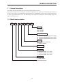
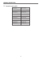
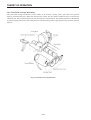
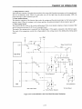
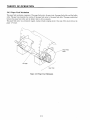
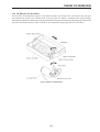
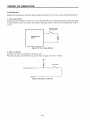
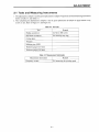
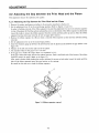
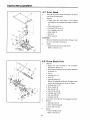
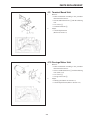
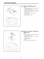
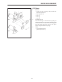
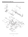
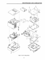
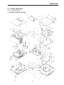
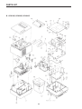
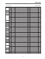
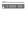
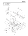
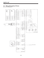
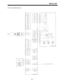
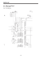
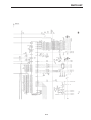
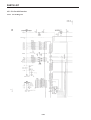
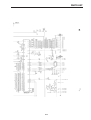
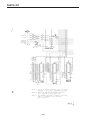
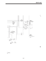
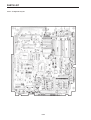
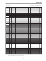
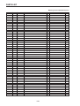
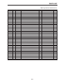
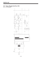
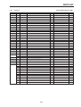
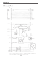
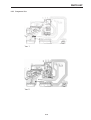
DOT MATRIX PRINTER
SP320S SERIES
TECHNICAL MANUAL
[SECOND EDITION]
CONTENTS
Chapter 1
Chapter 2
Chapter 3
Chapter 4
Chapter 5
Chapter 6
General Specifications
Theory of Operation
Adjustments
Parts Replacement
Maintenance and Lubrication
Parts List
• First edition: March 1993
• Second edition: March 1997
NOTICE
• All rights reserved. Reproduction of any part of this manual in any form whatsoever, without
STAR’s express permission is forbidden.
• The contents of this manual are subject to change without notice.
• All efforts have been made to ensure the accuracy of the contents of this manual at the time of going
to press. However, should any errors be detected, STAR would greatly appreciate being informed
of them.
• The above notwithstanding, STAR can assume no responsibility for any errors in this manual.
© Copyright 1993 Star Micronics Co.,Ltd.
1
2
3
4
5
6
GENERAL DESCRIPTION
CHAPTER 1
GENERAL DESCRIPTION
1.1 General description ............................................................................................ 1-1
1.2 Model name notation ......................................................................................... 1-1
1.3 Instructions apply models ................................................................................. 1-2
1-3
1
GENERAL DESCRIPTION
1.1 General description
This manual describes the SP320S series dot matrix printers listed in section 1.3.
The manual includes sections on principles of operation, adjustments, part replacement, maintenance and lubrication
as well as a list of parts. This manual has been prepared for use by a maintenance staff carrying out regular inspections
or repairs when abnormalities occur. This manual has been prepared for maintenance staff operating in the field
and not for ordinary users.
1.2 Model name notation
SP3
2
1
S
D
28
120
Voltage
120 : AC120V
220 : AC220V
240 : AC240V
No. of print columns
28 : 28 columns (SP321S ANK, at 12.2CPI)
40 : 40 columns (SP322S ANK, at 15.4CPI)
35 : 35 columns (SP323S ANK, at 15.3CPI)
Interface
D : Serial interface (RS-232C)
C : Parallel interface
Papaer feed
S : Sprocket
Mechanism
1 : 28 columns (ANK, at 12.2CPI)
2 : 40 columns (ANK, at 15.4CPI)
3 : 35 columns (ANK, at 15.3CPI)
Printer type
2 : MP320 Series
SP300 Series printer
1-1
GENERAL DESCRIPTION
1.3 Instructions apply models
Serial interface
Parallel interface
SP321SD28-120
SP321SC28-120
SP321SD28-220
SP321SC28-220
SP321SD28-230
SP321SC28-230
SP321SD28-240
SP321SC28-240
SP322SD40-120
SP322SC40-120
SP322SD40-220
SP322SC40-220
SP322SD40-230
SP322SC40-230
SP322SD40-240
SP322SC40-240
SP323SD35-120
SP322SC35-120
SP323SD35-220
SP323SC35-220
SP323SD35-230
SP323SC35-230
SP323SD35-240
SP323SC35-240
1-2
THEORY OF OPERATION
2.4.2 Print Head Carriage Mechanism
This print head carriage mechanism consists mainly of the carriage, carriage motor, gear train, home position
detector, and timing detectors. When the carriage motor rotates, the drive shaft (cylindrical cam) is rotated by the
reduction gear. The print head supported by the carriage moves right and left. The print head position is determined
by timing signals generated by the timing detectors and the home position signal generated by the home position
detector.
Fig. 2-14 Print Head Carrying Mechanism
2-12
THEORY OF OPERATION
2.4.4 Ink Ribbon Feed Mechanism
The ink ribbon feed mechanism comprises of the ribbon cartridge, the carriage motor, and the gear train. The gear
train transmits the rotation of the carriage motor to the bevel gear. the ribbon is contained in the ribbon cartridge
and tied into an endless loop. When the bevel gear turns the ribbon feed roller, the ink ribbon sandwiched between the ribbon
feed roller and the ribbon pressure roller is wound up. The ribbon brake spring keeps slack out of the ribbon.
Fig. 2-17 Ribbon Feed Mechanism
2-15
2-13
ADJUSTMENT
3.3 Adjusting the Print Speed
The printing speed is critical to ensure maximum reliability of the printer.
If the printing is too fast, the print head cannot keep up and the wires get caught on the ribbon.
1. Remove the printer mechanism according to the procedure described in Section 4.2.
2. Leave the ribbon cartridge installed.
3. To disable the cover open detector, connect Pins 1 and 2 of connector CN4 1 together (for example by putting
a clip between them).
4. Apply the voltages shown below to the pins of printer mechanism connector CN2 2. The carriage motor turns
and the carriage moves left or right.
Pin No. 7 (or No. 8) ....... 24 VDC
Pin No. 9 (or No. 10) ..... Ground
Pin No. 12 ..... 5 VDC
Pin No. 18 ..... Ground
5. The printing speed is calculated from the timing signal frequency.
Connect the measurement terminals of the frequency counter to connector CN2 2 as indicated below and
measure the timing signal frequency.
Pin No. 16 ..... frequency counter input terminal
Pin No. 18 ..... ground
6. If the timing signal frequency is not within the range of 1600 Hz to 1700 Hz (for a sampling period of one second),
use the Phillips screwdriver 3 to turn the knob for the variable resistor 4 on the terminal board and adjust the frequency
of the timing signal.
7. Remove the connector between Pins 1 and 2 of connector CN4 1 and install the printer mechanism on the
main unit by reversing the procedure with which you removed it.
Fig. 3-6 Print Speed Adjustment
3-4
PARTS REPLACEMENT
4.9 Terminal Board Unit
1.
2.
Remove
• Printer mechanism according to the procedure
described in Section 4.2.
• The ten soldered lead wires 1 with the soldering
iron.
• Two screws 2
• Terminal board unit 3
Adjust
• Column displacement
(Refer to Section 3.4.)
4.10 Carriage Motor Unit
1.
2.
4-5
Remove
• Printer mechanism according to the procedure
described in Section 4.2.
• The two soldered lead wires 1 with the soldering
iron. (black, red)
• Two screws 2
• Carriage motor unit 3
Adjust
• Printing speed (Refer to Section 3.3.)
• Column displacement (Refer to Section 3.4.)
PARTS REPLACEMENT
4.13 Gears
1.
2.
3.
4-7
Remove
• Upper case unit according to the procedure described in Section 4.1.
• Stop ring SE4 1
• Gear 2
• Gear 3
• Gear 4
Assembly (Ver.1)
Move the carriage to the left end. Align the gear
wheels so that the cut-out section of the drive shaft
and one end of the cut-out section of the timing pulse
plate are facing upward as shown in the figure.
Secure the gears with the stop rings.
Adjust
• Column displacement
(Refer to Section 3.4.)
MAINTENANCE AND LUBRICATION
Fig. 5-1. Lubrication and screw sealing positions
5-4
PARTS LIST
CHAPTER 6
PARTS LIST
HOW TO USE PARTS LIST
1. DRWG. NO.
This column shows the drawing number of the illustration.
2. REVISED EDITION MARK
This column shows a revision number.
Part that have been added in the revised edition are indicated with “#”.
Part that have been abolished in the revised edition are indicated with “*”.
#1 : First edition → Second edition
*1 : First edition → Second editon
3. PARTS NO.
Parts numbers must be indicated when ordering replacement parts. Parts described as “NPN” have no parts
number and are not in stock, i.e., unavailable.
4. PARTS NAME
Parts names must be indicated when ordering replacement parts.
5. Q’TY
This column shows the number of the part used indicated in the figure.
6. REMARKS
Where there are differences in the specifications of the fuse, destinations, etc., the differences are described in
words or indicated by two letters.
US … U.S.A.
EC … EC
UK … Unied Kingdom
HK … Hong Kong
The seal number of ROM is described in this column. The “**” mark of seal number is variable depending on
the software version.
7. RANK
Parts marked “S” are service parts.
Service parts are recommended for maintenance.
6.1
Printer Assembly
6-1
6.1.1 Assembly Drawing ....................... 6-1
6.1.2 Parts List ........................................ 6-3
6.2
6.3
6.4
6.5
6.6
6
6.7
Printer Mechanism
6-5
6.1.1 Assembly Drawing ....................... 6-5
6.2.2 Parts List ........................................ 6-6
Power Supply Unit (Except for H.K.)
6.7.1 Circuit Diagram .............................
6.7.2 Component List ............................
6.7.3 Parts List ........................................
6.8
Sub-assembly
6-8
6.3.1 Upper Case Unit ............................ 6-8
6.3.2 Lower Case Unit ........................... 6-9
Power Supply Unit (For H.K.)
6-32
6.8.1 Circuit Diagram ............................. 6-32
6.8.2 Parts List ........................................ 6-33
6.9
Terminal Board
6.9.1 Circuit Diagram .............................
6.9.2 Component List ............................
6.9.3 Parts List ........................................
6-34
6-34
6-35
6-36
6.10
Home Position Detector Board
6.10.1 Circuit Diagram .............................
6.10.2 Component Layout .......................
6.10.3 Parts List ........................................
6-37
6-37
6-37
6-37
6.11
R422 Interface Board (BD320K): option
6.11.1 Circuit Diagram .............................
6.11.2 Component Layout .......................
6.11.3 Parts List ........................................
6-38
6-38
6-38
6-38
6.12
Current Loop Board (BD320L): option
6.12.1 Circuit Diagram .............................
6.12.2 Component Layout .......................
6.12.3 Parts List ........................................
6-39
6-39
6-39
6-39
Wiring Schematic of Printer
6-10
6.4.1 For Serial Interface ....................... 6-10
6.4.2 For Parallel Interface ..................... 6-11
Main Logic Board
6.5.1 Serial Interface ..............................
6.5.1.1 Circuit Diagram ........................
6.5.1 Component Layout .......................
6.5.1.3 Parts List ...................................
6.5.2 For Parallel Interface .....................
6.5.2.1 Circuit Diagram ........................
6.5.2.2 Component Layout ..................
6.5.2.3 Parts List ...................................
6-12
6-12
6-12
6-16
6-17
6-20
6-20
6-24
6-25
Control Panel Board
6.6.1 Circuit Diagram .............................
6.6.2 Component Layout .......................
6.6.3 Parts List ........................................
6-28
6-28
6-28
6-28
6-41
6-29
6-29
6-30
6-31
PARTS LIST
6.1 Printer Assembly
6.1.1 Assembly Drawing
A. SP321SD, SP322SD, SP323SD
6-1
PARTS LIST
B. SP321SC, SP322SC, SP323SC
6-2
PARTS LIST
6.1.2 Parts List
DRWG.NO.
1
2
3
4
5
6
7
8
9
10
11
12
13
17
REV. PARTS NO.
89113120
89113140
89113160
87211060
82011310
87212240
87212260
82902230
87213090
87213100
#1
87213230
87213110
#1
87213240
#1
87213140
87215040
87215050
80703940
80703950
80200430
82200270
82501320
87210110
87210130
87217060
18
20
21
#1
22
23
24
25
27
28
*1
#1
29
30
31
32
33
34
35
36
37
38
39
Printer Assembly
*1
#1
*1
#1
#1
04020010
00930403
01903018
00630504
00930603
01903060
01914003
01903058
01903085
01903077
01903069
00930803
01903026
82011320
80703740
80980980
80981610
80982440
87219160
87219161
87219170
83911720
83903490
83024990
83024991
83025000
83911451
PARTS NAME
Q’TY
REMARKS
PRINTER MECHANISM MP321S-24
1
SP321
PRINTER MECHANISM MP322S-24
1
SP322
PRINTER MECHANISM MP323S-24
1
SP323
LOWER CASE UNIT
SP321S
1
POWER CHASSIS
SP321S
1
CONTROL BOARD UNIT
BD321SD-24
1
SERIAL
CONTROL BOARD UNIT
BD321SC-24
1
PARALLEL
GROUND PLATE
SP321S
1
POWER SUPPLY UNIT SP321S-120US
1
FOR US
POWER SUPPLY UNIT
SP320-230EC
1
FOR EC(220V)
POWER SUPPLY UNIT
SP320-230EC
1
FOR EC(230V)
POWER SUPPLY UNIT SP321S-240UK
1
FOR UK(240V)
POWER SUPPLY UNIT
SP320-230UK
1
FOR UK(230V)
POWER SUPPLY UNIT
SP322-220KR
1
FOR HK
BASE PLATE UNIT
SP321S
1
SERIAL INTERFACE
BASE PLATE UNIT
SP321SC
1
PARALLEL INTERFACE
CABLE UNIT 14X185
SP321S
1
CABLE UNIT 19X185
SP321S
1
RUBBER FOOT
8340
4
WASHER 3.1X13
8340
4
GROUND SPRING
SP321S
2
UPPER CASE UNIT
SP321S
1
FOR US,HK
UPPER CASE UNIT
SP321S EC
1
FOR EC,UK
COVER UNIT
SP321S
1
STOP RING SE2.0
SCREW TAT 3-4 CT
SCREW TR 3-6 WS/WF
SCREW TR 3-5
SCREW TAT 3-6 PT
SCREW TAT 3-8 PT-FL
SCREW TR 4-10 WS/WF
SCREW TAT 3-10 PT
SCREW TAT 3-7 WS
SCREW TAT 3-5 CT-FL
SCREW TAT 3-5 ST-FL
SCREW TAT 3-8 PT
SCREW TR 3-5 WB
BOARD CHASSIS
SP321S
CABLE UNIT 8X215CC
SP300SD
INK RIBBON CARTRIDGE RC300P
INK RIBBON CARTRIDGE RC300B
INK RIBBON CARTRIDGE RC300D
CONTROL BOARD BD320K
CONTROL BOARD BD320K
CONTROL BOARD BD320L
CONNECTOR COVER
SP312
PLATEN KNOB
SP321S
PAPER HOLDER
SP321S
PAPER HOLDER
SP321S
PAPER HOLDER COVER
SP321S
HEAD COVER
8901D
6-3
4
2
1
1
3
2
2
2
2
3
3
7
1
1
1
1
1
1
1
1
1
1
1
1
1
1
1
FOR EC
S
S
S
S
S
S
S
S
S
S
S
S
S
S
S
S
S
S
S
S
S
S
S
S
S
S
S
S
S
EXCEPT FOR HK
FOR HK
PURPLE
BLACK
BLACK
RS-422A
RS-422A
CURRENT LOOP
RANK
S
S
S
S
:OPTION
:OPTION
:OPTION
:OPTION
:OPTION
PARTS LIST
Printer Assembly
DRWG.NO.
40
41
42
-
REV.
#1
#1
#1
#1
#1
PARTS NO.
83912240
83912251
01914036
04020016
09990723
04991204
PARTS NAME
GUIDE CAP R
SP321S
GUIDE CAP L
SP321S
SCREW TR 4-5 WS
STOP RING SE4.0
FERRITE CORE TFC-23-11-14
FASTENER T18S
6-4
Q’TY
1
1
1
2
1
1
REMARKS
FOR EC
FOR EC
FOR EC
SP321,SP323
EC,UK
:ACCESSARY
EC,UK
:ACCESSARY
RANK
S
PARTS LIST
6.2 Printer Mechanism
6.2.1 Assembly Drawing
MP321S, MP322S, MP323S
6-5
PARTS LIST
6.2.2 Parts List
DRWG.NO.
1
2
3
4
5
6
7
8
9
10
11
12
13
14
16
19
20
21
22
23
24
25
26
27
28
29
30
31
33
34
35
36
37
38
39
40
41
42
43
45
46
REV. PARTS NO.
89130040
87110190
87111190
87111170
87111200
81210240
80203041
83100940
*1
87111182
#1
87111183
82091091
81370610
81360580
83200821
82500040
83400630
82501000
83911210
87116180
83911200
83100980
82902130
82902140
*1
80993160
#1
80993161
83120590
83911251
83911261
83400621
81380610
81360840
83911271
83100990
87112500
87112490
*1
87112260
#1
87112261
*1
87112250
#1
87112251
83101020
83101030
83100960
83101010
87119170
82901161
*1
87117220
#1
87117221
87117210
87117180
00330404
00717144
Printer Mechanism
PARTS NAME
PRINT HEAD DP8901D
FRAME UNIT
DRIVE SHAFT UNIT
DRIVE SHAFT UNIT
DRIVE SHAFT UNIT
ADJUSTING COLLAR
DRIVE SHAFT BEARING
DRIVE SHAFT GEAR
CARRIAGE UNIT
CARRIAGE UNIT
RIBBON SEPARATOR
CARRIAGE STAY 1
CARRIAGE STAY 2
ADJUSTING BUSHING
WAVE WASHER 1
ADJUSTING LEVER
ADJUST SPRING
SHEET GUIDE M
PF ROLLER UNIT
PF ROLLER SHAFT HOLDER
PF ROLLER GEAR
PLATEN
PLATEN
PAPER HOLDER
PAPER HOLDER
SPROCKET WHEEL
PAPER GUIDE R
PAPER GUIDE L
LOCK LEVER
PAPER GUIDE SHAFT
SPROCKET SHAFT 2
SPROCKET SHAFT HOLDER
GEAR 16X40X0.5
PF MOTOR PLATE ASSY
PAPER FEED MOTOR ASSY
CARRIAGE MOTOR UNIT
CARRIAGE MOTOR UNIT
CARRIAGE MOTOR UNIT
CARRIAGE MOTOR UNIT
GEAR 16X48X0.5
GEAR 12X49X0.5
GEAR 28X0.5
BEVEL GEAR 12X0.5
CASSETTE RATCHET UNIT
GEAR ANGLE
TERMINAL BOARD UNIT
TERMINAL BOARD UNIT
DETECTOR BOARD UNIT HP
DETECTOR BOARD UNIT HP
SCREW TF 3-4
SCREW TR 1.7-1.4
6-6
MP321S
MP311
MP312
MP323S
MP300
MP300
MP300
MP300
MP300
MP300
MP300
MP300
MP300
DT
MP300
MP300
MP321S
MP321S
MP300
MP321S
MP321S
MP322S
MP321S
MP321S
MP321S
SP321S
SP321S
MP300
MP321S
MP321S
MP300
MP321S
MP321S
MP321S
MP321S
MP321S
MP322S
MP322S
MP300
MP300
MP300
MP300
MP300
MP300
MP321S
MP321S
MP311
MP300
Q’TY
1
1
1
1
1
1
1
1
1
1
1
1
1
1
1
1
1
1
1
1
1
1
1
1
1
2
1
1
2
1
1
2
1
1
1
1
1
1
1
1
1
1
1
1
1
1
1
1
1
1
1
REMARKS
RANK
S
MP321
MP322
MP323
S
S
MP321,MP323
MP322
S
MP321
MP321
MP322,MP323
MP322,MP323
:VER.1
:VER.2
:VER.1
:VER.2
S
S
S
S
S
S
NOTE1
NOTE1
MP321,MP323
MP322
VER.1
VER.2
S
S
S
S
S
S
PARTS LIST
Printer Mechanism
DRWG.NO.
47
48
49
50
51
52
53
54
55
56
57
61
63
64
65
-
REV. PARTS NO.
00820404
01902612
00630404
01903048
02020301
04020010
04020015
04020016
04020017
04020004
83101050
04033001
82020422
00930403
*1
01903077
#1
01903069
04991225
PARTS NAME
SCREW TR 2-4
SCREW TAT 2.6-16 PT
SCREW TR 3-4
SCREW TR 3-5 WF
HEXAGON NUT NH3-2
STOP RING SE2.0
STOP RING SE3.0
STOP RING SE4.0
STOP RING SE5.0
STOP RING SE2.5
SPROCKET GEAR
PUSH RIVET P3035B
TERMINAL BOARD COVER
SCREW TAT 3-4 CT
SCREW TAT 3-5 CT-FL
SCREW TAT 3-5 ST-FL
FASTENER PLT0.7M
Q’TY
1
2
9
2
1
1
1
6
1
1
MP321S
1
3
MP342
1
1
1
1
1
REMARKS
RANK
S
S
S
S
S
S
S
S
S
S
S
S
S
S
S
Note1: When assembling the parts in drawing 35 and 42, do not mix the version 1 parts and the version
2 parts.
6-7
PARTS LIST
6.3 Sub-assembly
6.3.1 Upper Case Unit
DRWG.NO.
13-1
13-2
13-3
13-4
13-5
13-6
13-7
13-8
REV. PARTS NO.
87210330
87210320
87210340
*1
80087310
#1
80087312
80084240
*1
83024950
#1
83024952
00930603
83025010
00930803
PARTS NAME
CONTROL PANEL ASSY
MICRO SWITCH ASSY
MICRO SWITCH ASSY
OPERATION SHEET
OPERATION SHEET
BRAND PLATE
UPPER CASE
UPPER CASE
SCREW TAT 3-6 PT
PAPER GUIDE A
SCREW TAT 3-8 PT
6-8
Q’TY
1
1
1
1
1
1
1
1
3
SP321S
1
1
SP321S
SP300
SP321S
SP321S
SP321S
SP321S
SP321S
SP321S
REMARKS
FOR US,HK
FOR EC,UK
VER.1
VER.2
VER.1
VER.2
RANK
PARTS LIST
6.3.2 Lower Case Unit
DRWG.NO.
2-1
2-2
2-3
REV. PARTS NO.
*1
83024960
#1
83024961
09090048
81310750
PARTS NAME
LOWER CASE
LOWER CASE
LEAF SWITCH MPS10130B
MECHANISM HOLDER PIN
6-9
SP321S
SP321S
8340
Q’TY
1
1
1
4
REMARKS
RANK
S
PARTS LIST
6.4 Wiring Schematic of Printer
6.4.1 For Serial Interface
6-10
PARTS LIST
6.4.2 For Parallel Interface
6-11
PARTS LIST
6.5 Main Logic Board
6.5.1 Serial Interface
6.5.1.1 Circuit Diagram
6-12
PARTS LIST
6-13
PARTS LIST
6-14
PARTS LIST
6-15
PARTS LIST
6.5.1.2 Component Layout
6-16
PARTS LIST
6.5.1.3 Parts List
DRWG.NO.
IC1
IC2
IC3
IC4
IC5
IC6
IC7
IC8
IC9
IC10
REG1
TA1
TA2
TR1
TR2
TR3
TR4-6
TR7
TR8
TR9
TR10
TR11-12
TR13
TR14-22
D1-3
D4-6
D7
RA1
RA2
RA3
RA4-5
RA6
RA7
RA8
RA9
RA10
R1
R2
R3-6
R7-8
R9
R10-11
R12-13
Main Logic Board (Serial Interface)
REV. PARTS NO.
*1
08200140
#1
08200156
08250009
*1
08210116
#1
08210144
08240019
08200109
*1
#1
*1
#1
*1
#1
PARTS NAME
IC-I/F D4712AGT
IC-I/F D4712AGT*E2
CPU
TMP90C041F
TTL IC 74LS06 (FLAT TYPE)
TTL IC 74LS06FP*TL
GATE ARRAY LC92011B-SP300
IC-RESET M51953BL
08222026
09110024
08221021
08221043
08230038
08230058
09110077
08202011
EPROM 27256-150NS
IC SOCKET ICS-28-2T
SRAM
HM6264LFP-100NS
SRAM
6264FP-100NS*EL
CMOS
74HC00AF
CMOS
74HC00AF*TL1
IC SOCKET ICS-32-2T
IC-REG UPC7824
07650029
07650056
TRANSISTOR ARRAY MP4001
TRANSISTOR ARRAY UPA1428AH
07227853
07009502
07227853
07009331
07113591
07308821
07113591
07320101
TRANSISTOR
TRANSISTOR
TRANSISTOR
TRANSISTOR
TRANSISTOR
TRANSISTOR
TRANSISTOR
TRANSISTOR
07320411
08000024
08000044
08030006
06581032
06581023
06584721
06584723
06584721
06581013
06581032
06581022
06581032
06051034
06251034
06054725
06052211
06054725
06053324
TRANSISTOR 2SD2041
DIODE 1S1588-T
DIODE 1SR139-100AT
SCHOTTKY DIODE EK-03
RESIS. ARRAY 10 K-OHM 1/8W 8EL
RESIS. ARRAY 1 K-OHM 1/8W 4EL
RESIS. ARRAY 4.7K-OHM 1/8W 4EL
RESIS. ARRAY 4.7K-OHM 1/8W 8EL
RESIS. ARRAY 4.7K-OHM 1/8W 4EL
RESIS. ARRAY 100 OHM 1/8W 4ES
RESIS. ARRAY 10 K-OHM 1/8W 8EL
RESIS. ARRAY 1 K-OHM 1/8W 9EL
RESIS. ARRAY 10 K-OHM 1/8W 8EL
RD RESISTOR 10 K-OHM 1/6W
RN RESISTOR 10 K-OHM 1/6W
RD RESISTOR 4.7 K-OHM 1/6W
RD RESISTOR 220 OHM 1/6W
RD RESISTOR 4.7 K-OHM 1/6W
RD RESISTOR 3.3 K-OHM 1/6W
2SC1740SE
2SA950
2SC1740SE
2SA933S
2SB1359
2SD882P
2SB1359
2SD2010
Q’TY
REMARKS
1
1
1
1
1
1
1
NOTE 1
NOT MOUNTED
1
SP3S.S.**
1
1
1
1
1
1
1
NOT MOUNTED
1
1
NOT MOUNTED
1
1
3
1
1
1
1
2
NOT MOUNTED
9
3
3
1
1
1
1
2
1
1
1
1
1
1
1
4
2
1
2
NOT MOUNTED
RANK
S
S
S
S
S
S
S
S
S
S
S
S
S
S
Note1: After replaceing IC7, turn the power ON while depressing the FEED switch and ON LINE switch
on the control panel to clear the data buffer.
6-17
PARTS LIST
Main Logic Board (Serial Interface)
DRWG.NO.
R14
R15
R16
R17
R18-19
R20-21
R22
R23
R24
R25
R26
R27
R28
R29
R30
R31-32
R33
R34-39
R40-41
R42
R43
R44
R45
R46
R47-48
R49
R50
R51-52
R53
R54
R55-56
R57
R58-59
R60
R61
R62
R63-64
R65-73
R74-75
R76-77
CA1-2
CA3
C1
C2
C3-6
C7
C8
C9-10
C11-14
C15-16
C17
REV. PARTS NO.
PARTS NAME
06054725 RD RESISTOR 4.7 K-OHM 1/6W
06054734 RD RESISTOR 47 K-OHM 1/6W
06056834 RD RESISTOR 68 K-OHM 1/6W
Q’TY
1
1
1
REMARKS
NOT MOUNTED
06054734
06054725
06058224
06054725
06058224
06054725
06058224
06054725
06058224
06054725
06058224
06054725
06053314
06054725
06051034
06052224
06052234
06051525
06051034
06053324
RD
RD
RD
RD
RD
RD
RD
RD
RD
RD
RD
RD
RD
RD
RD
RD
RD
RD
RD
RD
RESISTOR
RESISTOR
RESISTOR
RESISTOR
RESISTOR
RESISTOR
RESISTOR
RESISTOR
RESISTOR
RESISTOR
RESISTOR
RESISTOR
RESISTOR
RESISTOR
RESISTOR
RESISTOR
RESISTOR
RESISTOR
RESISTOR
RESISTOR
47 K-OHM 1/6W
4.7 K-OHM 1/6W
8.2 K-OHM 1/6W
4.7 K-OHM 1/6W
8.2 K-OHM 1/6W
4.7 K-OHM 1/6W
8.2 K-OHM 1/6W
4.7 K-OHM 1/6W
8.2 K-OHM 1/6W
4.7 K-OHM 1/6W
8.2 K-OHM 1/6W
4.7 K-OHM 1/6W
330 OHM 1/6W
4.7 K-OHM 1/6W
10 K-OHM 1/6W
2.2 K-OHM 1/6W
22 K-OHM 1/6W
1.5 K-OHM 1/6W
10 K-OHM 1/6W
3.3 K-OHM 1/6W
2
2
1
1
1
1
1
1
1
1
1
2
1
6
2
1
1
1
1
1
06051034
06053334
RD RESISTOR 10 K-OHM 1/6W
RD RESISTOR 33 K-OHM 1/6W
2
1
06053314
RD RESISTOR 330 OHM 1/6W
2
06051034
RD RESISTOR 10 K-OHM 1/6W
1
06200271
06051034
06056824
06051034
06051514
06051025
06053314
06051025
06051014
RN
RD
RD
RD
RD
RD
RD
RD
RD
1
2
1
1
1
2
9
2
2
05652212
CAPA. ARRAY 220PF 50V 8EL
1
05252232
05022264
05152212
05151033
05151015
FILM CAPA. 0.022UF
CHEM. CAPA.
22UF
CERA. CAPA. 220PF
CERA. CAPA. 0.01UF
CERA. CAPA. 100PF
50V
16V
50V
50V
50V
1
4
1
1
2
05154714
CERA. CAPA.
50V
2
NOT MOUNTED
NOT MOUNTED
NOT MOUNTED
RESISTOR
RESISTOR
RESISTOR
RESISTOR
RESISTOR
RESISTOR
RESISTOR
RESISTOR
RESISTOR
2.7 OHM 2W 2%
10 K-OHM 1/6W
6.8 K-OHM 1/6W
10 K-OHM 1/6W
150 OHM 1/6W
1 K-OHM 1/6W
330 OHM 1/6W
1 K-OHM 1/6W
100 OHM 1/6W
NOT MOUNTED
NOT MOUNTED
NOT MOUNTED
470PF
NOT MOUNTED
6-18
RANK
PARTS LIST
Main Logic Board (Serial Interface)
DRWG.NO.
C18
C19
C20
C21
C22-23
C24-25
C26
C27
C28
C29
C30-33
C34
C35
C36
C37
BC1-6
BC7
BC8-11
DSW1-3
DSW4
BZ1
XTAL1
L1-4
VR1
TP1-2
JSW1-4
JSW5-6
CN1
CN2
CN3
CN4-6
CN7
CN8
CN9
CN10
CN11
JC1-2
-
REV. PARTS NO.
05152234
05152212
05152234
05154714
CERA.
CERA.
CERA.
CERA.
PARTS NAME
CAPA. 0.022UF 50V
CAPA. 220PF 50V
CAPA. 0.022UF 50V
CAPA. 470PF 50V
Q’TY
1
1
1
1
REMARKS
NOT MOUNTED
05151034
05152234
05131044
05252232
CERA. CAPA. 0.01UF
CERA. CAPA. 0.022UF
CERA. CAPA. 0.1UF
FILM CAPA. 0.022UF
50V
50V
25V
50V
05151015
05251044
05034756
05151015
05994791
05131044
05532234
05131044
09090034
09090033
45060201
09250037
09990705
CERA. CAPA. 100PF 50V
FILM CAPA.
0.1UF 50V
CHEM. CAPA. 4.7UF 25V
CERA. CAPA. 100PF 50V
BACK-UP CAPA. EECS5R5V473
CERA. CAPA. 0.1UF 25V
CAPACITOR 0.022UF 25V
CERA. CAPA. 0.1UF 25V
DIP SWITCH KSS08-1
DIP SWITCH KSS04-1
BUZZER QMB-111P
CERA. OSCILLATOR CST9.83MT
BEADS INDUCTOR B01-RT
2
1
1
1
NOT MOUNTED
4
1
1
1
1
6
1
4
3
1
1
1
4
NOT MOUNTED
09100428
09100400
09100419
09100269
CONNECTOR
CONNECTOR
CONNECTOR
CONNECTOR
IMSA9210B1-03GF
HLEM14S-1
HLEM19S-1
5483-03A
09100421
09100337
09100579
09100508
09100420
09100317
80700140
00630804
CONNECTOR 52065-6645
CONNECTOR DBLC-J25SAF-23L6
CONNECTOR DT11321-L5
CONNECTOR IL-W-24P-AD
CONNECTOR B8B-PH-K
CONNECTOR 5483-04A
WIRE 20UL1015BLK110
SCREW TR 3-8
2
1
1
1
NOT MOUNTED
NOT USED
WITH 09100429
NOT MOUNTED
*1
#1
6-19
1
1
1
1
1
1
2
1
FOR CN8
RANK
PARTS LIST
6.5.2 For Parallel Interface
6.5.2.1 Circuit Diagram
6-20
PARTS LIST
6-21
PARTS LIST
6-22
PARTS LIST
6-23
PARTS LIST
6.5.2.2 Component Layout
6-24
PARTS LIST
6.5.2.3 Parts List
DRWG.NO.
IC1
IC2
IC3
IC4
IC5
IC6
IC7
IC8
IC9
IC10
REG1
TA1
TA2
TR1
TR2
TR3
TR4-6
TR7
TR8
TR9
TR10
TR11-12
TR13
TR14-22
D1
D2-4
D5
RA1
RA2
RA3
RA4
RA5
RA6
RA7
RA8
RA9
R1-3
R4
R5-6
R7
R8-11
R12
R13
Main Logic Board (Parallel Interface)
REV. PARTS NO.
08250009
*1
08210116
#1
08210144
*1
08210113
#1
08210142
08240019
08200109
*1
#1
*1
#1
08222026
09110024
08221021
08221043
08230038
08230058
09110077
08202011
PARTS NAME
CPU
TMP90C041F
TTL IC 74LS06 (FLAT TYPE)
TTL IC 74LS06FP*TL
TTL IC 74LS05 (FLAT TYPE)
TTL IC 74LS05FP*TL
GATE ARRAY LC92011B-SP300
IC-RESET M51953BL
EPROM 27256-150NS
IC SOCKET ICS-28-2T
SRAM
HM6264LFP-100NS
SRAM
6264FP-100NS*EL
CMOS
74HC00AF
CMOS
74HC00AF*TL1
IC SOCKET ICS-32-2T
IC-REG UPC7824
Q’TY
1
1
1
1
1
1
1
1
1
1
1
1
1
1
1
REMARKS
S
NOT MOUNTED
SP3P.S.**
:NOTE 1
RANK
S
S
S
S
S
NOT MOUNTED
*1
#1
07650029
07650056
TRANSISTOR ARRAY MP4001
TRANSISTOR ARRAY UPA1428AH
1
1
S
07227853
07009502
07227853
07009331
TRANSISTOR
TRANSISTOR
TRANSISTOR
TRANSISTOR
2SC1740SE
2SA950
2SC1740SE
2SA933S
1
1
3
1
S
07113591
07308821
07113591
07320101
TRANSISTOR
TRANSISTOR
TRANSISTOR
TRANSISTOR
2SB1359
2SD882P
2SB1359
2SD2010
1
1
1
2
S
S
S
S
07320411
08000024
08000044
08030006
06581032
06584723
06581823
06581023
06584721
06584723
06581032
06581022
06581032
06054725
06251034
06051014
06054725
TRANSISTOR 2SD2041
DIODE 1S1588-T
DIODE 1SR139-100AT
SCHOTTKY DIODE EK-03
RESIS. ARRAY 10 K-OHM 1/8W 8EL
RESIS. ARRAY 4.7K-OHM 1/8W 8EL
RESIS. ARRAY 1.8K-OHM 1/8W 6EL
RESIS. ARRAY 1 K-OHM 1/8W 4EL
RESIS. ARRAY 4.7K-OHM 1/8W 4EL
RESIS. ARRAY 4.7K-OHM 1/8W 8EL
RESIS. ARRAY 10 K-OHM 1/8W 8EL
RESIS. ARRAY 1 K-OHM 1/8W 9EL
RESIS. ARRAY 10 K-OHM 1/8W 8EL
RD RESISTOR 4.7 K-OHM 1/6W
RN RESISTOR 10 K-OHM 1/6W
RD RESISTOR 100 OHM 1/6W
RD RESISTOR 4.7 K-OHM 1/6W
9
1
3
1
1
1
1
1
1
1
1
1
1
3
1
2
1
06051025
06051014
RD RESISTOR 1 K-OHM 1/6W
RD RESISTOR 100 OHM 1/6W
1
1
NOT MOUNTED
NOT MOUNTED
S
NOT MOUNTED
Note1: After replaceing IC7, turn the power ON while depressing the FEED switch and ON LINE switch
on the control panel to clear the data buffer.
6-25
PARTS LIST
Main Logic Board (Parallel Interface)
DRWG.NO.
R14-21
R22
R23-24
R25
R26
R27
R28
R29
R30-31
R32-33
R34
R35-36
R37
R38-42
R43-44
R45
R46
R47
R48
R49
R50
R51
R52
R53
R54
R55
R56
R57
R58
R59
R60-62
R63
R64
R65-68
R69
R70
R71
R72
R73
R74
R75
R76-78
R79
R80-83
R84-92
R93
R94
VR1
CA1-2
CA3
C1-2
REV. PARTS NO.
06054725
06051034
06054725
06054734
RD
RD
RD
RD
PARTS NAME
RESISTOR 4.7 K-OHM 1/6W
RESISTOR 10 K-OHM 1/6W
RESISTOR 4.7 K-OHM 1/6W
RESISTOR 47 K-OHM 1/6W
Q’TY
8
1
2
1
REMARKS
NOT MOUNTED
06054725
06056834
RD RESISTOR 4.7 K-OHM 1/6W
RD RESISTOR 68 K-OHM 1/6W
1
1
NOT USED
NOT MOUNTED
06054725
06058224
06054725
06053314
06054725
06051034
06052224
06052234
06051525
06051034
06051025
06053324
06051034
06054725
06058224
RD
RD
RD
RD
RD
RD
RD
RD
RD
RD
RD
RD
RD
RD
RD
RESISTOR
RESISTOR
RESISTOR
RESISTOR
RESISTOR
RESISTOR
RESISTOR
RESISTOR
RESISTOR
RESISTOR
RESISTOR
RESISTOR
RESISTOR
RESISTOR
RESISTOR
4.7 K-OHM 1/6W
8.2 K-OHM 1/6W
4.7 K-OHM 1/6W
330 OHM 1/6W
4.7 K-OHM 1/6W
10 K-OHM 1/6W
2.2 K-OHM 1/6W
22 K-OHM 1/6W
1.5 K-OHM 1/6W
10 K-OHM 1/6W
1 K-OHM 1/6W
3.3 K-OHM 1/6W
10 K-OHM 1/6W
4.7 K-OHM 1/6W
8.2 K-OHM 1/6W
2
1
2
1
5
2
1
1
1
1
1
1
1
1
1
06054725
06058224
06054725
06058224
06054725
06058224
06054725
06051034
06056824
06051014
06200271
06051034
06053334
RD
RD
RD
RD
RD
RD
RD
RD
RD
RD
RN
RD
RD
RESISTOR
RESISTOR
RESISTOR
RESISTOR
RESISTOR
RESISTOR
RESISTOR
RESISTOR
RESISTOR
RESISTOR
RESISTOR
RESISTOR
RESISTOR
4.7 K-OHM 1/6W
8.2 K-OHM 1/6W
4.7 K-OHM 1/6W
8.2 K-OHM 1/6W
4.7 K-OHM 1/6W
8.2 K-OHM 1/6W
4.7 K-OHM 1/6W
10 K-OHM 1/6W
6.8 K-OHM 1/6W
100 OHM 1/6W
2.7 OHM 2W 2%
10 K-OHM 1/6W
33 K-OHM 1/6W
1
1
1
1
1
1
3
1
1
4
1
1
1
06051034
06053314
06051034
RD RESISTOR 10 K-OHM 1/6W
RD RESISTOR 330 OHM 1/6W
RD RESISTOR 10 K-OHM 1/6W
1
1
1
06053314
06051025
06053314
06051034
06051514
RD
RD
RD
RD
RD
1
4
9
1
1
NOT MOUNTED
NOT MOUNTED
RESISTOR
RESISTOR
RESISTOR
RESISTOR
RESISTOR
330 OHM 1/6W
1 K-OHM 1/6W
330 OHM 1/6W
10 K-OHM 1/6W
150 OHM 1/6W
NOT MOUNTED
NOT MOUNTED
05651012
05252232
CAPA. ARRAY 100PF 50V 8EL
FILM CAPA. 0.022UF 50V
6-26
1
2
RANK
PARTS LIST
Main Logic Board (Parallel Interface)
DRWG.NO.
C3
C4
C5-8
C9-12
C13
C14-15
C16
C17-18
C19
C20
C21-22
C23
C24
C25
C26
C27
C28-31
C32
C33
C34
C35
C36
C37-38
BC1-7
BC8
BC9-10
DSW1-2
BZ1
TXAL1
TP1-2
CN1
CN2
CN3
CN4-6
CN7
CN8
CN9
CN10
CN11
REV. PARTS NO.
PARTS NAME
05131044 CERA. CAPA. 0.1UF 25V
Q’TY
1
REMARKS
NOT MOUNTED
05151015
CERA. CAPA.
100PF
50V
4
05151033
05154714
CERA. CAPA. 0.01UF
CERA. CAPA. 470PF
50V
50V
1
2
05152234
05154714
CERA. CAPA. 0.022UF 50V
CERA. CAPA. 470PF 50V
2
1
05151034
05131044
05152234
05154714
05131044
CERA.
CERA.
CERA.
CERA.
CERA.
50V
25V
50V
50V
25V
2
1
1
1
1
05151015
05251044
05151015
CERA. CAPA.
FILM CAPA.
CERA. CAPA.
50V
50V
50V
4
1
1
05994791
05034756
05131044
05131044
BACK-UP CAPA. EECS5R5V473
CHEM. CAPA. 4.7UF 25V
CERA. CAPA. 0.1UF 25V
CERA. CAPA. 0.1UF 25V
1
1
2
7
05532234
05131044
09090034
45060201
09250037
CAPACITOR 0.022UF 25V
CERA. CAPA. 0.1UF 25V
DIP SWITCH KSS08-1
BUZZER QMB-111P
CERA. OSCILLATOR CST9.83MT
1
2
2
1
1
09100400
09100419
09100269
CONNECTOR HLEM14S-1
CONNECTOR HLEM19S-1
CONNECTOR 5483-03A
1
1
1
09100421
09100448
CONNECTOR 52065-6645
CONNECTOR 57RE40360-730B12A
1
1
09100420
09100317
CONNECTOR B8B-PH-K
CONNECTOR 5483-04A
1
1
NOT MOUNTED
NOT MOUNTED
NIT MOUNTED
CAPA. 0.01UF
CAPA. 0.1UF
CAPA. 0.022UF
CAPA. 470PF
CAPA. 0.1UF
NOT MOUNTED
100PF
0.1UF
100PF
NOT MOUNTED
NOT MOUNTED
NOT MOUNTED
NOT USED
6-27
RANK
PARTS LIST
6.6 Control Panel Board
6.6.1 Circuit Diagram
6.6.2 Component Layout
6.6.3 Parts List
DRWG.NO.
LED1
LED2
R1-3
SW1-2
SW3
CN1
J1
REV. PARTS NO.
08300058
08300081
06052714
09010041
PARTS NAME
LED LT-1E21A
LED LT-1D11A
RD RESISTOR 270 OHM 1/6W
PUSH SWITCH SKHHAL
Q’TY
1
1
3
2
REMARKS
NOT MOUNTED
09100518
93930001
CONNECTOR 53025-0810
JUMPER WIRE STP123
6-28
1
1
RANK
PARTS LIST
6.7 Power Supply Unit (Except for H.K.)
6.7.1 Circuit Diagram
6-29
PARTS LIST
6.7.2 Component Layout
6-30
PARTS LIST
6.7.3
Parts List
DRWG.NO.
IC1
DB1
R1
R2
R3
R4
C1
C2-3
C4
C5
C6-7
C8
C9
L1
L2
L3
F1
F2
CN1
CN2
JP1-2
JP3
JP4
JP5-6
FB1
J1-3
SW1
-
REV. PARTS NO.
08202016
*1
08990220
#1
08990227
06214721
06230021
06201022
06230031
05291045
05291042
05192224
05054782
05051058
05152223
05043385
05044771
09251106
09251036
09251037
09990058
09990021
*1
09990054
#1
09991011
09990050
09100249
80703850
80700340
80700640
#1
80701580
80700650
#1
80701570
80703840
09990703
93930006
09030019
01903087
04991204
04991220
*1
09110090
#1
09110158
09110129
09110067
09240880
09240890
#1
09241780
09240900
09990023
80752091
82020570
82911071
09990708
80701520
80701510
Power Supply Unit (Except for H.K.)
PARTS NAME
Q’TY
REMARKS
IC-REG 7573BS
1
DIODE STACK D3SB10
1
DIODE STACK D3SB20
1
RN RESISTOR 4.7 K-OHM 1W
1
RN RESISTOR 0.22 OHM 3W
1
RN RESISTOR 1 K-OHM 2W
1
RN RESISTOR 0.33 OHM 3W
1
FILM CAPA.
0.1UF 275V
1
FOR US,UK(240V)
FILM CAPA.
0.1UF 250V
1
FOR EC,UK(230V)
CERA. CAPA. 2200PF 400V
2
CHEM. CAPA. 4700UF 50V
1
CHEM. CAPA.
1UF 50V
1
CERA. CAPA. 2200PF 50V
2
CHEM. CAPA. 3300UF 35V
1
CHEM. CAPA. 470UF 35V
1
LINE FILTER SU10V-05050
1
CHOKE COIL NM-16-300
1
CHOKE COIL NM-1-200
1
FUSE 5TT1A 250V
1
FOR US
FUSE EAWK630MA 250V
1
FOR EC,UK
FUSE 5TT3A 125V
1
FOR US,UK(240V)
FUSE 5TT3A 250V
1
FOR US,UK(240V)
FUSE EAK3.15A 250V
1
FOR EC,UK(230V)
CONNECTOR 5287-02A
1
CABLE UNIT 4X120TT
SP300II
1
WIRE 20UL1015BLK095T
2
WIRE 20UL1015BLK120TT
1
US,EC(220V),UK(240V)
WIRE 20UL1015BLK040TT
1
EC(230V),UK(230V)
WIRE 20UL1015WHT120TT
1
US,EC(220V),UK(240V)
WIRE 20UL1015WHT040TT
1
EC(230V),UK(230V)
CABLE UNIT 2X110TC
SP300II
2
BEADS INDUCTOR B-01A
1
JUMPER WIRE STP122
3
SEESAW SWITCH T-881SBSS-A1
1
SCREW TAT 3-14
1
FASTENER T18S
1
CORD BUSHING SR-5N-4
1
CORD SET US-PN
SP300
1
FOR US
CORD SET US-PN L=1.8M
SP300
1
FOR US
CORD SET EC-PN
SP300II
1
FOR EC
CORD SET UK-PN
LC000
1
FOR UK
TRANSFORMER 120V
SP300 US2
1
FOR US
TRANSFORMER 220V
SP300 EC2
1
FOR EC(220V)
TRANSFORMER 230V SP320 EC
1
FOR EC(230V),UK(230V
TRANSFORMER 240V
SP300 UK2
1
FOR UK(240V)
FUSE HOLDER UF-0033
1
FOR F1,F2
POWER SUPPLY BOARD
SP300II
1
POWER CORD COVER
SP321S
1
RADIATION PLATE
SP312
1
FERRITE CORE ESD-R-16C
1
EC(230V),UK(230V)
WIRE 18UL1015BLK100TT
1
FOR US,EC,UK(230V)
WIRE 18UL1015BLK067T
1
FOR UK(240V)
6-31
RANK
S
S
S
S
S
S
PARTS LIST
6.8 Power Supply Unit (For H.K.)
6.8.1 Circuit Diagram
6-32
PARTS LIST
6.8.2
Parts List
DRWG.NO.
IC1
IC2
D1-4
D5
DB1
R1-2
R3
R4
C1
C2-3
C4
C5
C6
C7
C8
C9
C10
C11
C12
SW
L1
L2
F1
F2-3
CN1
CN0
JP1-2
JP3
JP4
J1-2
-
REV. PARTS NO.
08202008
08202024
08000040
08030016
08990227
06041031
06242031
06245121
05291045
05192224
05054782
05155611
05252222
05154713
05251043
05043385
05024781
05152231
05022271
09030010
09251106
09251023
09990021
09990050
80702670
80702820
09100036
80700340
80700650
80700640
93930006
09240510
09110091
82020570
04991220
04991204
82090350
82911071
01903035
09990023
09991386
80700640
80705750
Power Supply Unit (For H.K.)
PARTS NAME
Q’TY
REMARKS
IC-REG L4960
1
IC-REG PQ05RF11
1
DIODE DSM1D1
4
SCHOTTKY DIODE ERB84-009
1
DIODE STACK D3SB20
1
RD RESISTOR 10 K-OHM 1/4W
2
RN RESISTOR 20 K-OHM 1/4W 1%
1
RN RESISTOR 5110 OHM 1/4W 1%
1
FILM CAPA.
0.1UF 275V
1
CERA. CAPA. 2200PF 400V
2
CHEM. CAPA. 4700UF 50V
1
CERA. CAPA. 560PF 50V
1
FILM CAPA. 2200PF 50V
1
CERA. CAPA. 470PF 50V
1
FILM CAPA.
0.1UF 50V
1
CHEM. CAPA. 3300UF 35V
1
CHEM. CAPA. 4700UF 16V
1
CERA. CAPA. 0.022UF 50V
1
CHEM. CAPA. 220UF 16V
1
SEESAW SWITCH WK2A44
1
LINE FILTER SU10V-05050
1
CHOKE COIL SK15BS045-300
1
FUSE EAWK630MA 250V
1
FUSE EAK3.15A 250V
2
CABLE UNIT 4X100
SP300
1
CABLE UNIT 4X60CT
SP312
1
CONNECTOR 5287-04A
1
WIRE 20UL1015BLK095T
2
WIRE 20UL1015WHT120TT
1
WIRE 20UL1015BLK120TT
1
JUMPER WIRE STP122
2
L=20mm
TRANSFORMER 220V
SP300 EC
1
CORD SET EC-PN
SP300
1
POWER CORD COVER
SP321S
1
CORD BUSHING SR-5N-4
1
FASTENER T18S
1
TRANSISTOR HOLDER PLATE
R-10
1
RADIATION PLATE
SP312
1
SCREW TR 3-10 FL
1
FUSE HOLDER UF-0033
1
HEAT-SHRINK TUBE F2-3.0
1
WIRE 20UL1015BLK120TT
1
CABLE UNIT 01X100TT(A)
1
6-33
RANK
S
S
S
S
PARTS LIST
6.9 Terminal Board
6.9.1 Circuit Diagram
6-34
PARTS LIST
6.9.2 Component List
Ver. 1
Ver. 2
6-35
PARTS LIST
6.9.3 Parts List
DRWG.NO.
IC1
TR1
TR2
R1
R2
R3
R4
R5
R6
R7
R8
VR
C1
C2
C3
REV. PARTS NO.
08200128
*1
07227852
#1
07601002
07316371
*1
06242038
#1
06242034
*1
06041228
#1
06041226
06051035
#1
*1
#1
*1
#1
*1
#1
*1
#1
*1
#1
PS1
PS2
#1
CN1
CN2
CN3
CN4
L1
Terminal Board
PARTS NAME
IC-MOTOR M51971L
TRANSISTOR 2SC2785FE
TRANSISTOR 2SC3198GR*
TRANSISTOR 2SD1637
RN RESISTOR 20 K-OHM 1/4W
RN RESISTOR 20 K-OHM 1/4W 1%
RD RESISTOR 1.2 K-OHM 1/4W
RD RESISTOR 1.2 K-OHM 1/4W
RD RESISTOR 10 K-OHM 1/6W 2%
Q’TY
1
1
1
1
1
1
1
1
1
06041518
06042715
06045638
06045635
06041518
06041515
06044728
06044727
06496831
05252234
05252236
05454741
05253331
05253335
RD RESISTOR 150 OHM 1/4W
RD RESISTOR 270 OHM 1/4W
RD RESISTOR 56 K-OHM 1/4W
RD RESISTOR 56 K-OHM 1/4W
RD RESISTOR 150 OHM 1/4W
RD RESISTOR 150 OHM 1/4W
RD RESISTOR 4.7 K-OHM 1/4W
RD RESISTOR 4.7 K-OHM 1/4W
RP RESISTOR RH0652C-6.8K
FILM CAPA. 0.022UF 50V
FILM CAPA. 0.022UF 50V
TANTALUM CAPA. 0.47UF 35V BLU
FILM CAPA. 0.033UF 50V
FILM CAPA. 0.033UF 50V
1
1
1
1
1
1
1
1
1
1
1
1
1
1
08300107
08300107
08300162
09100383
09100413
09100414
09100270
09990706
PHOTO-INTERRUPTER ON1004-R
PHOTO-INTERRUPTER ON1004-R
PHOTO-INTERRUPTER CNA1501K
CONNECTOR HLEM14R-1
CONNECTOR HLEM19R-1
CONNECTOR HBLB14S-1J
CONNECTOR 5483-02A
BEADS INDUCTOR B-01AT
1
1
1
1
1
1
1
1
6-36
REMARKS
NOT USED
VER.1
VER.2
VER.1
VER.2
L=20mm
RANK
PARTS LIST
6.10 Home Position Detector Board
6.10.1 Circuit Diagram
6.10.2 Component Layout
6.10.3 Parts List
DRWG.NO.
R1
PS1
-
REV. PARTS NO.
06052211
08300107
80701080
80700620
80701070
80700580
80700590
PARTS NAME
RD RESISTOR 220 OHM 1/6W
PHOTO-INTERRUPTER ON1004-R
WIRE 26UL1571GRN030
WIRE 26UL1571GRN050
WIRE 26UL1571ORG045
WIRE 26UL1571ORG050
WIRE 26UL1571YEL065
6-37
Q’TY
1
1
1
1
1
1
1
REMARKS
SP321,SP323
SP322
SP321,SP323
SP322
RANK
PARTS LIST
6.11 RS422 Interface Board (BD320K): option
6.11.1 Circuit Diagram
6.11.2 Component Layout
Ver. 1
6.11.3 Parts List
DRWG.NO.
IC1
RA1-2
R1-4
ZNR1-3
ZNR4
ZNR5-11
ZNR12
C1
CN1
HOLE
REV. PARTS NO.
PARTS NAME
08200131 IC-I/F MC34051P
#1
#1
#1
#1
Q’TY
1
REMARKS
NOT MOUNTED
NOT MOUNTED
NOT MOUNTED
05532234
CAPACITOR 0.022UF 25V
1
05532234
05532234
09100430
09990513
CAPACITOR 0.022UF 25V
CAPACITOR 0.022UF 25V
CONNECTOR IL-W24S-SD
BOARD SPACER DSPLS-10
1
1
1
1
NOT MOUNTED
6-38
RANK
:VER.1
:VER.1
:VER.2
:VER.2
:VER.2
:VER.2
PARTS LIST
6.12 Current loop Board (BD320L): option
6.12.1 Circuit Diagram
6.12.2 Component Layout
6.12.3 Parts List
DRWG.NO.
IC1
PC1
TR1
D1
R1
R2
R3
R4
R5
C1
SW1
CN1
-
REV. PARTS NO.
08210001
08300032
07227851
*1
08000001
#1
08000096
06051514
06051034
06054725
06054714
06051025
05532234
09000048
09100430
09990513
PARTS NAME
TTL IC 74LS00
OPTCOUPLER PS2401-2
TRANSISTOR 2SC2785JHFE
DIODE 1S1588
DIODE 1S2076A*A
RD RESISTOR 150 OHM 1/6W
RD RESISTOR 10 K-OHM 1/6W
RD RESISTOR 4.7 K-OHM 1/6W
RD RESISTOR 470 OHM 1/6W
RD RESISTOR 1 K-OHM 1/6W
CAPACITOR 0.022UF 25V
SLIDE SWITCH ESD-14345
CONNECTOR IL-W24S-SD
BOARD SPACER DSPLS-10
6-39
Q’TY
1
1
1
1
1
1
1
1
1
1
1
1
1
1
REMARKS
RANK
ELECTRONIC PRODUCTS DIVISION
STAR MICRONICS CO., LTD.
536 Nanatsushinya,
Shimizu, Shizuoka, 424 Japan
Tel : 0543-47-0112
Fax : 0543-48-5271
OVERSEAS SUBSIDIARY COMPANIES
STAR MICRONICS AMERICA, INC.
70-D Ethel Road West,
Piscataway, NJ 08854 U.S.A
Tel : 908-572-9512
Fax : 908-572-5095
STAR MICRONICS DEUTSCHLAND GMBH
Westerbachstraße 59,
D-60489 Frankfurt, Germany
Tel : 069-789990
Fax : 069-781006
STAR MICRONICS U.K. LTD.
Star House, Peregrine Business
Park, Gomm Road, High Wycombe,
Bucks, HP13 7DL, U.K.
Tel : 01494-471111
Fax : 01494-473333
Distributed by
Printed in Japan, 80822796