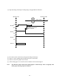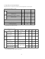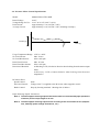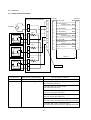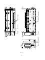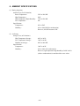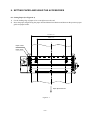
1
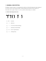
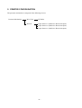
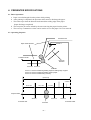
PRESENTER UNIT PR921-24-A SPECIFICATION MANUAL NOTICE • All rights reserved. Reproduction of any part of this manual in any form whatsoever, without STAR’s express permission is forbidden. • The contents of this manual are subject to change without notice. • All efforts have been made to ensure the accuracy of the contents of this manual at the time of going to press. However, should any errors be detected, STAR would greatly appreciate being informed of them. • The above notwithstanding, STAR can assume no responsibility for any errors in this manual. Copyright 2002 Star Micronics Co., LTD. CONTENTS 1. GENERAL DESCRIPTION ................................................................................................................ 1 1.1 Model Name Display Directions ............................................................................................. 1 2. PRINTER CONFIGURATION ........................................................................................................... 2 3. PAPER SPECIFICATIONS (HEAT SENSITIVE PAPER) ............................................................. 3 4. PRESENTER SPECIFICATIONS ...................................................................................................... 4 4.1 4.2 4.3 4.4 4.5 Basic Operations ...................................................................................................................... 4 Operating Sequence ................................................................................................................. 4 Paper Detector General Specifications .................................................................................... 8 Presenter Motor General Specifications .................................................................................. 9 Connector ............................................................................................................................... 10 5. EXTERNAL SPECIFICATIONS ..................................................................................................... 12 6. AMBIENT SPECIFICATIONS ......................................................................................................... 15 7. RELIABILITY SPECIFICATIONS ................................................................................................. 16 8. SETTING PAPER ............................................................................................................................... 17 8.1 8.2 Setting Paper .......................................................................................................................... 17 Using the Accessories (Weight Shaft and Loop Guide) ........................................................ 18 9. RECOVERING FROM ERRORS (PAPER JAMS) ....................................................................... 21 10. PRECAUTIONS REGARDING OUTER COVER DESIGNS ...................................................... 23 11. MAINTENANCE ................................................................................................................................ 25 12. OTHER PRECAUTIONS .................................................................................................................. 26 12.1 12.2 Precautions in Handling ......................................................................................................... 26 Precautions Relating to Safty ................................................................................................. 26 1. GENERAL DESCRIPTION The PR921 is a paper (receipts, etc.) discharging device that uses a built-in thermal printer system employed in electronic devices such as game machines, ATM and unmanned information kiosk terminals, etc. This model carries a paper (receipts, etc.) recovery function after discharge, as a standard. 1.1 Model Name Display Directions P R 1 9 2 1 2 3 4 - 2 4 - 5 1 PR : 2 9: 900 Series 3 2: No cutter, horizontal discharge 4 1: Standard (Used with TMP) 5 24 : DC 24 V Specifications 6 A: Sold Separately A 6 Presenter –1– 2. PRINTER CONFIGURATION The presenter mechanism is composed of the following devices. Presenter Mechanism Drive Unit PF Roller Detector Paper Detector 1 (Reflective Photo-interrupter) Paper Detector 2 (Reflective Photo-interrupter) Paper Detector 3 (Reflective Photo-interrupter) –2– 3. PAPER SPECIFICATIONS (HEAT SENSITIVE PAPER) (1) Paper Width : 79.5 ±0.5 mm to 111.5 ±0.5 mm (2) Allowable Sheet Length : 75 to 300 mm (3) Recommended Heat Sensitive Paper : According to product specifications for TMP942-24-A. (4) Paper Thickness : 0.065 mm to 0.150 mm (5) Shaft Core Diameter : When paper thickness is Min. 0.065 mm to 0.10 mm Shaft core inner diameter: Min. 25.4 ±1 mm; Shaft core outer diameter: Min. 31.4 ±1 mm When paper thickness is Min. 0.10 mm to 0.15 mm Shaft core inner diameter: Min. 50.8 ±1 mm; Shaft core outer diameter: Min. 56.8 ±1 mm (6) Paper Curl Direction : Set the paper so that the printing side is facing the outside when taken up on the roll. Note 1: Paper jams can occur if paper outside of the specifications describe above is use. (7) Non-printing Region on Back Side : 25 mm Center of presenter paper discharge outlet 10 mm The front side of the paper is the printing surface. Paper discharge direction Paper back side Non-printing region (Back side) 79 mm (Minimum paper width) 112 mm (Maximum paper width) Note 2: When using paper outside of the specifications describe above, the paper detector(sensor) may mis-detect the paper or may not detect the paper at all. –3– 4. PRESENTER SPECIFICATIONS 4.1 Basic Operations a. Paper is not discharged from the printer while printing. b. After printing is completed, the presenter roller rotates to discharge the paper. c. The roller stops when the detector has detected the trailing edge of the paper. (Paper discharge completed) d. The next print job can be started by the user removing the paper from the printer. e. The recovery command or a timer can be used to recover the paper if it is not removed. 4.2 Operating Sequence Presenter Inlet Sensor 1 Paper Feed Direction Presenter Outlet Recovery Direction Sensor 3 Sensor 2 PF Roller Sensor 1: Sensor for detecting leading edge and trailing edge of paper. Sensor 2: Sensor for detecting leading edge of paper. Sensor 3: Sensor for determining recovery (63.6 mm) 7.8 mm 4.9 mm 30. 6 mm 13.1 mm 7.2 mm Paper Position Sensor 2 Sensor 1 Presenter Inlet PF Roller –4– Sensor 3 Presenter Outlet (1) Paper is discharged and the trailing edge of the paper is stopped in front of the PF roller. Presenter Inlet Presenter Outlet Paper Position 200 ms CW 2 DC Motor CCW 4 Terminal Shorted and Motor Stopped ON Sensor 1 1 OFF ON Sensor 2 3 OFF Sensor 3 1 2 3 4 No Discrimination Sensor 1 detects leading edge of paper and sensor 1 turns ON. Sensor 1 turns ON, DC motor starts rotating clockwise. Sensor 2 detects leading edge of paper and sensor 2 turns ON. Sensor 2 turns ON, DC motor is braked for 200 ms and stopped. –5– (2) Paper Discharge Until Paper Trailing Edge is Stopped Before PF Roller Presenter Inlet Presenter Outlet Paper Position CW DC Motor 200 ms 5 8 CCW 7 Terminal Shorted and Motor Stopped ON 6 Sensor 1 OFF ON Sensor 2 OFF Sensor 3 5 6 7 8 No Discrimination DC motor rotates clockwise by the paper discharge instruction. Sensor 1 detects trailing edge of paper and sensor 1 turns OFF. Sensor 1 turns OFF, paper is fed 1.2 mm. After feeding paper 1.2 mm, DC motor is braked for 200 ms and stopped. Note: The amount of time required for feeding paper 1.2 mm in step 7, above, is logically 4 ms with a paper discharge speed of 300 m/s. –6– (3) Paper Recovery Operation If the sensor 2 and sensor 3 detection signals are ON after a determined amount of time has passed, the paper recovery operation is performed. Presenter Outlet Presenter Inlet Paper Position 1s CW DC Motor 9 200 ms 12 CCW Terminal Shorted and Motor Stopped ON Sensor 1 OFF ON 11 Sensor 2 OFF ON Sensor 3 10 OFF 26 ms Sensor 3 turns OFF, then, if sensor 2 turns OFF, it is determined that the paper has been recovered. Under all other conditions, it is considered that paper has been pulled out. 9 0 A B DC motor rotates counterclockwise by the paper recovery instruction. Sensor 3 detects trailing edge of paper and sensor 3 turns OFF. Sensor 2 detects trailing edge of paper and sensor 3 turns OFF. 1 second after sensor 2 turns OFF, DC motor is braked for 200 ms and stopped. Note: The distance between sensor 2 and sensor 3 is 7.8 mm. Therefore, the amount of time required for sensor 2 to turn OFF after sensor 3 turns OFF is 26 ms. It is necessary to enable detection in that amount of time. –7– 4.3 Paper Detector General Specifications The paper detector is composed of a reflective sensor and generates a set/reset signal. Absolute Maximum Rating (at 25°C) Light Recep- Light Emittion Side ting Side Items Symbol Rating Units Reverse Voltage VR 6 V Forward Current IF 50 mA Tolerance Loss PD 75 mW Voltage Between Collector - Emulator VCE0 35 V Collector Current IC 20 mA Collector Loss PC 75 mW Total Tolerance Loss Ptot 100 mW Operating Temperature Topt -25 to +85 °C Storage Temperature Tstg -40 to +100 °C * Soldering Temperature Tsol 260 °C * Soldering Time: Within 5 seconds Joining Characteristics Output Char- Input Characteristics acteristics Electrical Characteristics (at 25°C) Item Symbol Forward Voltage VF IF = 20 mA Reverse Current IR VR = 3 V Dark Current Optical Current ICEO Conditions MIN VCE = 20 V TYP MAX Units 1.2 1.4 V 10 µm 100 nA 3.0 mA 500 nA 1 IC IF =20 mA, VCE =5V Ileak IF =20 mA, VCE = 5V Response Time (Rise) tr VCE=2V, IC=100 µA RL =1000 Ω , D =4 mm 50 150 µs Response Time (Fall) tf (*2) 50 150 µs * 1 Leaked Current *1: No reflective material. *2: D is the thickness of the reflective mirror glass. –8– 1.0 4.4 Presenter Motor General Specifications Model: Rated Voltage: Voltage Range for Use: Peak Current: Average Current: Mabuchi Motor FK-180SH 24.0 V 21.6 V to 26.4 V (24.0 V ±10%) Approximately 1.0 A (24 VDC, 25°C) Approximately 0.2 A (24 VDC, 25°C, including at startup.) Current (A) Time (T) Usage Temperature Range: No Load Current: No Load Revolutions: Rated Load Current: Rated Load Revolutions: Direction of Rotation: DC Motor Drive Speed Control: Drive and Control: Brake Control: -15°C to +60°C Max. 30 mA 6600 ± 850 rpm Max. 110 mA 5000 ± 650 rpm At Discharge: CW (Clockwise direction when looking from the motor output shaft.) At Recovery: CCW (Counterclockwise when looking from the motor outputshaft.) None Voltage (24.0 V) is applied to the DC motor when stopped to start it. Stops by shorting terminals. Shorting time is 200 ms. Paper Discharge Speed: 300 mm/sec Note 1: The above paper discharge speed reflects the value for recommended paper (thickness of 65 mm) and a receipt length of 75 mm. Note 2: The above paper discharge speed varies according to the environment of use (temperature, humidity, power voltage fluctuations, etc.). –9– 4.5 Connector 4.5.1 Paper Detector and Motor Connector 2 Presenter Intermediate Board 8 + 8 7 7 6 6 5 5 Connector 2 Pin #8: GND Black Pin #7: Sensor 3 Detection signal Black 8 7 DC Motor Sensor PCB 330 Ω Sensor 3 GP2S40J Sensor PCB 330 Ω Sensor 2 4 4 3 3 2 2 1 1 Pin #6: Motor(+) Black Pin #5: Motor(-) Black Pin #4: Sensor 2 Detection signal Black Pin #3: GND Black Pin #2: Sensor 1 Detection signal Black Pin #1: +3.3 V White 6 5 4 3 2 1 GP2S40J 350 mm Sensor PCB 330 Ω Sensor 1 Connector 1 GP2S40J Connector No. Connector 1 Connector 2 Manufacturer and Model No. Corresponding Connectors JST S 8B-PH-K-S (Side Type) JST PHR-8 (Housing) JST PHR-8 (Housing) JST S 8B - PH - K - S (Side Type) (Post standard with base) JST B 8B - PH - K - S (Top Type) (Post standard with base) JST S 8B - PH - KL (Side Type) (Post low check type with base) JST B 8B - PH - KL (Top Type) (Post low check type with base) JST S 8B - PH - SM2 - TB (Side Type) (Post with surface mount type base:with support bracket) JST B 8B - PH - SM2 - TB (Top Type) (Post with surface mount type base: withsupport bracket) – 10 – VM 4.5.2 Example Circuit B8B-PH-K-S 7 TA8428K VCC 1 PRM1 PRM2 2 VDD: 3.3V HS601 5 6 6 GND 4 10K VDD: 3.3V 8 2 4 7 HS601 R VDD: 3.3V 0R 4.7K PRS1ADJ VDD: 3.3V VDD: 3.3V 10K 3 2 PRS1 - 4 + 5 HA1 7339 M-GND 68K C 12 VDD: 3.3V 0.022U 0.1U 10K 2 1 3 GND VR_4.7K 0R 4.7K GND GND GND R VDD: 3.3V 4.7K PRS2ADJ 10K VDD: 3.3V 1 PRS2 6 HA1 7339 7 + 68K C 0.1U VDD: 3.3V 10K 2 1 3 GND VR_4.7K 0R 4.7K GND GND R VDD: 3.3V PRS3ADJ VDD: 3.3V PRS3 4.7K 10K 14 8 HA1 7339 9 + VDD: 3.3V 68K C 0.1U 10K GND 2 1 3 VR_4.7K 4.7K GND Note: VCC MM+ GND SIG 1 SIG 2 SIG 3 M-GND 4.7K PRS0 1 47U_35V 3 IN1 OUT A IN2 OUT B + GND Parts marked with an asterisk are not mounted. – 11 – 0R 3 GND 5. EXTERNAL SPECIFICATIONS (1) External Dimensions See Figure 5-1 (2) Weight: 285 ±10g (Excluding peripheral devices) (3) External View See Figure 5-2 – 12 – ✽✵✲✻ ✸✼ ✵✺✼✲✸ ✵✷✴ ✸✼ ✻✺✲✻ ✵✶✲✹ ✼ ✹✻ ✻✹ ✹✼ ✻ ✹✼ ✹✻ Unit: mm Figure 5-1 – 13 – Figure 5-2 – 14 – Motor Paper Detector Motor Motor Rear Guide Paper Detector Rear Guide Paper Detector 6. AMBIENT SPECIFICATIONS (1) During Operation Ambient Test (For Evaluation) Room Temperature : High Temperature : High Temperature/High Humidity : Low Temperature : Specifications Temperature : Humidity : (2) At Storage Storage Test (At Evaluation) High Temperature Storage : Low Temperature Storage : Humidity at Storage : Specifications Temperature : Humidity : 23°C at 50% RH 50°C 37°C at 85% RH 0°C 0°C to 50°C 10% to 80% RH (No condensation) However, 80% RH assumes 34°C. 60°C at 96 Hr -20°C at 96 Hr 40°C at 90% RH -20°C to 60°C 10% to 90% (No condensation) However, high temperature/high humidity of 40°C at 90% (with no condensation) is considered the worst values. – 15 – 7. RELIABILITY SPECIFICATIONS (1) Life Presentation System: 1 million times Note 1: If not using our recommended paper type, reliability cannot be guaranteed. Therefore, you should always use the recommended paper type. Note 2: This reliability is guaranteed for receipt lengths of 100 mm or less. (2) Vibrations/Shocks from Drops (In the order of drop, vibrations) 1 Drop Shock Test Height of Drop : 1 angle, 3 corners: 85 cm 6 surfaces: 100 cm Direction of Drop : 1 angle; 3 corners; 6 surfaces Number of Drops : Once each time (total of 10 drops) Packing Status : Minimum Packing Status 2 Vibration Test Direction of Vibration : Vibration Frequency : Sweep Time : Vibration Acceleration Speed : Charging Time : Packing Status : Total Vibrations : XYZ 10 Hz to 55 Hz to 10 Hz 1 minute 0.3 to 9.3 G One Direction Two Hours (Total Six Hours) Minimum Packing Status Constant at 1.54 mm – 16 – 8. SETTING PAPER AND USING THE ACCESSORIES 8.1 Setting Paper (See Figure 8-1) 1) Cut the leading edge of paper to be set straight across the end. 2) Insert the paper straight along the paper mounted thermal mechanism and between the presenter paper guide and paper holder. 111.5±0.5 mm 79.5±0.5 mm Paper Holder Paper Guide Paper Eject Direction Figure 8-1 – 17 – 8.2 Using the Accessories (Weight Shaft and Loop Guide) • Paper thickness: Min. 0.065 to Max. 0.10 mm. (See Figure 8-2) 1) No shaft is used so fasten the 3 hooks in the 3 positions on the rear guide so that they do not get lost. 2) Fasten the loop cutter to the cutter with the 2 accessory screws. 1. Position the loop guide and cutter in positioners 1 and 2. 2. Tighten the screw next to the positioner 1. 3. While pulling the next loop guide in the direction of the arrow, tighten the screw next to the positioner 2 so that it does not flow therebetween the cutter (see Fig. 8-3) 1 2 Paper Holder 3 Rear Guide Hook Hook Shaft Hook Screw TAT 3-6 CT-FL Screw TAT 3-6 CT-FL Cutter Loop Guide Positioner 2 Positioner 1 Figure 8-2 – 18 – 3) Rotate the paper holder and set after checking that it does not interfere with the loop guide. Note: Floating therebetween the cutter can occur because of deformation in the loop guide caused by sudden environmental changes. (See fig. 8-3) If that should occur, follow the directions above for the mounting of the loop guide and remount it so that it does not float. Floating [ If Floating Occurs Between the Loop Guide and Cutter ] Cutter Loop Guide Figure 8-3 – 19 – • Paper thickness: Min. 0.10 to Max. 0.15 mm. (See Figure 8-4) 1) Fasten the shaft with the left and right hooks positioned on the Paper Holder. 2) Check that the shaft is securely fastened to the Paper Holder hooks to set it. Note 1: The 2 positions of the Paper Holder should be adjusted for the thickness of the recording paper, the length thereof and the environment of use. Note 2: The loop guide is not used, so store it so that it will not get lost. Paper Holder 1 2 Hook Hook Shaft 3 Figure 8-4 – 20 – 9. RECOVERING FROM ERRORS (PAPER JAMS) Remove jammed paper according to the directions shown in Figure 9-1 and 9-2 to recover from non-recoverable paper jams. When doing so, always verify that the power has been turned OFF. (Procedure 1) 1) Rotate the knob in the clockwise or counterclockwise direction. 2) Remove the jammed sheet from where it is easiest to remove. (Paper inlet, discharge outlet, of the lower recovery space) Jammed Paper Inlet Rotate Discharge Outlet Knob Remove jammed paper from the lower space. Figure 9-1 – 21 – (Procedure 2: When Paper Cannot be Removed with Procedure 1) 1) Remove the screws on both sides of the presenter, shown in the figure below. 2) Rotate the rear guide and remove the jammed paper. 3) After removing the jammed paper, reverse the procedure 2), then fasten the screws in their original positions. Note: When fastening the screws in procedure 3), be careful not to pinch the wires shown in the figure below. Rear Guide Rear Guide Rotate Rotate Wires Screw: TAT 2.6 FC-06.0 FP Screw: TAT 2.6 FC-06.0 FP Left side Right side Figure 9-2 – 22 – 10. PRECAUTIONS REGARDING OUTER COVER DESIGNS To prevent jams at the presenter discharge outlet, consider designing the casing so that recording paper does not enter between the presenter unit and the case. 1 Gap of *1 must be a maximum of 1 mm. (See Figure 10-1) 2 The dimensions of *2 must be larger than the presenter discharge outlet (2 mm), but it should be small enough that it does not block the paper discharge outlet.(See Figure 10-1) If it is too large, interfering light (from the sun, etc.) will enter from outside of the apparatus from the recording paper outlet causing the paper detectors (sensors) to mis-operate, so do not make them too large. 1) The casing for the recording paper discharge outlet should have an outlet portion established such as *3 so that coins and clips do not fall into the casing. (See Figure 10-1) 2) Storage space for the recovery of recording paper should consider the length of the recording paper and degree of curling to all plenty of space. It is recommended to ensure approximately 100 mm or more space for storage depth. (See Figure 10-2) Case Presenter *2 *3 *1 Figure 10-1 – 23 – Mechanism Presenter Depth: Max. Approx. 100 mm Figure 10-2 – 24 – Allow for plenty of space. Storage Space 11. MAINTENANCE Perform the following maintenance periodically. Maintenance Periods: Every six months or after a million lines of printing. Location of Maintenance: Each detector and the vicinity Content of Maintenance: Clean away and paper dust or dirt and dust adhering to the detectors in the presenter. Note 1: Note 2: Always verify that the power supply has been turned OFF when performing maintenance on the presenter. Remove the two screws on both sides of the presenter, as shown in Figure 11, and rotate the rear guide upward to remove any dust and dirt on the paper detector in the presenter. After performing maintenance, return the rear guide to its original status and tighten the screws. When doing so, do not allow the screws to catch on the wires in the Figure 11. Screw: TAT 2.6 FC-06.0 FP Screw: TAT 2.6 FC-06.0 FP Wire Rear Guide Rotate Rear Guide Rotate Paper Detector Left side Right side Figure 11-1 – 25 – 12. HANDLING THE PRESENTER 12.1 Precautions in Handling 1) Do not store or use the printer in locations that are dusty, oily or exposed to metallic dust. 2) Do not apply an unreasonable amount of force on the body. (This can disfigure the frame and lead to the printer not functioning properly.) 3) Avoid sudden changes even if the ambient temperature and humidity are within standard conditions. Allow the printer to sit in its new environment for at least 30 minutes before use in the event there has been a sudden change. 4) Do not use the printer in an environment where condensation has formed. If condensation should form, absolutely never turn ON the power until the condensation has dried. 5) The setup angle for the presenter should be a maximum of ±5°, as shown in Figure 12. 6) Paper transport and life cannot be guaranteed when using recording paper other than what is recommended. 7) Be careful not to allow foreign matter to adhere to the recording paper. 8) Be careful not to apply an excess amount of force on the cable connectors. 9) When closing the presenter from an open state, verify that the presenter is securely locked before operating. 12.2 Precautions Relating to Safety 1) After operation is completed, the surface of the motor can be very hot, so be careful never to touch it directly with your bare hands. 2) When the presenter is operating, never touch the rotating members, such as the gears. 3) Handle the presenter engine (the metallic portions) carefully because they can cause serious injury. 4) To perform maintenance on the presenter, always verify that the power supply has been turned OFF. – 26 – Max.5° Max.5° Figure 12 – 27 – ELECTRONIC PRODUCTS DIVISION STAR MICRONICS CO., LTD. 536 Nanatsushinya, Shimizu, Shizuoka, 424-0066 Japan Tel : 0543-47-0112 Fax: 0543-48-5013 OVERSEAS SUBSIDIARY COMPANIES STAR MICRONICS AMERICA, INC. 1150 King Georges Post Road, Edison, NJ 08837-3729 U.S.A. Tel : 732-623-5555 Fax: 732-623-5590 http://www.starmicronics.com STAR MICRONICS U.K. LTD. Star House, Peregrine Business Park, Gomm Road, High Wycombe, Bucks, HP13 7DL, U.K. Tel : 01494-471111 Fax: 01494-473333 http://www.starmicronics.co.uk Please access the following URL http://www.star-micronics.co.jp/service/frame_sp_spr_e.htm for the lastest revision of the manual. Distributed by REV. 0.01 2002.11.10 Printed in Japan, 80874475