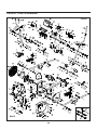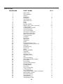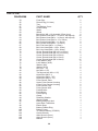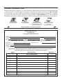
1
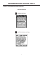
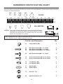
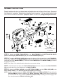
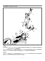
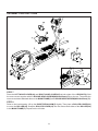
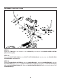
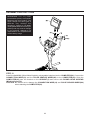
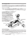
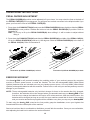
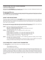
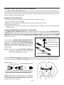
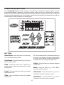
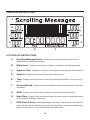
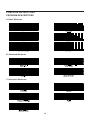
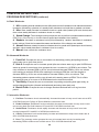
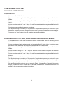
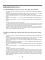
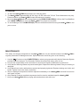
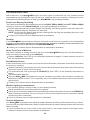
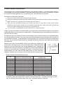
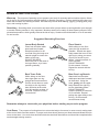
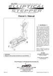
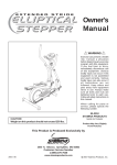
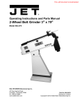
Owner's
Manual
WARNING
Exercise can present a health
risk. Consult a physician
before beginning any exercise
program with this equipment.
If you feel faint or dizzy,
immediately discontinue use
of this equipment. Serious
bodily injury can occur if this
equipment is not assembled
and used correctly. Serious
bodily injury can also occur if
all instructions are not
followed. Keep others and
pets away from equipment
when in use. Always make
sure all bolts and nuts are
tightened prior to each use.
Follow all safety instructions in
this manual.
When calling for parts or
service, please specify the
following number.
CAUTION:
Weight on this product should not exceed 300 lbs.
This Product is Produced Exclusively by
75-2000
Pat. Nos. 5,779,598 &
6,063,008
Other patents applied &
are pending
MADE IN TAIWAN
Product May Vary Slightly
From Pictured.
2040 N. Alliance, Springfield, MO 65803
Customer Service Number
1 (800) 375-7520
2007, 11
www.staminaproducts.com
2007 Stamina Products, Inc.
TABLE OF CONTENTS
Page
Safety Instructions
Before You Begin
Equipment Warning & Notice Labels
Hardware Identification Chart
Assembly Instructions
Set Up Instructions
Operational Instructions
Computer Instructions
Storage
Page
2
4
5
6
7
12
13
17
23
Maintenance
Troubleshooting
Conditioning Guidelines
Warm-Up and Cool-Down
Warranty
Product Parts Drawing
Parts List
Fax/Mail Ordering Form
23
24
25
26
27
28
29
31
SAFETY INSTRUCTIONS
WARNING: To reduce the risk of serious injury, read the following Safety Instructions before
using the Avari GX8 Elliptical Trainer, hereafter referred as the Avari GX8.
1.
2.
3.
4.
5.
6.
7.
8.
9.
10.
11.
12.
13.
14.
15.
16.
17.
18.
19.
20.
Read all warnings posted on the Avari GX8.
Read this owner's/user's manual and follow it carefully before using the Avari GX8.
We recommend that two people be available for assembly of this product.
Keep children away from the Avari GX8. Do not allow children to use or play on the Avari GX8.
Keep children and pets away from the Avari GX8 when it is in use.
It is recommended that you place this exercise equipment on an equipment mat.
Set up and operate the Avari GX8 on a solid level surface. Do not position the Avari GX8 on
loose rugs or uneven surfaces.
Make sure that adequate space is available for access to and around the Avari GX8.
Inspect the Avari GX8 for worn or loose components prior to use.
Tighten/replace any loose or worn components prior to using the Avari GX8.
Consult a physician prior to commencing an exercise program. If, at any time during exercise, you
feel faint, dizzy, or experience pain, stop and consult your physician.
Follow your physician's recommendations in developing your own personal fitness program.
Always choose the workout which best fits your physical strength and flexibility level. Know your
limits and train within them. Always use common sense when exercising.
Do not wear loose or dangling clothing while using the Avari GX8.
Never exercise in bare feet or socks; always wear correct footwear, such as running, walking, or
crosstraining shoes. Be sure that they fit well, provide foot support and feature non-skid rubber
soles.
Be careful to maintain your balance while using, mounting, dismounting, or assembling the Avari
GX8, loss of balance may result in a fall and serious bodily injury.
Keep both feet firmly and securely on the pedal caps while exercising.
The Avari GX8 should not be used by persons weighing over 300 pounds.
The Avari GX8 should be used by only one person at a time.
The Avari GX8 is for consumer use only. It is not for use in public or semipublic facilities.
Use two people to move the Avari GX8.
WARNING: Before starting any exercise or conditioning program you should consult with your personal
physician to see if you require a complete physical exam. This is especially important if you
are over the age of 35, have never exercised before, are pregnant, or suffer from any
illness. READ AND FOLLOW THE SAFETY PRECAUTIONS. FAILURE TO FOLLOW
THESE INSTRUCTIONS CAN RESULT IN SERIOUS BODILY INJURY.
2
CALL US FIRST
THANK YOU FOR PURCHASING THE
Avari GX8 Elliptical Trainer
To help you get started, we have pre-assembled most of your
Avari GX8 Elliptical Trainer at the factory with the exception
of those few parts left unassembled for shipping purposes.
Simply follow the few assembly instructions set forth in this manual.
With regular workouts you will be getting your body into shape
and on your way to achieving a happier and healthier lifestyle.
Should you have any questions,
please call our Customer Service Department toll-free number,
1 (800) 375-7520
Monday - Thursday, 7:30 A.M. - 5:00 P.M. Central Time.
Friday, 8:00 A.M. - 3:00 P.M., Central Time.
TELEPHONE
FAX
ONLINE
MAIL
CUSTOMER SERVICE
Tel: 1 (800) 375-7520
CUSTOMER SERVICE
Fax: (417) 889-8064
CUSTOMER SERVICE
[email protected]
[email protected]
www.staminaproducts.com
STAMINA PRODUCTS, INC.
ATTN: Customer Service
P.O. Box 1071
Springfield, MO. 65801-1071
3
BEFORE YOU BEGIN
Although Stamina constructs its products with the
finest materials and uses the highest standards of
manufacturing and quality control, there can
sometimes be missing parts or incorrectly sized
parts. If you have any questions or problems with
the parts included with your Avari GX8, please do
not return the product. Contact us FIRST!
If a part is missing or defective, please call us toll
free at 1-800-375-7520 (in the U.S.). Our Customer
Service Staff is available to assist you from 7:30 A.M.
to 5:00 P.M. (Central Time) Monday through Thursday
and 8:00 A.M. to 3:00 P.M. (Central Time) on Friday.
If you would like to contact us online, go to our
website at www.staminaproducts.com and access the
Customer Service section.
Be sure to have the name and model number of
the product available when you contact us.
Thank you for choosing the Avari GX8. We take
great pride in producing this quality product and hope
it will provide many hours of quality exercise to make
you feel better, look better and enjoy life to its fullest.
Yes, it's a proven fact that a regular exercise
program can improve your physical and mental
health. Too often, our busy lifestyles limit our time
and opportunity to exercise. The Avari GX8
provides a convenient and simple method to begin
your assault on getting your body in shape and
achieving a happier and healthier lifestyle.
Before reading further, please review the drawing
below and familiarize yourself with the parts that are
labeled.
Read this manual carefully before using the Avari
GX8.
ATTENTION: Use only NiMH
(Nickel Metal Hydride) rechargeable
batteries with this product. The
higher voltage from other types of
batteries may damage this
equipment. Failure to use NiMH
rechargeable batteries will void your
warranty and may result in damage
to your machine. Stamina is not
responsible for non-compliance with
correct battery usage.
Battery
Warning Label
Computer
Pulse Sensor
Tray
Handlebar
Handlebar
Rocker Arm
Upright
Pedal Divider
Left Pedal Arm
Pedal Cap
Warning Label
Crank Disc
Nose Covers
Roller Cover
Right Pedal Arm
Covers
Link
Rear Stabilizer
Pedal Cap
Main Frame
Wheel
THE FOLLOWING TOOLS ARE INCLUDED FOR ASSEMBLY :
Socket Wrench
Allen Wrench (5mm)
Allen Wrench (6mm)
4
EQUIPMENT WARNING & NOTICE LABELS
This chart is provided to help identify the warning & notice labels on the Avari
to familiarize yourself with all of the warning & notice labels.
Labels are actual size
W1
WARNING LABEL(95)
W2
BATTERY WARNING LABEL(96)
5
GX8. Please take a moment
HARDWARE IDENTIFICATION CHART
This chart is provided to help identify the hardware used in the assembly process. Place the washers, the
end of the bolts, or screws on the circles to check for the correct diameter. Use the small scale to check the
length of the bolts and screws.
3/16"
1/4"
5/16"
3/8"
1/2"
INCHES
0
1/2
1
1/2
2
1/2
3
1/2
4
1/2
5
1/2
6
in.
mm.
0
10
20
30
40
50
60
70
80
90
100 110 120
130 140 150
MILLIMETERS
6
8
10
length
12
NOTICE: The length of all bolts and screws except those with flat heads is
measured from below the head to the end of the bolt or screw.
Flat head bolts and screws are measured from the top of the
head to the end of the bolt or screw.
length
After unpacking the unit, open the hardware bag and make sure that you have all the following items.
Some hardware may be already attached to the part.
Part No. and Description
Qty
53
Clamp Washer (M6)
8
62
63
64
Bolt, Button Head (M6 x 1 x 12mm)
Bolt, Button Head (M6 x 1 x 16mm)
Bolt, Button Head (M10 x 1.5 x 25mm)
4
8
2
65
Bolt, Socket Head (M6 x 1 x 12mm)
8
70
71
Screw, Round Head (M5 x 0.8 x 15mm)
Screw, Round Head (M5 x 0.8 x 35mm)
75
76
Lock Washer (M6)
Lock Washer (M10)
8
2
77
78
Washer (M6)
Washer (M10)
4
6
79
Nut (3/8" - 16)
3
84
Nylock Nut (M10 x 1.5)
4
6
12
5
ASSEMBLY INSTRUCTIONS
Place all parts from the box in a cleared area and position them on the floor in front of you. Remove all
packing materials from your area and place them back into the box. Do not dispose of the packing materials
until assembly is completed. Read each step carefully before beginning. If you are missing a part please
call our toll-free number for assistance 1 (800) 375-7520 or e-mail us at: [email protected]
L
Lift from the
Front Stabilizer
R
Make the tab face down
for assembly.
STEP 1: Attach the REAR STABILIZER(2) to the MAIN FRAME(1) with BUTTON HEAD BOLTS
(M10x1.5x25mm)(64), WASHERS(M10)(78), and LOCK WASHERS(M10)(76).
STEP 2: Thread the NUTS(3/8"-16)(79) all the way to the bottom of the threaded rod on the STANDS(59).
Lift the front stabilizer on the MAIN FRAME(1) and place a temporary spacer (wood block or thick book)
under the front of the MAIN FRAME(1). Thread the three STANDS(59) into the MAIN FRAME(1). Remove
the temporary spacer.
NOTE: See page 12 for detailed leveling instructions to prevent rocking.
STEP 3: Make the tab in the edge of the OVAL ENDCAPS(58) face down, then press the OVAL ENDCAPS
(58) into both ends of the front stabilizer of the MAIN FRAME(1).
STEP 4: Attach the PEDAL CAP(29L) to the LEFT PEDAL ARM(6) and the PEDAL CAP(29R) to the
RIGHT PEDAL ARM( 7) with SOCKET HEAD BOLTS(M6x1x12mm)(65).
NOTE: It will be easier to attach the PEDAL CAPS(29L, 29R) to the PEDAL ARMS(6, 7) by raising the
PEDAL ARMS(6,7) and then attaching the PEDAL CAPS(29L, 29R). Please have a partner hold
the raised pedal arm as you attach the PEDAL CAPS(29L, 29R). This way you are not lying on the
floor trying to attach the PEDAL CAPS(29L, 29R).
7
ASSEMBLY INSTRUCTIONS
STEP 5
CAUTION: Be careful not to damage the BASE CONNECTION WIRE(18) and CONNECTION WIRE(19)
when assembling the UPRIGHT(3).
Attach the UPRIGHT(3) to the MAIN FRAME(1) with the NYLOCK NUTS(M10x1.5)(84) and WASHERS
(M10)(78). Plug the BASE CONNECTION WIRE(18) into the CONNECTION WIRE(19).
STEP 6
Connect the LINKS(36) to the ROCKER ARMS(4) at both sides with D-SHAPED SHAFT(42), WASHERS
(M6)(77), and BUTTON HEAD BOLTS(M6x1x12mm)(62).
8
ASSEMBLY INSTRUCTIONS
Slot
STEP 7
Place the LEFT NOSE COVER(34) and RIGHT NOSE COVER(35) at both sides of the UPRIGHT(3). Bolt
the nose covers together with the ROUND HEAD SCREW(M5x0.8x35mm)(71) on the top. Then slide the
nose covers down and attach them to the MAIN FRAME(1) with ROUND HEAD SCREW(M5x0.8x35mm)(71).
STEP 8
Refer to the inset drawing. Lift up the RIGHT PEDAL ARM(7) slightly. Then place a ROLLER COVER(33)
to cover the ROLLER(30). Snap the ROLLER COVER(33) into the slots at both sides of the ROLLER(30)
in the MAIN FRAME(1). Repeat on the left side.
9
ASSEMBLY INSTRUCTIONS
STEP 9
Attach the TRAY(56) to the bracket on the UPRIGHT(3) and secure with ROUND HEAD SCREWS
(M5x0.8x15mm)(70).
STEP 10
Attach the PIVOT ENDCAPS(51) to the PIVOT CUFF BUSHINGS(45) at both sides with ROUND HEAD
SCREWS(M5x0.8x15mm)(70).
STEP 11
Slide the HANDLEBAR SLEEVE(52) onto the HANDLEBARS(5). Insert the HANDLEBARS(5) onto the
ROCKER ARMS(4) and secure with BUTTON HEAD BOLTS(M6x1x16mm)(63), CLAMP WASHERS(M6)
(53), and LOCK WASHERS(M6)(75). Slide the HANDLEBAR SLEEVE(52) down to cover the bolts on the
HANDLEBARS(5).
10
ASSEMBLY INSTRUCTIONS
ATTENTION: Use only NiMH
(Nickel Metal Hydride) rechargeable
batteries with this product. The
higher voltage from other types of
batteries may damage this
equipment. Failure to use NiMH
rechargeable batteries will void your
warranty and may result in damage
to your machine. Stamina is not
responsible for non-compliance with
correct battery usage.
STEP 12
Install four AA NiMH (Nickel Metal Hydride) rechargeable batteries into the COMPUTER(20). Connect the
CONNECTION WIRE(19) and the PULSE SENSOR WIRES(89) to the COMPUTER(20). Slide the
COMPUTER(20) onto the bracket on the UPRIGHT(3) and secure with ROUND HEAD SCREWS
(M5x0.8x15mm)(70).
CAUTION: Be careful not to damage the CONNECTION WIRE(19) and PULSE SENSOR WIRES(89)
when attaching the COMPUTER(20).
11
SET UP INSTRUCTIONS
Place the Avari GX8 in the area where it will be used. It is recommended that the Avari GX8 be placed
on an equipment mat. The maximum usage dimensions of Avari GX8 are approximately 99 1/4" long x
25 5/8" wide x 64 7/8" tall. (These dimensions may vary up to one inch.) An area 4 feet wide x 9 feet long is
required for safe operation of the Avari GX8. Make sure that adequate space is available for access to and
passage around the Avari GX8.
LEVELING: Adjust the STANDS(59) under the MAIN FRAME(1) so that the Avari GX8 sits on the floor
without rocking. Refer to the instructions below the illustration.
MOVING: Move the Avari GX8 with the moving wheels on the REAR STABILIZER(2). Lift from the
Front Stabilizer of the MAIN FRAME(1). Two people are required to move the Avari GX8.
To level the Avari GX8, first screw the STAND(59) located in
the middle of the MAIN FRAME(1) all the way up into the
MAIN FRAME(1) so that it is not touching the floor.
Adjust the four STANDS(59) on each of the four
corners, two under REAR STABILIZER(2) and
two under the front of the MAIN FRAME(1).
When all four are adjusted and the Avari GX8
is stable, tighten the NUTS(3/8"-16)(79) against
the MAIN FRAME(1) and REAR STABILIZER(2)
to lock the STANDS(59) into position.
While you are adjusting these four STANDS(59),
the one STAND(59) located in the middle of the
MAIN FRAME(1) must not be in contact with the floor.
Only after the Avari GX8 has been stabilized with
the four STANDS(59) on the corners will you
position the middle STAND(59) so it is in
contact with the floor to provide extra
stability for the MAIN FRAME(1).
Lift up from the Front
Stabilizer for moving.
Equipment Mat
FUNCTION INSPECTION:
Visually inspect the Avari GX8 to verify that assembly is as shown in the above illustration. Check the
function of the Avari GX8. Stand on the foot pedals and place your hands at a comfortable position on the
handlebars. Slowly move your highest foot forward and follow the natural path of the machine. Turn the
crank slowly through one complete revolution to verify that the drive train functions properly. Use the "Quick
Start" and "+/-" buttons on the COMPUTER(20) to select a program and verify that the Generator System
provides different tensions. Refer to the COMPUTER INSTRUCTIONS on pages 17 to 22.
CAUTION: Locate and read the WARNING LABEL(95) on the Avari
the WARNING LABEL(95).
12
GX8. Make sure that all users read
OPERATIONAL INSTRUCTIONS
PEDAL DIVIDER ADJUSTMENT
The PEDAL DIVIDER(90) position can be adjusted to fit your shoes. You may select the front or the back of
the PEDAL CAPS(29) for foot placement. You will have less vertical movement in the elliptical stride if you
place your feet at the front of the PEDAL CAPS(29).
1. Press down the PUSH BUTTON(91) and press the PEDAL DIVIDER(90) down slightly to slide the PEDAL
DIVIDER(90) to new position. Release the button to lock the PEDAL DIVIDER(90) in position. Refer to
illustration A.
HINT : Do not try to lift up the PEDAL DIVIDER(90) when sliding it. It will be easier to adjust without
lifting it.
2. Press down the PUSH BUTTON(91) and slide the PEDAL DIVIDER(90) to middle of the PEDAL CAP(29).
Lift up the PEDAL DIVIDER(90) and turn it 180 degrees. Slide the PEDAL DIVIDER(90) to the back of
the PEDAL CAP(29). Refer to illustration B.
Illustration A) PEDAL DIVIDER(90) at front
Illustration B) PEDAL DIVIDER(90) at back
EXERCISE WORKOUT
Your Avari GX8 is self powered meaning the pedaling action of your workout powers the computer
monitor no electric power source or cords are needed. The four AA rechargeable NiMH (Nickel Metal
Hydride) batteries that are included serve as your backup power source. Use only NiMH (Nickel Metal
Hydride) rechargeable batteries with this machine. Failure to do so will void your warranty and may result in
damage to your machine.
NOTE: These rechargeable batteries only hold their charge for three to four weeks after fully charged;
therefore, the batteries will not be charged when you assemble and use your Avari GX8 for the
first time so to charge the batteries will require a 30 minute workout. After that initial workout, the
batteries will be charged (as long as you don't let your machine remain idle for three to four weeks)
and your monitor and workout programs will be available every time you step on your Avari GX8.
To start using the Avari GX8, stand on the foot pedals, grasp the handlebars, move your highest foot
forward and follow the natural path of the machine.
Start at a load level that is comfortable to familiarize yourself with the machine. Once you are comfortable,
start adjusting the load level to achieve the workout desired.
13
OPERATIONAL INSTRUCTIONS (continued)
Load Level Adjustment
The load level of Avari GX8 can be changed at any time during your workout. Adjusting the load level will
allow you to increase or decrease your intensity level.
Forward and Reverse
The Avari GX8 can be used in the forward and reverse direction to vary the muscles that you work out.
This will also vary your workout helping you to stay motivated. To change directions, simply slow the pedals
down until they stop and switch directions.
HEART RATE MONITORING
To get the maximum benefit from your Avari GX8 workout it is important that you exercise within your
target heart rate zone for at least 20 minutes. Research has shown that working out below your target heart
rate zone won't burn fat or improve your cardiovascular fitness, and working above your target heart rate
zone is also counter productive.
Everyone has their own target heart rate zone and exercising within that zone should be your goal every
time you work out. Finding your personal target heart rate zone is calculated by:
STEP 1: Find your maximum heart rate with this simple formula:
220 - Age = predicted maximum heart rate
Example: A 40-year-old would have a predicted maximum heart rate of
180 beats per minute, 220 - 40 = 180.
STEP 2: Your target heart rate zone is a range that is 55% to 90% of your
maximum heart rate.*
Predicted Maximum Heart Rate x .55 = lower end of target heart rate zone
Predicted Maximum Heart Rate x .90 = upper end of target heart rate zone
Example: A 40-year-old would have a Target Heart Rate Zone of 99 to
162 beats per minute; 180 x .55 = 99.
180 x .90 = 162.
NOTE:
See page 24 of this Owner's Manual for more conditioning guidelines including a chart of target
Heart Rate Zones Estimated by Age.
* For cardiorespiratory training benefits, the American College of Sports Medicine recommends
working out within a heart rate range of 55% to 90% of maximum heart rate.
PULSE MONITOR V. HEART RATE TRANSMITTER
The Avari
GX8 can measure how hard you are exercising in two ways:
1. By measuring your pulse
2. By monitoring your heart rate
Your pulse is monitored by four Pulse Sensors that are built into both the left and right Hand Grips, two in
each grip. Your pulse reading gives you a snapshot of how hard your heart is working at that point in your
workout by measuring the number of heart beats per minute. Please note that pulse sensors provide less
accurate information than the heart rate transmitter and pulse sensors don't monitor your heart rate during
your entire workout; the heart rate transmitter does monitor your heart rate for the endurance of your
workout.
14
OPERATIONAL INSTRUCTIONS (continued)
The HEART RATE TRANSMITTER(97) worn around your chest sends your heart rate information to a
receiver in your computer monitor so your heart rate is tracked while you exercise. This is the most reliable
way to measure your heart rate to make sure you are exercising within your target heart rate zone so you
get the most out of your workout time.
Using the Pulse Sensors
To get the most accurate reading from the Pulse Sensors, follow these steps.
Dry your hands to prevent slipping.
Make sure both hands are in contact with all four sensors (two in each hand).
Grasp the sensors firmly.
Apply constant pressure to the sensors until you get a consistent reading on your computerized workout
console screen.
Using the Heart Rate Transmitter Chest Strap
The HEART RATE TRANSMITTER(97) worn around the chest is powered by a 3V LITHIUM BATTERY
(CR2032)(101) located in the center of the strap. Two electrodes on either side of the battery monitor your
heartbeat, and an adjustable elastic strap holds the transmitter in place. The receiver built into the Avari
GX8 picks up your heart rate from the HEART RATE TRANSMITTER(97) and displays it on the monitor
during your workout.
close
To assemble the HEART RATE TRANSMITTER(97),
insert the 3V LITHIUM BATTERY(CR2032)(101) as
shown in the illustration, place the BATTERY RUBBER
RING(99) and BATTERY COVER(100) properly into the
case, then close the cover, tightening it with a coin or
similar opener.
open
(100) Battery Cover
(99) Battery Rubber Ring
(101) 3V Lithium Battery
(97) Heart Rate Transmitter
NOTE: Make sure to close the BATTERY COVER(100)
very tightly as illustrated to prevent sweat and
moisture from damaging the battery.
(98) Elastic Strap
Attach the ELASTIC STRAP(98) by inserting the heart-shaped tabs through the openings in the transmitter
and twisting. Adjust the ELASTIC STRAP(98) to fit your chest snugly as shown in the illustration below.
(98) Elastic Strap
Heart-shaped Tab
(97) Heart Rate Transmitter
To ensure a secure connection above, be sure that the front
edge of the Heart-shaped tab is completely inside of the heartshaped opening on the HEART RATE TRANSMITTER(97).
NOTE: Apply water or conductive gel to moisten the
ribbed rubber area covering the electrodes. This ribbed
area must be wet and in contact with your chest skin to
properly detect your heart rate.
15
OPERATIONAL INSTRUCTIONS (continued)
Transmission LED Indicator
For checking operation of transmitter, the red LED indicator will flash indicating the transmitter is in operation.
Adjust the transmitter position to keep the LED indicator flashing consistently for accurate readings. (See
illustration below.)
LED Indicator
NOTE: If your heart rate is inconsistent or not tracking on your workout console, do the following:
Moisten the grooved electrode areas on the back of the chest strap again and make sure they
are in contact with the skin. Your skin may be dry when you begin your workout and the moisture
is necessary to ensure contact. As you sweat, contact will improve.
Tighten the elastic strap so it remains in place as you exercise. Movement of the electrodes will
result in inaccurate or erratic signal and readings.
Clean the electrodes as dirt can interfere with transmission. Use a mild soap and water and dry
with a soft towel.
Transmitter Care and Maintenance
Wash regularly with mild soap and water solution and dry with a soft towel being careful not to abrade
the electrodes.
Store in a cool, dry place. Make sure the electrodes aren't stored with any wet material and never store
a wet transmitter in non-breathable material like a plastic bag or sports bag.
Do not bend or stretch the transmitter.
16
COMPUTER INSTRUCTIONS
Your Avari GX8 Elliptical Trainer workout is controlled by an advanced computer system. Use the
pre-programmed Basic, Advanced or Interactive workout profiles to vary your workouts from session to
session, or use the Quick Start workout and set your own pace. Whatever workout you choose, the computer
monitor will track and display your time, distance, calories burned, and heart rate information to keep you
motivated and on track to achieve your fitness goals.
BUTTONS
Quick Start:
+/-: Press these buttons to increase/decrease your
time, level. You will also press any of these buttons
to select your desired workout profile when
prompted from the scrolling message center.
Press this button to start working
out in a manual workout profile.
Cool Down:
Press this button to go into a 'Cool
Down' workout profile.
Select:
Press this button to input the displayed
screen value.
Stop:
Press this button once to pause your
workout session. Press this button twice to reset
the computer.
Basic:
Press this button to go to the "Basic"
workouts selection window.
Level:
Press this button to select your desired
workout level 1-25.
Advanced:
Press this button to go to the
"Advanced" workouts selection window.
Time:
Press this button to select your desired
workout time.
Interactive:
Press this button to go to the
"Interactive" workouts selection window.
17
COMPUTER INSTRUCTIONS
A
B
I
C
H
D
G
E
F
LCD DISPLAY INSTRUCTIONS
A
Scrolling Message Center: Displays both user instructions and workout
parameters throughout the workout.
B
Watts/Level: Displays the amount of power or resistance level being exerted.
C
Segment Time: Displays the amount of time spent in each segment of the workout.
D
Calories: Displays the amount of kcal burned by the user.
E
Time: Displays the total amount of time used during the workout. Can count up or
down.
F
Distance/Speed: Displays both the distance traveled and the speed of the user
alternately.
G
RPM: Displays the user's actual number of pedal revolutions per minute.
H
Heart Rate: Displays the user's actual heart rate when using the heart rate sensor
or the included telemetry heart strap.
I
HR%/Time In Zone: Alternately displays the user's actual percent of achieved
heart rate goal and the total amount of time that the user is at their goal when using
the heart rate sensor or the included telemetry heart strap.
18
COMPUTER INSTRUCTIONS
PROGRAM DESCRIPTIONS
A. Basic Workouts
B. Advanced Workouts
C. Interactive Workouts
19
COMPUTER INSTRUCTIONS
PROGRAM DESCRIPTIONS (continued)
A. Basic Workouts
1. Hill: Increasing interval resistance levels (hills) that have brief resistance level reductions between
increases, followed by a plateau of a steady state resistance level and then a gradual cool-down.
2. Hike: Slow, steady increase in resistance levels to a peak value (based upon level chosen) and
then a slow steady decrease in resistance levels to a valley.
3. Speed Change: The message center prompts the user to perform increases and decreases in
RPM (every 30 seconds) to simulate interval speed and resistance level training.
4. Random: Increases in resistance levels (hills) followed by "random" decreases in resistance
levels (valleys). Both the increases/decreases and duration of the changes are random.
5. Ascent: Moderate, steady increase in resistance level to a peak value (based upon level chosen)
and then a slow steady decrease in resistance level to a valley.
6. Manual: User controls the resistance level.
B. Advanced Workouts
1. Push-Pull: Prompts the user to concentrate on alternately pushing and pulling with their
upper body over a given time period.
2. Kick-It: Prompts the user to increase speed (after two minute warm-up) to plus 20 RPM over
warm-up speed for one minute, then prompts the user to reduce by 10 RPM for one minute. The
user continues to increase RPM by 20 for one minute and decrease RPM by 10 for one minute
until reaching a maximum RPM. After reaching the maximum RPM the user then begins to
decrease RPM by 20 for one minute and then increase RPM by 10 for one minute. This
decreasing pattern repeats until the user is back at his starting warm-up RPM. This is a finite
program that goes up to a max of 90 RPM based on the total time entered.
3. Total Body: Prompts the user to concentrate on pushing and pulling with upper body, as
well as changing direction (forward and backward) and using lower body only.
4. Back & Forth: Prompts the user to change direction back and forth over a given time
period.
C. Interactive Workouts
1. Fat Burn: Resistance levels automatically increase/decrease to keep user's heart rate at 65%
of ACSM (American College of Sports Medicine) theoretical max.
2. Peaks & Valleys: Resistance levels moderately increase and decrease to keep user's heart
rate moving back and forth between 65% and 80% of ACSM theoretical max.
3. Switch Back: Resistance levels rapidly increase and decrease to keep user's heart rate
moving between 65% and 80% of ACSM theoretical max.
4. Cardio: Resistance levels automatically increase and decrease to keep user's heart rate at
80% of ACSM theoretical max.
5. Pace: The message center prompts the user to increase heart rate by increasing and
decreasing RPM to achieve user's heart rate at 70% of ACSM theoretical max.
20
COMPUTER INSTRUCTIONS
PROGRAM INSTRUCTIONS
A. QUICK START
1) Press the "Quick Start" button
2) Enter your weight using the "+" or "-" keys. Or wait five seconds and the computer will default to
150 lbs.
3) Enter your level using the "+" or "-" keys. Or wait five seconds and the computer will default to
Level 1.
4) Enter your time using the "+" or "-" keys. Or wait five seconds and the computer will default to 20
minutes.
5) Begin your workout after the starting countdown.
6) At any time during the workout you can press the "Stop" button to pause your workout for up to
one minute. After one minute the computer will reset itself if you have not started to work out again.
7) Pressing the "Stop" button twice will reset the computer immediately.
B. BASIC WORKOUTS: HILL, HIKE, SPEED CHANGE, RANDOM, ASCENT, MANUAL
1) Press the "Basic" button and follow the on-screen instructions or read the following printed
instructions.
2) Enter your desired Basic workout profile and press the "Select" button. Note: If you don't press
the "Select" button the profile will be automatically selected in three seconds
3) Enter your weight using the "+" or "-" keys. Or wait five seconds and the computer will default to
150 lbs.
4) Enter your level using the "+" or "-" keys. Or wait five seconds and the computer will default to
Level 1.
5) Enter your time using the "+" or "-" keys. Or wait five seconds and the computer will default to 20
minutes.
6) Begin your workout after the starting countdown.
7) At any time during the workout you can press the "Stop" button to pause your workout for up to
one minute. After one minute the computer will reset itself if you have not started to work out again.
8) Pressing the "Stop" button twice will reset the computer immediately.
9) At any time during the workout you can press the "Basic", "Advanced", or "Interactive" buttons to
change your workout profile. Please refer to the Basic, Advanced, or Interactive sections of this
manual for the corresponding workout instructions.
21
COMPUTER INSTRUCTIONS
PROGRAM INSTRUCTIONS (continued)
C. ADVANCED WORKOUTS: PUSH-PULL, KICK-IT, TOTAL BODY, BACK & FORTH
1) Press the "Advanced" button and follow the on-screen instructions or read the following printed
instructions.
2) Enter your desired Advanced workout profile and press the "Select" button. Note: If you don't
press the "Select" button the profile will be automatically selected in three seconds.
3) Enter your weight using the "+" or "-" keys. Or wait five seconds and the computer will default to
150 lbs.
4) Enter your level using the "+" or "-" keys. Or wait five seconds and the computer will default to
Level 1.
5) Enter your time using the "+" or "-" keys. Or wait five seconds and the computer will default to 20
minutes.
6) Begin your workout after the starting countdown.
7) At any time during the workout you can press the "Stop" button to pause your workout for up to
one minute. After one minute the computer will reset itself if you have not started to work out again.
8) Pressing the "Stop" button twice will reset the computer immediately.
9) At any time during the workout you can press the "Basic", "Advanced", or "Interactive" buttons to
change your workout profile. Please refer to the Basic, Advanced, or Interactive sections of this
manual for the corresponding workout instructions.
D. INTERACTIVE WORKOUTS: FAT BURN, PEAKS & VALLEYS, SWITCH BACK, CARDIO,
PACE
1) Press the "Interactive" button and follow the on-screen instructions or read the following printed
instructions.
2) Enter your desired Interactive workout profile and press the "Select" button. Note: If you don't
press the "Select" button the profile will be automatically selected in three seconds.
3) Enter your age using the "+" or "-" keys. Or wait three seconds and the computer will default to 35
years of age.
4) Enter your target heart rate(THR) using the "+" or "-" keys. Or wait three seconds and the computer
will default to 120 Beats Per Minute(BPM).
5) Enter your weight using the "+" or "-" keys. Or wait three seconds and the computer will default to
150 lbs.
6) Enter your time using the "+" or "-" keys. Or wait three seconds and the computer will default to
20 minutes.
7) Begin your workout after the starting countdown.
8) At any time during the workout you can press the "Stop" button to pause your workout for up to
one minute. After one minute the computer will reset itself if you have not started to work out again.
9) Pressing the "Stop" button twice will reset the computer immediately. At any time during the
workout you can press the "Basic", "Advanced", or "Interactive" buttons to change your workout
profile. Please refer to the Basic, Advanced, or Interactive sections of this manual for the corresponding
workout instructions.
22
STORAGE
1. To store the Avari GX8 simply keep it in a clean dry place.
2. The Avari GX8 is approximately 89 3/8" long x 25 5/8" wide x 64 7/8" tall. These dimensions may vary.
Please measure your Avari GX8 if exact dimensions are needed.
3. Move the Avari GX8 with the moving wheels on the REAR STABILIZER(2). Lift from the Front Stabilizer
of the MAIN FRAME(1) to move the Avari GX8. Two people are required.
4. To avoid damage to the COMPUTER(20), remove the batteries before storing the Avari GX8 for one
year or more.
MAINTENANCE
The safety and integrity designed into the Avari GX8 can only be maintained when the Avari
regularly examined for damage and wear. Special attention should be given to the following:
GX8 is
1. Use the " / " buttons on the COMPUTER(20) to select a program and verify that the Generator System
provides different tensions. The Generator System should provide many years of use.
2. It is the sole responsibility of the user/owner to ensure that regular maintenance is performed.
3. Verify that the Warning Labels are present and legible. Replace the Warning Labels if they are missing or
damaged.
4. Verify that all nuts, bolts, and knobs are present and properly tightened. Replace missing nuts, bolts, and
knobs. Tighten loose nuts, bolts, and knobs.
5. Worn or damaged components shall be replaced immediately or the Avari GX8 removed from service
until repair is made.
6. Only Stamina Products supplied components shall be used to maintain/repair the Avari GX8.
7. Keep your Avari GX8 clean by wiping with an absorbent cloth after use.
23
TROUBLESHOOTING
With a little care, your Avari GX8 will give you many years of trouble-free use. Our customer service
representatives are available to help you with your questions about your machine. Following are some
maintenance troubleshooting tips to keep your Avari GX8 in top operating condition.
Pedal Lever Bearing Squeaking
The Pedal Lever Bearings are located at the end of the RIGHT PEDAL ARM(7) and LEFT PEDAL ARM(6)
where they connect to the CRANK DISC(23). If you hear squeaking from this area:
Remove snap ring and link to expose Pedal Lever Bearing. Use lithium grease to coat the inside of the
bearing. Replace snap ring. Repeat on the other side.
NOTE: Do not spray the bearing with lubricant. Although this may stop the squeaking short term, it will
not solve the squeaking issue.
Contact your Customer Service Representative for assistance.
Rocking
If your Avari GX8 rocks during your workout, first check to make sure your machine is level as described
on page 12. If the machine appears to be level yet still rocks, it could be caused by a loose connection in the
LINKS(36) that connect to the bottom of the ROCKER ARMS(4).
Contact your Customer Service Representative for parts and for assistance.
Noise From Front of Machine
Any kind of clacking or clicking noise from the front of the Avari GX8 during use could be caused by a
loose connection in one or both of the LINKS(39).
Replace LINKS(36). See STEP 6 in the Assembly Instruction on page 8. Contact customer service for
part and replacement instructions.
Dead Monitor Screen
If the monitor doesn't come on when you press the Quick Start button, then make sure that all connections
are secure by checking:
Inside the monitor by removing the front of the monitor and checking the wires where they connect being
careful not to pull on wires, just on the plugs.
The connection that runs up through the UPRIGHT(3). See STEP 5 in the Assembly Instructions on
page 8.
The rechargeable batteries.
Since the Avari GX8 is self powered, it may be necessary to pedal for a few minutes to re-power the
batteries to start the monitor. This is especially true if the machine hasn't been used for an extended
period of time.
Contact your Customer Service Representative for assistance.
Monitor Lighting Inconsistencies
If your monitor's lighting is uneven or dim, try the following solutions.
Check the batteries to see if they need to be replaced.
Check all wire connections inside monitor and at the base of the monitor where it connects to UPRIGHT(3).
When checking connections, be sure not to pull on wires as this might loosen the connection. Instead,
hold the plug at the connection.
Call your Customer Service Representative for assistance.
Tension Adjustment
Your Avari GX8 is programmed to adjust the pedal resistance according to the workout level you choose.
Level one has very little tension and is easier to pedal whereas level twenty has high tension and is the most
difficult to pedal.
If your machine has too much tension in the lower levels or not enough tension in the higher levels,
contact a customer service representative for assistance.
24
CONDITIONING GUIDELINES
How you begin your exercise program depends on your physical condition. If you have been inactive for
several years or are severely overweight, start slowly and increase your workout time gradually. Increase
your workout intensity gradually, too, by monitoring your heart rate while you exercise.
Remember to follow these essentials:
Have your doctor review your training and diet programs.
Begin your training program slowly with realistic goals that have been set by you and your physician.
Warm up before you exercise and cool down after you work out.
Take your pulse periodically during your workout and strive to stay within a range of 60% (lower
intensity) to 90% (higher intensity) of your maximum heart rate zone. Start at the lower intensity and
build up to higher intensity as you become more aerobically fit.
If you feel dizzy or lightheaded you should slow down or stop exercising.
Initially you may only be able to exercise within your target zone for a few minutes; however, your aerobic
capacity will improve over the next six to eight weeks. It is important to pace yourself while you exercise so
you don’t tire too quickly.
To determine if you are working out at the correct intensity, use a heart rate monitor or use the table below.
For effective aerobic exercise, your heart rate should be maintained at a level between 60% and 90% of
your maximum heart rate. If just starting an exercise program, work out at the low end of your target heart
rate zone. As your aerobic capacity improves, gradually increase the intensity of your workout by increasing
your heart rate.
Measure your heart rate periodically during your workout by stopping the
exercise but continuing to move your legs or walk around. Place two or three
fingers on your wrist and take a six second heartbeat count. Multiply the
results by ten to find your heart rate. For example, if your six second heartbeat
count is 14, your heart rate is 140 beats per minute. A six second count is
used because your heart rate will drop rapidly when you stop exercising.
Adjust the intensity of your exercise until your heart rate is at the proper level.
wrist pulse
Target Heart Rate Zone Estimated by Age*
Target Heart Rate Zone
(55%-90% of Maximum Heart Rate)
Average Maximum
Heart Rate 100%
20 years
110-180 beats per minute
200 beats per minute
25 years
107-175 beats per minute
195 beats per minute
30 years
105-171 beats per minute
190 beats per minute
35 years
102-166 beats per minute
185 beats per minute
40 years
99-162 beats per minute
180 beats per minute
45 years
97-157 beats per minute
175 beats per minute
50 years
94-153 beats per minute
170 beats per minute
55 years
91-148 beats per minute
165 beats per minute
60 years
88-144 beats per minute
160 beats per minute
65 years
85-139 beats per minute
155 beats per minute
70 years
83-135 beats per minute
150 beats per minute
Age
* For cardiorespiratory training benefits, the American College of Sports Medicine recommends working
out within a heart rate range of 55% to 90% of maximum heart rate. To predict the maximum heart
rate, the following formula was used: 220 - Age = predicted maximum heart rate
25
WARM-UP and COOL-DOWN
Warm-up The purpose of warming up is to prepare your body for exercise and to minimize injuries. Warm
up for two to five minutes before strength-training or aerobic exercising. Perform activities that raise your
heart rate and warm the working muscles. Activities may include brisk walking, jogging, jumping jacks, jump
rope, and running in place
Stretching Stretching while your muscles are warm after a proper warm-up and again after your strength
or aerobic training session is very important. Muscles stretch more easily at these times because of their
elevated temperature, which greatly reduces the risk of injury. Stretches should be held for 15 to 30 seconds.
Do not bounce.
Suggested Stretching Exercises
Lower Body Stretch
Floor Stretch
Place feet shoulder-width
apart and lean forward.
Keep this position for 30
seconds using the body as a
natural weight to stretch the
backs of the legs.
DO NOT BOUNCE!
When the pull on the back of
the legs lessen, try a lower
position gradually.
While sitting on the floor,
open the legs as wide as
possible. Stretch the upper
body toward the knee on the
right leg by using your arms
to pull your chest to your
thighs. Hold this stretch 10
to 30 seconds.
DO NOT BOUNCE!
Do this stretch 10 times.
Repeat the stretch with the
left leg.
Bent Torso Pulls
Bent Over Leg Stretch
While sitting on the floor,
have legs apart one leg
straight and one knee bent.
Pull the chest down to touch
the thigh on the leg that is
bent and twist at the waist.
Hold this position at least 10
seconds. Repeat 10 times
on each side.
Stand with feet shoulderwidth apart and lean forward
as illustrated. Using the
arms, gently pull the upper
body towards the right leg.
Let the head hang down.
DO NOT BOUNCE!
Hold the position a minimum
of 10 seconds. Repeat
pulling the upper body to the
left leg. Do this stretch
several times slowly.
Remember always to check with your physician before starting any exercise program.
Cool-Down The purpose of cooling down is to return the body to its normal, or near normal, resting state
at the end of each exercise session. A proper cool-down slowly lowers your heart rate and allows blood to
return to the heart. Your cool-down should include the stretches listed above and should be completed after
each strength-training session.
26
LIMITED WARRANTY
MODEL 75-2000
WARRANTY
Stamina Products, Inc. warrants that this product will be free from defects in materials and workmanship
under normal use, service and proper operation for a period of one year on the parts and five years on the
frame from the date of the original purchase from an authorized retailer. THIS WARRANTY SHALL NOT
APPLY TO ANY PRODUCT WHICH HAS BEEN SUBJECT TO COMMERCIAL USE, ABUSE, MISUSE,
ALTERATION OF ANY TYPE OR CAUSE OR TO ANY DEFECT OR DAMAGE CAUSED BY REPAIR,
REPLACEMENT, SUBSTITUTION OR USE WITH PARTS OTHER THAN PARTS PROVIDED BY STAMINA
PRODUCTS, INC. Commercial use includes use of the product in athletic clubs, health clubs, spas,
gymnasiums, exercise facilities, and other public or semipublic facilities whether or not the product's use is
in furtherance of a profit making enterprise, and all other use which is not for personal, family, or household
purposes.
To implement this limited warranty, send a written notice stating your name, date, and place of purchase and
a brief description of the defect along with your receipt to Stamina Products, Inc. P.O. Box 1071, Springfield
Missouri, USA, 65801-1071 or call us at 1 (800) 375-7520. If the defect is covered under this limited
warranty, you will be requested to return the product or part to us for free repair or replacement at our option.
NO ACTION FOR BREACH OF THIS LIMITED WARRANTY MAY BE COMMENCED MORE THAN ONE
(1) YEAR AFTER THE DATE THE ALLEGED BREACH WAS OR SHOULD HAVE BEEN DISCOVERED.
NO ACTION FOR BREACH OF ANY IMPLIED WARRANTY MAY BE COMMENCED MORE THAN ONE
(1) YEAR AFTER DELIVERY OF THE PRODUCT TO THE PURCHASER. This limited warranty is not
transferable. IF ANY PART OF THE PRODUCT IS NOT IN COMPLIANCE WITH THIS LIMITED
WARRANTY OR ANY IMPLIED WARRANTY, THE REMEDY OF REPAIR OR REPLACEMENT IS THE
EXCLUSIVE REMEDY AVAILABLE TO YOU. In the event that the purchaser makes any claim under this
limited warranty or any implied warranty, the Warrantor reserves the right to require the product to be returned
for inspection, at the purchaser's expense, to the Warrantor's premises in Springfield, Missouri. Return of
the enclosed warranty registration card is not required for warranty coverage, but is merely a way of
establishing the date and place of purchase.
Stamina Products, Inc. SHALL NOT BE LIABLE FOR THE LOSS OF USE OF ANY PRODUCT, LOSS OF
TIME, INCONVENIENCE, COMMERCIAL LOSS OR ANY OTHER INDIRECT, CONSEQUENTIAL,
SPECIAL OR INCIDENTAL DAMAGES DUE TO BREACH OF THE ABOVE WARRANTY OR ANY IMPLIED
WARRANTY.
This limited warranty is the only written or express warranty given by Stamina Products, Inc. This warranty
gives you specific legal rights, and you may also have other legal rights which vary from state to state.
ANY OTHER RIGHT WHICH YOU MAY HAVE, INCLUDING ANY IMPLIED WARRANTY OR
MERCHANTABILITY OR FITNESS FOR A PARTICULAR PURPOSE, IS LIMITED IN DURATION TO THE
DURATION OF THIS WARRANTY.
The laws in some jurisdictions restrict the rights of manufacturers and distributors of consumer goods to
disclaim or limit implied warranties and consequential and incidental damages with respect thereto. If any
such law is found to be applicable, the foregoing disclaimers and limitations of and on implied warranties and
consequential and incidental damages with respect thereto shall be disregarded and shall be deemed not to
have been made to the extent necessary to comply with such legal restriction.
27
PRODUCT PARTS DRAWING
FRONT
BACK
28
PARTS LIST
DIAGRAM#
1
2
3
4
5
6
7
8
9
10
11
12
13
14
15
16
17
18
19
20
21
22
23
24
25
26
27
28
29
30
31
32
33
34
35
36
37
38
39
40
41
42
43
44
45
46
47
48
49
50
51
52
53
PART NAME
Main Frame
Rear Stabilizer
Upright
Rocker Arm
Handlebar
Left Pedal Arm
Right Pedal Arm
Shaft
Pulley
Bearing (6004z)
Washer (ø21 x ø30x 1mm thick)
C Ring (20mm)
V-Ribbed Belt (1428J8)
Hybrid Generator
Low Control Board
Generator Control Wire
Generator Power Wire
Base Connection Wire
Connection Wire
Computer
Left Cover
Right Cover
Crank Disc
Crank
Flange Nut (M14 x 2.0)
Pedal Arm Bushing (25mm ID)
Shaft Cap
Pedal Arm Plug
Pedal Cap
Roller
Bearing (6000ZZ)
Shaft Bolt
Roller Cover
Left Nose Cover
Right Nose Cover
Link
Spherical Bearing
Inner Retaining Ring (26mm)
Pivot Shaft
Pivot Spacer
Low Rock Arm Bushing
D-Shaped Shaft
Endcap (38mm)
Pivot Cuff
Pivot Cuff Bushing
C Ring (25mm)
Pivot Shaft Spacer
Large Washer (ø26 x ø34 x 1mm thick)
Wave Washer (25mm)
Rock Arm Bushing
Pivot Endcap
Handlebar Sleeve
Clamp Washer (M6)
29
QTY
1
1
1
2
2
1
1
1
1
2
16
6
1
1
1
1
1
1
1
1
1
1
2
2
2
4
2
2
2
2
4
2
2
1
1
2
2
2
2
2
4
2
2
2
2
4
2
6
2
4
2
2
8
PARTS LIST
DIAGRAM#
54
55
56
57
58
59
60
61
62
63
64
65
66
67
68
69
70
71
72
73
74
75
76
77
78
79
80
81
82
83
84
85
86
87
88
89
90
91
92
93
94
95
96
97
98
99
100
101
102
103
104
105
PART NAME
Foam Grip
Round Plug (31.8mm)
Tray
Tray Bottom Cover
Oval Endcap
Stand
Wheel
Barrel Nut (M6 x 1.0 threaded, 35mm long)
Bolt, Button Head (M6 x 1 x 12mm, with nylock)
Bolt, Button Head (M6 x 1 x 16mm, with nylock)
Bolt, Button Head (M10 x 1.5 x 25mm)
Bolt, Socket Head (M6 x 1 x 12mm)
Bolt, Round Head (M6 x 1 x 10mm)
Bolt, Flat Head (M6 x 1 x 15mm)
Bolt, Hex Head (M8 x 1.25 x 15mm)
Bolt, Hex Head (M8 x 1.25 x 40mm)
Screw, Round Head (M5 x 0.8 x 15mm)
Screw, Round Head (M5 x 0.8 x 35mm)
Screw, Round Head (M3 x 35mm)
Screw, Round Head (M4 x 12mm)
Screw, Round Head (M5 x 18mm)
Lock Washer (M6)
Lock Washer (M10)
Washer (M6)
Washer (M10)
Nut (3/8" - 16)
Nut (M8 x 1.25)
Thin Nylock Nut (M8 x 1.25)
Nylock Nut (M6 x 1)
Nylock Nut (M8 x 1.25)
Nylock Nut (M10 x 1.5)
Pulse Sensor Plate
Upper Pulse Sensor Housing
Lower Pulse Sensor Housing
Pulse Sensor Cap
Pulse Sensor Wire
Pedal Divider
Push Button
Press Spring
Clamp
Retaining Washer
Warning Label
Battery Warning Label
Heart Rate Transmitter
Elastic Strap
Battery Rubber Ring
Battery Cover
3V Lithium Battery (CR2032)
Socket Wrench
Allen Wrench (5mm)
Allen Wrench (6mm)
Manual
30
QTY
2
2
1
1
4
5
2
2
10
8
2
8
2
4
4
2
17
5
4
8
15
8
2
8
6
5
2
4
4
2
4
4
2
2
2
2
2
2
2
2
2
1
1
1
1
1
1
1
1
1
1
1
FAX/MAIL ORDERING FORM
Please do not return the product. For your convenience, Stamina has a Customer Service Department with
a toll-free number. Should a part be missing or a defective part found, please call 1 (800) 375-7520
(in the U.S.) from 7:30 A.M. to 5:00 P.M. Central Time, Monday through Thursday and 8:00 A.M. to 3:00 P.M.
on Friday or fill out the fax sheet ordering form below and fax it to (417) 889-8064. Our Customer Service
Department will be able to assist you with your problem and the part will be mailed directly to your house.
TELEPHONE
FAX
ONLINE
MAIL
CUSTOMER SERVICE
Tel: 1 (800) 375-7520
CUSTOMER SERVICE
Fax: (417) 889-8064
CUSTOMER SERVICE
[email protected]
[email protected]
www.staminaproducts.com
STAMINA PRODUCTS, INC.
ATTN: Customer Service
P.O. Box 1071
Springfield, MO. 65801-1071
Detach and Mail or Fax the Form Below
Stamina Products, Inc.
P.O. Box 1071
Springfield, MO 65801-1071
Mr./Ms:
Address:
City:
Apt. #:
Zip Code:
State:
IMPORTANT : We must have your phone number in order to process the order!
Phone #: (
)
Date Purchased:
Model #:
Purchased From:
Work Phone #: (
)
IMPORTANT : Before filling out the form below make sure you have the right information.
Refer to the parts list to make sure you're ordering the right parts!
EXAMPLE:
PART #
DESCRIPTION
QUANTITY
1
Rear Unit Assembly
1