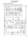
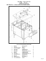
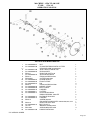
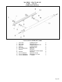
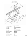
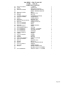
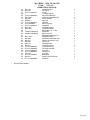
1
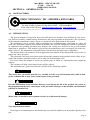
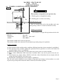
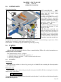
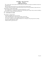
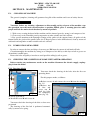
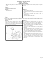
MACHINE : CIRCULAR SAW
TYPE:
STA 315
OPERATION MANUAL
ZMM “STOMANA” JSC - SILISTRA
STA 315
OPERATION MANUAL
ATTENTION: Before commissioning it is necessary to get acquainted with all the instructions of this manual. The manufacturer is not responsible for damages
caused due to improper operation of the machine or amendments in the design.
MACHINE : CIRCULAR SAW
TYPE:
STA 315
OPERATION MANUAL
TO OUR CUSTOMERS
This manual contains all the instructions required for the faultless operation of the machine and its respective maintenance, as well.
Thus, during the warranty period, you will receive for free all components that have
presented eventual defects.
The producer is always at your disposal for resolving of problems that machine operators may encounter during operation, and for delivery of spare parts, too.
Your recommendations related to this manual are valuable contribution to the improvement of the products offered by ZMM “Stomana” JSC to its customers.
Page 2
MACHINE : CIRCULAR SAW
TYPE:
STA 315
OPERATION MANUAL
СONTENTS
SECTION A: GENERAL DATA
A.1. MANUFACTURER
A.2. INTRODUCTION
A.3. CORRESPONDENCE
A.4. NAME PLATE
A.5. FIELD OF APPLICATION
A.6. WORKING CONDITIONS AND REQUIREMENTS
A.7. ТECHNICAL CHARACTERISTICS
A.8. NOISE CHARACTERISTICS
SECTION B: SAFETY OF WORK
B.1. SAFETY INSTRUCTIONS
B.2. DESIGN MEASURES FOR ENSURING SAFETY FOR WORK
SECTION C: ASSEMBLY OF MACHINE
C.1. REQUIREMENTS TO THE WORKING AREA
C.2. UNLOADING OF MACHINE
C.3. DESLUSHING OF MACHINE
C.4. FOUNDATIONS LAYOUT
C.5. ASSEMBLY OF THE DISASSEMBLED UNITS
C.6. CONNECTION TO THE MAINS
C.7. CONNECTION TO THE ASPIRATION DEVICE
SECTION D: FITTING AND OPERATING OF MACHINE
D.1. OPERATING OF MACHINE
D.2. CONTROL PANEL
D.3. STARTING
D.4. STOPPING
SECTION E: DESCRIPTION OF MACHINE
E.1. TECHNOLOGICAL PART
E.2. ELECTRICAL PART
SECTION F: MAINTENANCE
F.1. CLEANING OF MACHINE
F.2. LUBRICATION OF MACHINE
F.3. CHECKING THE CONDITION OF SOME UNITS AFTER OPERATION
F.4. TROUBLE-SHOOTING
SECTION G: APPENDICES
G.1. WIRING DIAGRAM AND LIST OF THE ELECTRICAL COMPONENTS
G.2. ELECTRIC CABINET – LAYOUT OF COMPONENTS
SECTION H:
CATALOGUE OF SPARE PARTS
Page 3
MACHINE : CIRCULAR SAW
TYPE:
STA 315
OPERATION MANUAL
SECTION A: GENERAL DATA
A.1. MANUFACTURER
ZMM “STOMANA” JSC , SILISTRA, BULGARIA
Tel.: 086 /821058; Commercial Dpt. 086 /821052, 16 Tutrakan Blvd.
FAX : 086 /821071 E-mail: [email protected] www.stomana.net
A.2. INTRODUCTION
The present manual is designed for those who will operate the machine. You will find in it the necessary data for assembly, commissioning, maintenance and safety operation of the machine. The experience
of the company manufacturer and its experts in considered in the preparation of this manual.
We recommend you to consider with responsibility our recommendations concerning the safety of
work. The operations requiring disassembly of machine and electrical components should be performed
by authorized and qualified personnel only. Repairs and settings not described in the present manual
should not be performed. This manual is prepared by the manufacturer and is an integral part of the machine's delivery. The information contained herein is intended for specialists and is compulsory.
The manual defines the machine's field of application and contains all the information necessary for its
proper and safety operation.
The permanent and exact observation of the instructions contained in this manual ensure safety of personnel and machine, profitable work as well as long life of the machine itself.
For better clarity this manual is divided in separate parts in which are contained the more important
subjects.
The contents will allow you to find fast the specific subjects.
The important text is printed in bold and is marked by the following symbols:
WARNING
This means that you should proceed very carefully in order to avoid situations that could be dangerous to human life or may cause serious injury to the personnel.
ATTENTION
Provides information about situations that may occur during the life of the product, the system or
the equipment and that may cause injury to the personnel, damages on the machine, environmental
pollution or financial loss.
CAUTION
Means that you should be more cautious in order to avoid material damage.
i
INFORMATION
Very important instructions.
Some figures and information in this manual may not coincide with those of the machine purchased by
you.
Page 4
MACHINE : CIRCULAR SAW
TYPE:
STA 315
OPERATION MANUAL
The producer is constantly working on the improvement and renovation of the product and may introduce modifications without prior notification.
At preparation of this manual are considered all the operations belonging to "normal servicing". Repair
works and other operations not mentioned in the manual should not be undertaken.
All operations requiring disassembly of machine parts should be carried out by technically qualified
personnel.
The instructions of this manual should be observed for correct usage of the machine.
Use only original spares of ZMM "Stomana" JSC.
The manufacturer should not be held responsible for damages caused by the use of spares which are
not original.
i
INFORMATION
The machine can be operated and serviced only by specially trained personnel, well acquainted
with this manual.
A.3. CORRESPONDENCE
In case of technical problem please contact the Seller or Service department.
In the correspondence or telephone call with them concerning the purchased machine please supply
the following information:
ª Machine serial number
ª Operating voltage and frequency
ª Date of production
ª Detailed description of the eventual failure
ª Detailed description of the working process
ª Total time of operation – working hours;
In case of enquiry concerning the electrical part is necessary to provide the data from the name plate.
A.4. NAME PLATE
A.5. FIELD OF APPLICATION
This machine is designed for longitudinal cutting, transversal cutting, and cutting of planes of wood or
other materials similar to wood (e.g. wooden-fiber plates, chipboards, plywood, laminated and nonlaminated planes etc.)
You may not process on this machine materials, other than those as indicated above, or materials other
than wood.
Page 5
MACHINE : CIRCULAR SAW
TYPE:
STA 315
OPERATION MANUAL
A.6. WORKING CONDITIONS AND REQUIREMENTS
fig. 1
ATTENTION
The machine is designed for one operator only.
А – Working place at longitudinal cutting
B
В – Working place at transversal cutting.
Tools that may be used:
A
May be installed and used on the machine tools complying with pr. ЕN847-1 related to manual feed only.
Working environment
The machine is designed for operation under the following environmental conditions:
Humidity
Max 90%
Temperature
Min +1°С Max +40°С
Altitude
Max 1000 м
The machine should not be open-air operated.
The machine should not be operated in environment presenting danger of explosions.
Defense to operate
ª The operation of the machine under conditions differing from those above mentioned is prohibited.
ª The operation of the machine without the protection devices provided, as well as the removal of
any part of those devices, is prohibited.
ª Materials differing from those described above may not be processed on the machine.
ª Pieces, whose dimensions differ from those described above, may not be processed on the machine.
ª Tools that do not comply with pr. ЕN847-1 and tools, whose dimensions do not comply with the
cutting disk shaft diameter, may not be used.
ª Introduction of modifications in the machine is prohibited.
The sole and exclusive liability in case of injury of personnel and damages of the machine as a result
of processing of unspecified materials shall be borne by the machine operator.
Page 6
MACHINE : CIRCULAR SAW
TYPE:
STA 315
OPERATION MANUAL
A.7. ТECHNICAL CHARACTERISTICS
Circular saw
Diameter of the circular disk
Max
min
Shaft diameter
Shaft r.p.m.
Length of rip fence
Maximal cutting length:
with extension board
Inclination of circular disk
Maximal cutting height at 90°:
Cutting disk with diameter ø 315
Cutting disk with diameter ø 250
Maximal cutting height at 45°:
Cutting disk with diameter ø 315
Cutting disk with diameter ø 250
Diameter of aspiration tip
Motor output
3- phase
1- phase
Dimensions of the operation board
Movable table
- Dimension of the table
- Max. length of cutting
- Length of support ruler
Mass of the machine, about
Required space :
STA 315
mm
mm
mm
min-1
mm
ø315
ø250
ø30
4000
800
mm
620
0° to 45°
mm
mm
102
72
mm
mm
mm
72
49
ø120
kW (HP)
kW (HP)
mm
3.0 (4.0)
2.2 (3.0)
800х970
mm
mm
mm
kg
m
600х500
620
1219
340
3.5 х 2.5
Upon special request
Unit with scoring circular disk
Diameter of undercutting disk
mm
Shaft diameter
mm
Shaft r.p.m.
min-1
Power
kW (HP)
Motor output 3- phase
kW (HP)
T- groove in the working table- 3/8” x ¾” (9.525x19.05 mm)
from left side of the blade
Cross cut fence. The support of the fence is made aluminum alloy
with length 460 mm. There is a possibility for fixing through 15º
with the help of pin. The fence mounted in T- groove in the working table
Eccentric clamp with fine adjustment by height , mounted in movable frame
Max cutting width with rip fence– including rip fence, extension
mm
table and 2 support legs
Max cutting width with rip fence– including rip fence, extension
mm
table and 2 support legs
Length of the profile of the rip fence
mm
Sucking pipe with hose, for max width of cut with rip fence
mm
Prolongation table
Length
mm
Width
mm
Mobility kit
ø120
ø20
8000
0.75 (1.1)
4.0 (5.5)
950
1270
1100
950, 1270
850
700
Page 7
MACHINE : CIRCULAR SAW
TYPE:
STA 315
OPERATION MANUAL
A.8. NOISE CHARACTERISTICS
ATTENTION
A continuous noise exposure over above 85 dВ (А) may result in health injury. That is why we
recommend using in such cases noise protection devices like ear-plugs, earphones, etc.
Statement on the emitted noise:
1. /А/ weighed level of noise pressure at idle
LpfA = 79 dB
Indefiniteness К = 2 dB
2. /А/ weighed level of noise power at material processing
- LwA = 108 dB
Indefiniteness - К = 2 dB
At 95% probability
Page 8
MACHINE : CIRCULAR SAW
TYPE:
STA 315
OPERATION MANUAL
SECTION B: SAFETY OF WORK
B.1. SAFETY INSTRUCTIONS
ATTENTION
Before commissioning, use, servicing, repair, cleaning or any other operations on the machine
read very carefully this manual.
The manufacturer shall not be liable for any damages on the machine or any injury of personnel
occurred as a result of failure to observe the operation, maintenance and safety instructions.
ª Only personnel trained and acquainted in detail with the operation of the machine and especially with
the dangers during operation of this kind of machines and being safe and controlling completely their
mind may operate the machine.
ª Do not operate the machine beyond the safety instructions and without the protection devices.
ª Follow strictly the Operation and service manual.
ª During all preparation activities, removal of failures, maintenance works and other, switch off the machine from the electric mains by pulling the supply coupling from the connector of the starter.
ª Before commissioning check the availability and the condition of all protection devices.
ª Do not operate the machine with gloves.
ª Clean thoroughly the machine from all dust and chips after work.
ª Do not clean the machine by water neither when switched on nor when switched off.
ª Always keep the working place of the machine in clean condition.
ª Remove from the machine and the operation surface all adjustment tools before operation.
ª Before any electrical connection, keep the machine switched off.
ª Before commissioning of the machine make sure that the connection to the electric mains is properly
effected.
ª Use the machine and the tools only for the purpose they are intended for.
ª Do not operate the machine in damp premises and do not leave it under the rain or at low temperatures
ª Never leave the machine operate without control when you are apart of it.
ª Do not work with loose clothing, free hair or long stoles.
ª Remove all bracelets, watches, chains and other similar objects.
ª The sleeves of the working clothing must be always buttoned.
ª In order to protect yourself from the noise, always work with headphones.
ª Always work with protection goggles, mask against the dust and with the other protection devices.
ª Keep children apart from the machine and take care to prevent machine’s operation by children.
ª Teenagers under the age of 16 may operate the machine under the supervision of skilled expert – adult
person only.
ª Provided the machine operates longer, it should be connected to the chip and dust aspiration device.
ª Before commissioning check the pieces for defects, e.g. free knots, fissures, nails, metal objects and
other foreign objects.
ª Use only perfectly sharpened tools.
ª Do not use cracked, damaged, wrong-shaped or incorrectly sharpened tools.
ª Keep always the tools with due care and do not allow unauthorized personnel to handle them.
ª Do not use the tools under speeds that exceed the maximal ones as specified by the respective tool
producer.
ª Do not use in any case tools of alloyed steel HSS.
ª Clean tools’ coupling surfaces and check for presence of swellings and dints.
ª Do not clean the tools by means of wire brush; do not use water in any case.
ª When handling the tools, use protection gloves whenever possible.
ª Do not open in any case the protection covers and doors while the machine is under operation.
ª Always operate the machine with protection devices, support rulers etc. in good order.
ª Do not pass your hands or other parts of your body to the mobile parts of the machine.
Page 9
ª
ª
ª
ª
ª
ª
ª
ª
ª
ª
ª
ª
ª
ª
ª
ª
MACHINE : CIRCULAR SAW
TYPE:
STA 315
OPERATION MANUAL
Process only materials the machine is designed for.
Ensure proper lighting (500 lux) that would not blind the eyes and avoid the stroboscopic effect.
The repair or maintenance works on the machine must not be carried out by unauthorized personnel.
The transportation, installation and assembly of the machine should be assigned to qualified personnel
only possessing the required knowledge and equipment for that purpose.
All interventions to the electrical equipment may be carried out solely and exclusively by qualified
personnel who possess the required knowledge for that purpose.
Do not modify in any case the electric equipment of the machine.
Make use of splitting cutter complying with the norms and corresponding to the respective circular
disk only.
Whenever the distance between the circular disk and the parallel support ruler is less that 120 mm,
make use of a pushing wooden bar
The chip and dust aspiration device must ensure a minimal rate of air delivery of 1800 m3/h at a speed
of 25-30 m/sec.
Provided the piece is fed by the feeding device, you must always use the splitting cutter in order to
prevent the back hit.
Do not switch on the machine when the covers of the electric board and the motors are opened.
You may make trial sections to check the adjustment of the tools when the protection devices are
mounted and are in good working condition only.
There must be sufficient space around the machine in order to ensure that the operator can always
stand outside the areas of potential danger.
Clean regularly machine’s board and the floor from dust and chips.
Whenever stopping the machine for adjustment, repair, maintenance, cleaning and other purposes, set
the main switch to position Zero, give warning to the other people by means of warning plate and lock
the main switch by padlock.
The key of the padlock must be kept by the authorized operator.
Training of the servicing personnel
All servicing personnel must be trained to operate and maintain the machine.
The training should include the following special features:
- General principles of machine’s driving, the proper operation, adjustment of support rulers, as well as
the use of appliances for special kinds of processing.
- The proper handling of the piece during processing.
- The position of the hands towards the cutting disks during processing and afterwards.
The servicing personnel must be informed about the dangers during machine’s operation, as well as
about the respective protection measures.
The servicing personnel must be trained to carry out periodical checks of the protection devices.
The servicing personnel must be informed about the use of the protection devices.
Additional dangers
Despite all operation and safety rules contained in this Operation and service manual, the following
additional dangers may occur:
- Contact with the tool;
- Contact with the rotating parts of the driving (pulleys, belts etc.)
- Back hit of the piece or parts thereof;
- Possible danger of dust when operating without aspiration device.
However, the safety depends mainly on you.
Bear in mind that you always undertake some risk when operating the machine.
Page 10
MACHINE : CIRCULAR SAW
TYPE:
STA 315
OPERATION MANUAL
B.2. DESIGN MEASURES FOR ENSURING SAFETY FOR WORK
The machine includes the following safety equipment and measures:
ª Forced splitting cutter
Prevents the back hit of the piece and be adjusted horizontally and vertically towards the circular disk.
ª Protections cover of the circular disk above the board.
The protection cover is fixed on the splitting cutter and prevents the contact with the part of the circular disk that is not used for cutting.
The cover may be removed from the splitting cutter without tools for closed sections.
The protection cover is made out of material that may be easily broken by the circular disk.
ª The whole circular unit may be lowered below the operation table; for that purpose it is required to
remove the protection cover from the splitting cutter.
ª Locking device of the circular disk position adjusted by height and inclination.
ª Tool tightening flanges connected by means of a key to the shaft for prevention of tool self-loosening
during machine’s stop.
ª Left-thread nut for tool tightening on the shaft.
ª Sockets of scorring circular adjustment switches.
ª Parallel support ruler.
Designed for support and precise guiding of the piece during longitudinal cutting; worked out of material that may be easily broken by the circular disk – aluminum.
Ruler’s guiding plane may extend from board’s front edge to the rear edge of the splitting cutter.
The parallel support ruler may be used with its high guiding plane (90 mm) and low guiding plane (12
mm), as well, when cutting narrow and thin pieces.
The parallel ruler may be adjusted towards the circular disk without tools, and its position may be read
on a scale.
ª Chip collector placed under machine’s board.
Used for collection and leading away of ships and dust released during operation.
ª Connection tip to the chip and dust aspiration device.
ª Plate “arrow”, showing the direction of circular disk rotation, fixed on the protection cover.
ª Movable table equipped with support ruler, made out of material that may be easily broken by the circular disk – aluminum.
The support ruler may be rotated around the vertical axis within 0o to –45o and to be locked in the adjusted position.
All adjustment works on the telescopic ruler and the tightening device may be performed without
tools.
ª Perfectly sharpened tools.
The blunt tools present a danger of back hit, overload the machine and lead to bad processing of the
surface.
ELECTROEQUIPMENT
ª Electronic brake for electrodynamics stops of the motor.
Ensures the stop of tool’s rotation for less than 10 seconds upon switching off of the motor.
ª Ensure proper protection of motor at machine’s overloading.
ª Minimal voltage protection.
Provided the voltage falls off, the machine stops operating; provided the voltage is restored, the machine remains motionless.
In order to start the operation again, it is required to act as for initial commissioning.
ª The body of the machine and the motors are nullified in order to prevent injury from the electric current.
ª The electric board and the motors are secured against dust penetration (IP54).
ª There is a protection lock provided in order to prevent the motion of the undercutting disk when the
main disk is not switched on.
ª There is a possibility to lock the main switch in order to prevent the accidental operation of the machine.
Page 11
ª
ª
ª
ª
MACHINE : CIRCULAR SAW
TYPE:
STA 315
OPERATION MANUAL
End switch that does not allow the operation of the machine during replacement of the tools.
Rest for the piece during the undercutting process.
Emergency stop.
Protecting the motors of overcharge.
Page 12
MACHINE : CIRCULAR SAW
TYPE:
STA 315
OPERATION MANUAL
SECTION C: ASSEMBLY OF MACHINE
C.1. REQUIREMENTS TO THE WORKING AREA
fig. 2
Choose suitable location for the machine, having in mind the shift of the
mobile board.
Follow the instructions as specified in
Section B.
The preliminary chosen positioning
location must ensure suitable connection
to the electric mains and to the chip and
dust aspiration device.
Ensure proper lighting (500 lux) that
would not blind the eyes and avoid the
stroboscopic effect.
Check the loading capacity of the
floor having in mind that the machine
must be simultaneously leveled on its
four support points.
Besides, it is necessary to ensure a
distance of at least 0.8 m around the machine.
You must ensure suitable space for
feeding and removal of long pieces at
machine’s inlet and outlet.
C.2. UNLOADING OF MACHINE
The hoisting and shifting of the machine must be carried out by suitable personnel especially
trained for that kind of work and disposing of the required equipment.
WARNING
During loading and unloading operations the machine must be handled with extreme precaution
and hits and pushes must be avoided in order to prevent injury of personnel and damage of the
goods.
During hoisting and shifting there must be not people near to the load hung or within the operation scope of the crane
The shifting of the machine and its parts must be carried out only by transportation means that correspond to the weight of the machine, e.g.
- Fork-lift truck;
- Wheelbarrow;
- Crane;
ATTENTION
For hoisting of the machine you will need a fork-lift truck with fork long at least 1200 mm.
Page 13
B
А
MACHINE : CIRCULAR SAW
TYPE:
STA 315
OPERATION MANUAL
- Ensure a fork-lift truck A with the required loading capacity corresponding
D
to machine’s weight.
- The fork B should be brought under
the machine in a way as presented in
fig. 3.
C
In case you dispose of crane or other
similar means, act as follows:
- prepare 2 ropes or belts C with the required loading capacity and length.
- The ropes should be hung on the hook
of crane D with loading capacity corresponding to that of machine’s weight.
- The ropes are hoisted by the crane and
are hung on the four hooks provided for
the hoisting of the machine.
WARNING
fig. 3
Check the secure fixing of the
hoisting hooks to machine’s body.
ª Adjust the ropes well and, if required, the crane should move slightly apart in order to ensure the
stable vertical hoisting without inclination of the machine.
ª The machine must be hoisted slowly and with extreme precaution in order to avoid pushes and
swinging of the load.
ª After the machine is hoisted at 1 m height, stop the hoisting and mount the four leveling supports to
machine’s body.
ª Place the machine on the chosen location by means of the crane.
ª Level the machine by means of the four leveling supports in order to effect a stable state.
C.3. DESLUSHING OF MACHINE
Remove the anti-corrosion grease from all unpainted machine parts using kerosene, turpentine or ordinary cleaning products commercially available.
Do not use nitro- thinners or similar diluents and by no means use water.
C.4. FOUNDATIONS LAYOUT
The stable construction of the machine, ensuring precise leveling and vibration-free operation does not
require any foundations.
Furthermore, an optional mobility device could be attached to the machine, allowing the machine to be
moved.
C.5.
ASSEMBLY OF THE DISASSEMBLED UNITS
With view to the transportation and packaging, some parts of the machine are delivered in unassembled condition.
You will find hereafter instructions concerning the assembly of those parts.
Page 14
MACHINE : CIRCULAR SAW
TYPE:
STA 315
OPERATION MANUAL
C.5.1. Assembly of extension support
One man is required to assemble the extension support.
- Release the screw A placed on the fixed board B of the
machine.
- Mount enlarging support D to motionless table B watch
the screw A get in the channel a support.
- Tighten slightly screws A.
- You can level (if applicable), by means of the leveling
screws C, the front edge of the extension support to the
fixed board.
- Tighten bolts A.
B
А
D
C
C.5.2. Assemble of movable table /fig. 5/
fig. 4
One man is required to assemble the movable table.
Unscrew bolt D together with a
washer and the buffer, being on guiding
B.
B
Release screw C.
Mount mobile table A to motionless
guiding B.
Put support F in an aperture on mo- А
bile table to observe that screw C to get
in the channel a support. Tighten screw
C.
C
Screw up lengthening E to guiding
B. Screw up bolt D together with a
F
washer and the buffer to lengthening.
fig. 5
C.5.3. Assembly of parallel ruler
E
D
H
One man is required to assemble the
parallel ruler.
- Unscrew nuts D (fig. 6) from studs
C and remove one of the washers E
placed on the studs.
J
I
ATTENTION
L
Do not alter the position of washers
A, which are adjusted by the producer.
Make sure that each of nuts A has
its washer E.
D
G
М
E
C
F
K
A
- Assemble the guiding girder F to the
fixed board G.
fig. 6
- Place again the removed washers E
and screw nuts D without tightening.
- Fit together the ruler I and the support J and assemble it to the girder F by tightening the handle M (see
the plate). Center the ruler I by means of right angle (V-shaped steel) towards the fixed table G, by slop
the girder F, and tighten those nuts D.
Page 15
MACHINE : CIRCULAR SAW
TYPE:
STA 315
OPERATION MANUAL
- Unscrew screws K from boards G.
- Assemble ruler L and tighten screws K without exercising pressure.
- Cut a sample piece, measure it and adjust the ruler L tighten screws K.
C.5.4. Assembly of circular disk protection cover.
I
E
- By means of the hand wheel A (fig. 7) raise the
circular disk B and the splitting cutter C over the operation board D.
- Unscrew nut E of the protection cover F.
- Assemble the protection cover F on the splitting
cutter C in a way to make the holes H and I in the
splitting cutter and the protection cover coincide.
- Place and tighten nut Е.
F
H
D
C
B
C.5.4. Assembly of the support ruler for transversal cutting
- Unscrew handle A (fig. 8).
- Mount support ruler C through pin D in centering
aperture E.
- Adjustmobile rod F so cotter B to get in channel G
on a basic frame.
A
fig. 7
- You can adjust, by means of scale
K, the ruler under some angle towards the circular disk.
- Upon adjustment of the ruler,
tighten again the handle A.
F
А
H
D
K
E
G
B
C
fig. 8
C.6. CONNECTION TO THE MAINS
ATTENTION
The connection of the machine to the electric mains, as well as all subsequent checks, must be
carried out by electrical technician only.
ª Check by suitable apparatus the good condition of the nullifying and earthling device.
ª Check whether the supply voltage and frequency of the current correspond to the data stated on machine’s plate.
The deviation of the supply voltage must not exceed
+ 5 %. (for instance: a machine operating under supply voltage of 400V can work within 370 to 420 V).
ª In order to define the required section of the supply cable, refer to the data of the amperage, stated on
machine’s plate, as well as to the table below:
Page 16
MACHINE : CIRCULAR SAW
TYPE:
STA 315
OPERATION MANUAL
Electric current (А)
Up to 10
from 10 to 14
from 14 to 18
from 18 to 22
from 22 to 28
from 28 to 36
From 36 to 46
Section of the cable
2.5 mm2
2
4.0 mm
6.0 mm2
6.0 mm2
10.0 mm2
10.0 mm2
16.0 mm2
Fuse
12А АМ
16А АМ
20А АМ
25А АМ
32А АМ
40А АМ
50А АМ
ª We do recommend to use a rubber insulated supply cable type H07RN (WDE0282) and to take the necessary
measures for its protection from mechanical damages.
ª Connect the supply cable to the respective terminals in
the incoming electric board (L1, L2, L3, N, and PЕ)
(fig. 9).
ª Provided there is CEE socket available (380V, 16A),
the connection to the mains is carried out by means of
respective CEE plug (L1, L2, L3, N, PЕ).
ATTENTION
During initial commissioning and after each modification of the connection to the three-phase mains, check
whether the direction of rotation of the shaft corresponds to that indicated on the plate. Provided the rotation is in the opposite direction, change the connection
points of the three-phase cables L1 and L2.
fig. 9
C.7. CONNECTION TO THE ASPIRATION DEVICE
A
B
The chip and dust aspiration device must ensure a
minimal rate of air delivery of 1800 m3/h at a speed of 25-30
m/sec.
ATTENTION
The dust and chips aspiration device must be switched on
simultaneously with the motor of the machine.
C
D
fig. 10
- Connect a hose with diameter ø60 mm to the aspiration
tip A of the protection cover B and tighten the hose by means
of a clamp.
- Connect a hose with diameter ø120 mm to the aspiration
tip C placed on side D of the machine. Tighten the hose by
means of a clamp.
Page 17
MACHINE : CIRCULAR SAW
TYPE:
STA 315
OPERATION MANUAL
SECTION D: FITTING AND OPERATING OF MACHINE
D.1. FITTING AND OPERATING OF MACHINE
D.1.1. Tool assembly and adjustment
Before any works on tool assembly and adjustment and on the splitting cutter, disconnect the machine
from the electric mains.
You can place on the shaft of the machine standard circular disks with diameter of the hole of ø 30 mm
and outside diameter within the range of ø250 to ø315 mm.
A
C
WARNING
D
Do not place in any case circular disks with diameter of the hole larger than ø 30 mm and
bushes.
Check the circular disk for fissures, distortions,
dints on the surface, damaged teeth, as well for the
maximal permissible rotations per minute.
Clean well the operation surface of the board and
remove all unnecessary objects.
B
H
J
G
I
L
fig. 11
L
M
fig. 12
- Release the protecting cover of circular disk А (fig.
11) looking the fig. 7.
- Release the insert C, to ensure access to the shaft of
the circular disk.
- By means of the hand wheel G, position the shaft of
the circular disk in the lower position and lock by the
lever H.
- By means of the hand wheel I, position the circular
unit in position of 90o towards the operation board D
and lock by the lever J.
Press wafers L (fig. 12) in the indicated direction in order to release the protection cover M and open
the cover to ensure access to the shaft of the
circular disk.
T
O
- Put the special wrench Т (fig. 13) in hole
over the shaft, and lock the spindle of circular saw.
- Unscrew the nut P by means of wrench O
(S=36 mm) (fig. 13)
ATTENTION
The thread of the nut is left-hand!
- Remove carefully the external pressing
Q
P
fig. 13
Page 18
MACHINE : CIRCULAR SAW
TYPE:
STA 315
OPERATION MANUAL
flange Q from the shaft.
- Clean thoroughly the surface of the shaft and the flanges.
- Check the surface of the shaft and the flanges for distortions, dints and sharp edges. The surface must be
perfectly processed.
Check the circular disk for fissures, damaged teeth, distortions, maximal r.p.m. and the compliance of
disk’s hole with the shaft.
WARNING
Do not use damaged tools or tools in poor condition.
The utilization of distance bushes to equalize the diameter of the disk and the diameter of the
shaft is prohibited.
Use only perfectly sharpened tools. Blunt tools present a danger of reverse hit of the piece or any
parts thereof.
Use protection gloves when handling the circular disks.
- Clean thouroughly the surface of the circular disk.
Min 3 ìì
- Assemble the circular disk on the shaft, having in
Màx 8 ìì
mind shaft’s direction of rotation.
- Assemble again the external pressing flange Q and
tighten well the nut P.
- Close the protection cover M.
D.1.2. Adjustment of splitting cutter
The splitting cutter must be adjusted so that the distance between it and the crown of the circular disk is 3-8
mm along the whole height of cutting; the upper point of
the cutter must not be below the base of the upper tooth of
fig. 14
the crown of the circular disk (fig. 14).
By means of spanner (S=6) release the screw B, you can alfig. 15
ready adjust the splitting cutter in horizontal and vertical direction in the plane of the circular disk (fig. 15).
The adjustment of the splitting cutter and the circular disk in
one and the same plane is made through screws C.
Afterwards screw thouroughly the screw B, paying attention
to not alter the adjusted position of the cutter (fig. 14). The
splitting cutter must not be thicker than the width of the section
obtained as a result of the cutting by the circular disk and must
not be thinner that the body of the circular disk.
С
В
i
INFORMATION
The machine is delivered along with splitting cutter 2.8 mm
thick.
D
B
D.1.3. Assembly and adjustment of the undercutting disk
Assembly of the undercutting disk
E
- Lock the shaft B (fig. 16) by means of internal hexahedral wrench
A (S=8) and unscrew the nut C (right-hand tread) by means of the
spanner D (S=36).
- Remove the pressing flange E.
fig. 16
A
C
Page 19
MACHINE : CIRCULAR SAW
TYPE:
STA 315
OPERATION MANUAL
- Clean thouroughly the surface of the shaft and the flanges.
- Assemble the circular disk, having in mind the direction of rotation.
i
INFORMATION
The undercutting disk rotates in a direction opposite to that of the main circular disk.
- Assemble again the pressing flange E and tighten the nut C.
Adjustment of the scorring circular disk towards the main circular disk
The scorring circular disk must be adjusted in height in a way to effect a section 1,5-2 mm deep.
The adjustment of the scorring circular disk by height is performed in the following way:
C
A
B
G
fig. 17
E
- Position the circular unit in position of 90o towards the operation board and lock it in that position (fig. 17) .
- Place the spanner A in the end of the lifting
screw B, in order to adjust the scorring circular
disk G to the required height above the operation
table C.
- The adjustment range by height is within 0 to 5
mm.
- You can adjust the scorring circular disk in the
plane of cutting of the main circular disk, as follows:
- Place spanner A in hole E of the operation board
C.
- Turn the spanner A to adjust the scorring circular disk in the plane of the main disk. The undercutting
disk shifts by 0.05 mm at each rotation of the spanner A.
The adjustment range is + 1 mm.
Upon completion of the adjustment, tighten again the screw by means of the spanner A.
Make a trial section and check the correct adjustment of the scorring circular disk towards the main
disk, and if required, keep on adjusting.
Operation of the scorring circular disk
The scorring circular disk is used to
prevent the damage of the edges during
cutting of plates covered by veneer or
other decorative materials.
The scorring circular disks may by
used in the following cases (fig. 18):
А – the thickness of the scorring circular disk equals that of the main circular disk.
В – doubled scorring circular disk:
by placing distance pads between both
parts of the disk you may achieve equal
or larger thickness compared to the
fig. 18
main circular disk;
С – cone scorring circular disk to level with the thickness of the main circular disk when disks of different thickness are used.
Page 20
MACHINE : CIRCULAR SAW
TYPE:
STA 315
OPERATION MANUAL
During cutting, in order to prevent the damage of one edge of the piece only, you may use every kind
of scorring circular disk.
In that case the main disk should be leveled with one side of the scorring circular disk only.
D.1.5. Operation of the circular saw
The circular saw can perform the following operations:
- Longitudinal cutting of pieces of massive wood;
- Transversal cutting of pieces of
massive wood;
- Cutting of planes.
Longitudinal cutting of pieces of massive wood
In order to carry out this operation
you must use the following safety devices:
- parallel ruler A;
- protection cover В of the circular
disk G;
- splitting cutter С;
- insert Е in the board;
The adjustment of the parallel ruler A
towards the cutting disk is measured by
the scale F.
А
C
B
E
F
G
I
K
fig. 19
Transversal cutting of pieces of massive wood
In order to carry out this operation you must use the following safety devices:
- mobile frame J;
- transversal support ruler I with support for the piece;
- protection cover В of the circular disk G;
- splitting cutter С;
- miter gauge К;
- insert Е in the board;
Cutting of planes
In order to carry out this operation you must use the following safety devices:
- mobile frame J;
- transversal support ruler I with support for the piece;
- protection cover В of the circular disk G;
- splitting cutter С;
- miter gauge К;
- insert Е in the board;
i
fig. 20
INFORMATION
For cutting of laminated plates it is required to make use of the scorring circular disk in order to
avoid the damage on the edges during cutting with the main disk.
The undercutting disk must be adjusted in height so that the depth of section is 1-1.5 mm (fig. 20).
Page 21
MACHINE : CIRCULAR SAW
TYPE:
STA 315
OPERATION MANUAL
Instructions on the use of the circular saw
- Adjust the protection cover of the circular disk as shown
on fig. 21.
- Feed the piece evenly, without pushing or taking it back
until the final cut.
- Adjust the circular disk at a height so that the tooth crown
is reliably covered by the protection cover (distance between
the protection cover and the piece – max 5 mm, fig. 24).
- Adjust the circular disk by height and inclination if the fig. 21
machine is not operated only.
- Use only well sharpened tools.
- Use the pushing wooden bar at the end of the cutting and when the distance
between the circular disk and the parallel support ruler is less than 120 mm;
- Make sure that the machine operates without vibrations.
- You must not place cracked or distorted circular disks. They must be immediately rejected and replaced by new ones.
fig. 22
- During repair and maintenance of circular disks with welded plates (e.g.
welding of new cutting plates), the structure of the disks (shape of teeth, width of teeth) must not be altered. For composite circular disks (i.e. disks with welded
plates) the new sharpening may be carried out up to the minimal dimensions of
the plate – 1 mm (fig.
22).
After that the
circular disk must be
rejected.
- choose the number
fig. 23
of teeth of the circufig. 24
lar disk so that at least 2-3 teeth operate simultaneously (fig.
23).
- If only one tooth (fig. 24) is in operation, you will achieve bad processing surface, the danger of reverse
hit increases, as well as the vibrations and the noise load.
Use of the support ruler for parallel cutting
фиг. 25
You can use the support ruler for parallel
cutting of widths of min. 2 mm.
The adjustment of the support ruler by
width is effected, as follows (fig. 25):
B
A
E
D
C
Place the handle D in middle (neutral) position and shift the support ruler to the required dimensions, reading the data directly
from scale E. For fine adjustment turn the
handle D in right direction until complete
tightening and turn the handle C. Upon
achievement of the required dimensions turn
the handle D in left direction until complete
tightening.
Page 22
MACHINE : CIRCULAR SAW
TYPE:
STA 315
OPERATION MANUAL
The aluminum support ruler A may be shifted by length and locked by means of handle B (fig. 25 and
26).
B
There are two possible positions of the ruler:
1). Horizontal position (fig. 26) – for cutting of thin
pieces with 15 mm minimal width.
А
WARNING
Use the pushing bar whenever the width is less than
120 mm.
If the width of the piece is less than 15 mm, the ruler
fig. 26
can enter into contact with the cutting disk.
Adjust the ruler for cutting width less than 120 mm when the machine is out of operation only.
2). Vertical position (fig. 25) – for other cases of longitudinal sections.
The parallel ruler should be pulled back in order to avoid the blocking of
the piece.
As a practical rule we may suggest the following:
The back side of the parallel ruler touches an imaginary line beginning
from the middle of the cutting disk and continuing backwards under 45o
(fig. 27).
For transversal cutting in order to produce short details the parallel
ruler should be pulled back so that its back side is placed ahead of the
teeth crown of the circular disk.
fig. 27
Inclination sections
A
C
- Release the handle A (fig. 28), in order to
rotate the support ruler С to the required
angle according to scale D.
- Screw again the handle А and, after adjustment the support ruler in desire angle,
tighten handle full.
D
fig. 28
Page 23
MACHINE : CIRCULAR SAW
TYPE:
STA 315
OPERATION MANUAL
D.2. CONTROL PANEL
Operation functions
F
D
E
H A
G
B
C
A-СЕЕ-socket/3Р+N+E;
400V;
16A/- for connection to and disconnection from the electric mains
through CEE plug.
B- main circuit-breaker – for
switching on and off of machine’s
electric supply. There is a possibility to lock it in position “0” in order
to avoid accidental commissioning.
Operated by turning. Position “1” –
ON. Position “0” – OFF.
C- Switch – works for turning on of
the scoring unit. Position ”1” ON.
Position ”0” OFF.
D, H - Emergency stop knob – for
normal or emergency stop. Acts by
pressing, during which the knob is
self-detained in pressed position.
Released by turning at right or pulling. When the knob is not released,
the machine cannot be switched on.
fig. 29
E - Green knob – to start the machine. Operated by pressing.
F - Breaker of disk’s protection cover – for locking of machine’s commissioning at open cover. If the
machine is in operation, it stops upon opening of the cover.
G- Red knob – to normally stop the machine. Operated by pressing.
D.3. STARTING
ATTENTION
Always check the protection devices before commissioning. Follow the safety instructions according to the service manual.
The commissioning is made, as follows:
1. Switch the main circuit-breaker B to position “1”.
2. Switch С rotating in position ”1” if We desired work with scorer.
3. Press the green knob G.
D.4. STOPPING
Normal stop
The stop of the machine is effected by pressing the red knob E, thus actuating the electrodynamics
brake of the motors.
Emergency stop
The emergency stop is effected by pressing the emergency knob D or H, thus actuating the electrodynamics brake of the motors.
ATTENTION
You must not stop the machine from the main circuit-breaker B, as in this case the electrodynamics
break will not operate.
Page 24
MACHINE : CIRCULAR SAW
TYPE:
STA 315
OPERATION MANUAL
SECTION E: DESCRIPTION OF MACHINE
E.1. TECHNOLOGICAL PART
8
7
9
11
10
5
12
6
14
13
15
4
2
3
1
fig. 30
Main components
1. Body
2. Inclination adjustment mechanism of the cutting disk
3. Control devices
4. Height adjustment mechanism of the cutting
disk
5. Adjustment mechanism of the scoring disk *
6. Parallel support ruler
7. Extension support
8. Fixed operation board
9. Protection cover with aspiration tip
10. Scoring disk
11. Cutter
12. Main circular disk
13. Support ruler
14. Movable board
15. Telescopic bar
*
*
*1) - Upon special request
The machine is designed for:
ª Longitudinal cutting of wood and other materials similar to wood (e.g. wooden-fibre planes, chipboards, plywood, laminated and non-laminated surfaces etc.) by means of the parallel support ruler
and pushing bar.
ª Cutting out of planes.
The machine is made of steel sheet iron and steel profile corpus on which stable working table is assembled. The table is castled from gray cast iron and its working surface is smoothed.
Page 25
MACHINE : CIRCULAR SAW
TYPE:
STA 315
OPERATION MANUAL
The circular disk is placed inside the board and my be adjusted by height and inclination towards the
operation board.
The tool support along with the gear are placed below the operation board.
Generally, the processed piece is placed on the board and is fеed to the preliminary adjusted for the respective process circular disk by hand.
For feeding purposes you may make use of the feeding device, as well.
The machine may be additionally completed by undercutting disk designed for prevention of barking
edges during the cutting operation of the main disk.
E.2. ELECTRICAL PART
The machine is equipped with:
- Thermal protection of the electrical motor
- Starter with CEE plug for connecting the machine to the mains
- The starter and motor are secured against penetration of dust /IP54/
- The starter is equipped with breaking unit which acts as emergency strop and provides its locking
- Protection against minimum voltage
- Breaker of disk’s protection cover.
Page 26
MACHINE : CIRCULAR SAW
TYPE:
STA 315
OPERATION MANUAL
SECTION F: MAINTENANCE
F.1.
CLEANING OF MACHINE
The general (complete) cleaning will guarantee long life of the machine and is one of safety factors.
WARNING
You must, before any cleaning, adjustment or disassembly activity of parts of the machine, stop
the operation, turn the main circuit-breaker to position ZERO, place a warning plate for other
people and lock the main circuit-breaker by means of padlock.
1. Wash every evening the board of the machine and the internal space by strong jet of compressed air.
2. Clean every week all mobile parts by turpentine or other suitable and safe solvents.
3. Pay special attention to the thorough cleaning of the guides of the support frame, all guides of the
format board, the girder of the parallel ruler, the T-shaped grooves in the format board; clean by means of
soft brush and turpentine or other suitable and safe solvents.
F.2. LUBRICATION OF MACHINE
In order to remove the dust and chips, clean once per 500 hours by means of soft brush all belts.
Clean thouroughly the machine by strong jet of compressed air and lay a thin layer of oil or grease on
all machine’s mobile parts.
Protect the belts and pulleys in order to avoid possible soiling by oil or grease.
F.3. CHECKING THE CONDITION OF SOME UNITS AFTER OPERATION
Before starting any maintenance works on the machine disconnect the electric supply, unplugging it from the mains.
F.3.1. Drawing of belts
You must check the drawing of the belts after the first ten
operating hours.
A
For this purpose make, as follows:
B
fig. 31
ª Release screws A and remove the cover B from the machine
(fig. 31/
ª Release nut
C first and
C
screw nut D
until the belts
are completely
bent (fig. 32);
D
ª Screw again nut C;
ª Install the cover B and screws A.
You must check the drawing of the belts at least once
per month.
The drawing of the flat belt is performed automatically, by means of a spring.
fig. 32
Page 27
MACHINE : CIRCULAR SAW
TYPE:
STA 315
OPERATION MANUAL
F.3.2. Check of the stop time of the circular disk
The machine is equipped with electronic brake for electrodynamics stop of the motor.
The time for complete stop of circular disk’s rotation should not exceed 10 seconds from the moment
of motor’s switching off.
The stop time must be checked once per month.
Provided the stop time exceeds 10 seconds, the brake must be checked by electrical technician.
The brake must not be operated more than 10 times per hour.
F.3.3. Check of safety devices
The safe operation of the machine depends on the safety devices as described in Section B2.
- Check every week the operation of the emergency stop, as follows:
- During normal operation conditions press the knob “Emergency stop”. The motor should stop.
- Check every week the operation of the micro switch for replacement of the tool, as follows:
A
B
Release the protecting cover А of circular disk B
(fig. 33) looking the fig. 7. Release the insert, to
ensure access to the protection cover of the circular.
Open the protection cover F (fig. 33).
Press the green knob.
The motor should not operate.
Check of the protection cover of the circular disk
F
Before operation, check the protection cover for:
- fissures;
- distortions;
- secure fixing on the splitting cutter;
You must not use cracked or distorted covers,
nor covers that can not be fixed in a secure way.
Check of splitting cutter
Before operation check the splitting cutter for:
- fissures;
- distortions;
fig. 33
- secure fixing on the support;
- the distance between the splitting cutter and the teeth crown of the circular disk must be 3 to 8 mm
along the whole cutting length;
- compliance with the thickness of the cutting circular disk.
You must not use cracked or distorted splitting cutters, nor cutters that do not comply with the thickness of the cutting disk.
E
GENERAL PROVISIONS
Check regularly for availability of warning plates on the machine and their good condition.
The plates must be available and legible.
It concerns especially the plate “Safety instructions”.
Removal from operation, storage – disassembly (rejection) of the machine
Switch off all electrical equipment during removal of the machine.
Page 28
MACHINE : CIRCULAR SAW
TYPE:
STA 315
OPERATION MANUAL
Provided the machine would not be use for some time, after switching off of all electrical equipment,
clean it thouroughly and process the operation board, the shaft of the circular disk and the other unpainted
parts by roof-protection product.
You should not store the machine in damp places and must protect it from environmental effects.
The machine is produced by non-toxic and safe materials. Upon rejection divide the metal and plastic
parts and smash them afterwards.
Emergency situations /states/
Switch off the electric supply immediately in case of flood of the operation area.
Before re-operation of the machine, it must be checked by trained authorized technician.
Switch off the electric supply in case of fire and use fire extinguishers.
Direct the jet to the base of the flame.
Before re-operation of the machine, it must be checked by trained authorized technician.
The operation area around the machine (please refer to Section C.1.) must always be unoccupied.
You must not operate the machine in environment presenting danger of explosion.
F.4.
TROUBLE-SHOOTING
WARNING
Before starting any repair works switch off the electric supply of the machine.
The machine has been tested in the production plant and you can freely operate it.
The incorrect and out of function use of the machine may result in damages.
Fault:
The machine does not start
Reason:
-The emergency stop knob is ON.
Repair:
Switch off the emergency stop by pulling and turning
at the right.
-The protection cover of the circular disk is Close the cover.
opened, thus actuating the protection cut-out.
-The cut-out of the operation loop is discon- Replace the cut-out. Remove the reason for cut-out’s
nected
failure.
-The automatic cut-out is switched off.
Restore the automatic cut-out.
Remove the reason for cut-out’s failure.
-Lack of electric current of one or more phases Check whether all 3 phases are under voltage
Failure:
The machine stops during operation
Reason:
-Lack of electric current of one or more phases
-The cut-out of the operation loop is disconnected
-Overcharge compared to the output of the
machine. The thermal switch of the motor is
disconnected.
- Failure of the motor
Removal:
Check whether all 3 phases are under tension
Replace the cutout. Remove the reason for cutout’s
failure.
Wait until the motor cools down.
Do not overcharge the machine.
Replace the motor.
Failure:
The motor operates, but the circular disk stops when in contact with the piece
Reason:
- The bents are loose
Removal:
Draw the belts
Page 29
MACHINE : CIRCULAR SAW
TYPE:
STA 315
OPERATION MANUAL
- The belts and pulleys are soiled with grease Clean thoroughly the belts and the pulleys or replace
or oil
the belts.
Failure:
Vibrations during operation
Reason:
- unbalanced tool
Removal:
- Sharpen properly the tool.
- Tighten the levers for height and inclination spindle
fixing.
- Level well the machine by means of all 4adjustment legs.
- Check the balance of the tool.
Fault:
There is no enough movement for adjusting of the scoring unit toward the cutting surface of the
main circular saw
Reason:
Removal:
There are different scoring discs– single and After rotating of the handle position 1 in one direcdouble. There is possibility your disc to be dif- tion you reach the end, but that is not enough to adferent than the disc with the help of which was just the scoring unit, you have to do the following:
made the machine adjustment.
1. Rotate the handle position 1 in opposite directionaround 10-12 revolutions.
2. Unscrew the nut М8 position 3 and bolt М8х25
position 4.
3. With light knocking on the axis, position 2 in the
both directions adjust the scoring disc maximum
close to the cutting surface of the main circular.
4. Screw the bolt М8х25 position 4 and nut М8 position 3.
5. Through rotating of the handle, position 1 in one or
other direction you can adjust finely the scoring
unit to the direction of the main circular. For one
revolution of the handle, the scoring moves with
0,05 mm.
Page 30
MACHINE : CIRCULAR SAW
TYPE:
STA 315
OPERATION MANUAL
SECTION G: APPENDICES
G.1. WIRING DIAGRAM AND LIST OF THE ELECTRICAL COMPONENTS
Page 31
MACHINE : CIRCULAR SAW
TYPE:
STA 315
OPERATION MANUAL
G.2. ELECTRIC CABINET – LAYOUT OF COMPONENTS
Page 32
MACHINE : CIRCULAR SAW
TYPE:
STA 315
OPERATION MANUAL
SECTION H: CATALOGUE OF SPARE PARTS
STA 315.01.00.00.00 BODY WITH PANEL
1
2
3
4
5
6
7
8
9
10
11
12
13
14
15
DIN 933
DIN 934
TS315.01.00.00.00
S315.73.01.00.01
ISO 7380
DIN 125A
DIN 7980
DIN 912
DIN 912
DIN 7980
S315.04.00.00.08
DIN 134
DIN 985
КЗМ 01.00.00.17
TS315.02.00.00.01
BOLT М16Х40
NUT М16
BODY
COVER
SCREW М 6Х10
WASHER M6
SPRING WASHER 2-6Н
SCREW М 6Х16
SCREW М12Х40
SPRING WASHER 2-12Н
STUD М12Х88
WASHER M12
NUT М 12
HOLLOW BOLT
PANEL
4
4
1
1
6
5
5
5
6
6
2
4
4
6
1
Page 33
MACHINE : CIRCULAR SAW
TYPE:
STA 315
OPERATION MANUAL
16
17
18
19
20
21
22
23
24
25
DIN 7967
DIN 913
ISO 7380
TS315.02.02.00.01
DIN 912
DIN 1481
DIN 7980
DIN 1481
DIN 912
TS315.17.00.00.00
NUT M6
FIXING SCREW М 8Х16
SCREW М6Х16
INSERT
SCREW М8х45
SPRING PIN Ф 6Х45
SPRING WASHER 2-8Н
SPRING PIN Ф 6Х30
SCREW М8х25
FRONT COVER
4
10
4
1
2
2
4
2
2
1
Page 34
MACHINE : CIRCULAR SAW
TYPE:
STA 315
OPERATION MANUAL
S315.08.00.00.00 MAIN CIRCULAR
1
2
3*
4
5
6
7
8
9
10
11
12
13
14
15
16
17
18
19
20
21
22
23
24
25
26
27
28
S315.08.00.00.01
S315.08.00.02.00
S315.08.00.27.00
S315.08.00.00.05
DIN 471
S315.08.00.00.24
DIN 913
DIN 6885A
S315.09.00.00.03
S315.09.00.00.04
S315.09.00.00.07
DIN 913
S315.09.00.00.08
S315.09.00.00.09
S315.09.00.00.10
S315.09.00.00.11
S315.09.00.00.12
S315.08.00.00.15
S315.08.00.00.16
DIN 912
DIN 472
S315.09.00.00.19
UN 732
DIN 7980
S315.09.00.27.00
NUT
FLANGE EXTERIOR WITH COTTER
CIRCULAR SAW ø315Хø30Х3
SHAFT WITH FLANGE ø30
RIVING KNIFE
RING FOR SHIFT Ф70
SUPPORTING RING
FIXING SCREW М 8Х8
COTTER А8Х7Х20
SCREW М10Х53
FRONT STRAP
PIN
FIXING SCREW М 6X20
MIDDLE STRAP
BACK STRAP
CARRIER
COTTER
SUPPORTING RING
RADIAL BEARING 6205-ZZ
DISTANCE BUSHING
CARRIER
SCREW М 8Х22
EQUALIZATION WASHER Ф42Х51Х0,5Х3,4 К2
RING FOR HOLE Ф52
BELT PULLEY
WASHER Ф 8ХФ35Х2,5
SPRING WASHER 2-8Н
HANDLE WITH BALL
1
1
1
1
1
1
1
2
1
1
1
2
3
1
1
1
1
1
2
1
1
4
1
2
1
1
4
1
* BY SPECIAL ORDER
Page 35
MACHINE : CIRCULAR SAW
TYPE:
STA 315
OPERATION MANUAL
S315.05.00.00.00 CARRIER FOR CIRCULAR
1
2
3
4
5
6
7
8
9
10
11
12
13
14
15
16
17
18
19
20
21
22
23
24
25
26
27
28
29
30
31
32
33
S315.05.00.00.01
S315.05.00.00.02
DIN 7980
DIN 912
S315.05.00.00.05
S315.05.00.00.06
DIN 7337 A
S315.05.00.00.08
S315.05.00.09.00
DIN 985
DIN 125A
DIN 7991
DIN 7991
S315.05.00.00.14
S315.05.00.00.15
S315.05.00.00.16
DIN 934
DIN 933
S315.05.00.00.19
DIN 934
S315.05.00.00.21
DIN 7991
S315.05.00.00.23
ST 01-02.00.00.02
S315.05.00.00.25
S315.05.00.00.26
S315.05.00.00.27
S315.05.00.00.28
DIN 7349
DIN 985
S315.05.00.00.31
S315.05.00.00.32
S315.05.00.00.33
BEAM
SPRING
SPRING WASHER 2-4Н
SCREW М 4Х10
SECTOR RIGHT
SEALING
BLIND RIVET Ø4Х20
STABILIZE STRAP
VALVE
NUT М 8
WASHER M8
SCREW М 8Х25
SCREW М 8Х16
STOP
PANTOGRAPH STRAP
SEALING
NUT М8
BOLT М8X30
FIXING SCREW
NUT М10
SECTOR LEFT
SCREW М10Х25
WASHER Ø10,5ХØ25Х8
CRADLE
SUPPORT BLOCK
BLOCK
WASHER Ø40ХØ24Х4
COLUMN
WASHER М16
NUT М16
BOLT SPECIAL
BLOCK
PLATE FOR TILTING
1
2
4
4
1
1
8
1
1
1
1
1
1
1
1
1
1
1
1
4
1
1
1
1
1
1
1
1
1
1
1
1
1
Page 36
MACHINE : CIRCULAR SAW
TYPE:
STA 315
OPERATION MANUAL
34
35
36
37
38
39
40
41
42
DIN 7980
DIN 912
S315.05.00.00.36
DIN 933
DIN 912
DIN 7980
S315.05.00.00.40
S315.05.00.00.41
S315.05.00.42.00
SPRING WASHER 2-10Н
SCREW М10Х50
NUT
BOLT М10X40
SCREW М 8Х25
SPRING WASHER 2-8Н
SUPPORT PLATE
BUSHING
ASPIRATION HOSE
2
2
1
1
3
3
1
3
1
K5-32.03.03.00.00 CARRIER FOR MAIN MOTOR
1
3
6
7
4
2
5
8
K5-3203.03.01.00
K5-32.03.03.00.03
SPZ630MN
DIN 931
DIN 125 A
DIN 7980
DIN 913
CRADLE, Т100
MOTOR
BELT PULLEY
BELT L=630
BOLT М10Х30
WASHER АМ 10
SPRING WASHER 2-10Н
FIXING SCREW М 8Х8
1
1
1
2
4
4
4
1
Page 37
MACHINE : CIRCULAR SAW
TYPE:
STA 315
OPERATION MANUAL
S315.06.00.00.00 DEVICE FOR LIFTING
1
2
3
4
5
6
7
8
9
10
11
12
13
14
15
16
17
18
19
20
S315.06.00.01.00
DIN 7980
DIN 912
PAP
DIN988
DIN 913
S315.06.00.07.00
S315.06.00.00.08
S315.06.00.00.09
S315.06.00.00.10
A586-65-М8-30
GN698-KU-24-M10
DIN 912
S315.06.00.00.16
S315.06.00.00.17
DIN 1481
UL808.1-20-12-62E
S315.06.00.00.20
GUIDE FOR LIFTING
SPRING WASHER 2-8Н
SCREW М 8Х25
BUSHING 2020 P10
WASHER Ф20ХФ28Х1
FIXING SCREW М 8Х8
INDEX
SHAFT FOR LIFTING
PIN
FLYWHEEL Ø160
HANDLE М8Х30
HANDLE
AXIS FOR BEARING 1528
AXIAL BEARING 1528
SCREW М8х35
BASE
WASHER
SPRING PIN Ф 5Х20
HINGED CLUTCH
SCREW FOR LIFTING
1
4
2
1
1
2
1
1
1
1
1
1
3
1
2
1
1
2
1
1
Page 38
MACHINE : CIRCULAR SAW
TYPE:
STA 315
OPERATION MANUAL
ТS315.32.00.00.00 DEVICE FOR TILTING
1
2
3
4
5
6
7
8
9
10
11
12
13
14
15
16
17
18
19
20
21
22
23
24
25
26
27
28
S315.07.00.00.02
S315.07.00.00.01
S315.07.00.00.26
S315.07.00.00.24
UL808.1-20-12-62E
S315.07.00.00.12
DIN 471
DIN 1481
DIN 125A
DIN 7980
DIN 912
GN598.5-KU-28
DIN 7991
AS2035
S315.07.00.00.15
DIN 912
DIN 7980
T17634
T17646
DIN 985
UL808.1-20-12-62E
S315.06.00.00.17
S315.06.00.00.09
TS315.32.00.00.14
BOTECO A583-65-M8-20
UN 732
DIN 439
STUD
NUT
SUPPORT FOR TILTING
SCREW FOR TILTING
HINGED CLUTCH
GUIDE FOR TILTING
AXIAL BEARING 8104
RING FOR SHIFT Ф20
SPRING PINФ 5Х20
WASHER M8
SPRING WASHER 2-8Н
SCREW М8х20
HANDLE
SCREW М 6Х10
AXIAL WASHER
FLYWHEEL SMALL
SCREW М10Х70
SPRING WASHER 10Н
FORK G 8X16 - M8
AXIS WITH SPRING LOCK G 8X16
NUT М 8
HINGED CLUTCH
WASHER
PIN
SHAFT FOR TILTING
HANDLE М8Х20
WASHER ф8хф30х2
NUT М 8
1
1
1
1
1
1
1
1
2
2
2
2
1
1
2
1
2
2
1
1
2
1
1
1
1
1
1
1
Page 39
MACHINE : CIRCULAR SAW
TYPE:
STA 315
OPERATION MANUAL
K5-32.20.00.00.00 PARALLEL RULER
1
2
3
4
5
6
7
8
9
10
11
12
13
14
15
16
17
18
19
20
21
22
23
24
25
26
DIN 912
S315.18.00.00.06
K5-32.20.00.00.03
DIN 934
K5-32.20.00.00.05
К5-32.20.00.00.10
ELC.100 A-12-C3
N740-40 M8
К5-32.04.00.00.19
К5-32.04.00.00.16
DIN 7980
DIN 933
MFN2300-00.04.00.02
DIN 125A
S2300.16.00.00.03
S315.18.00.00.07
DIN 934
DIN 913
DIN 985
DIN 125A
S315.18.00.00.20
К5-32.04.00.00.13
S315.18.00.00.18
GN5330-100-М12-E
DIN 439
SCREW М 5Х10
ECCENTRIC
STUD
NUT М10
PLATE
PORTER
HANDLE
HANDLE М8
STUD
PLATE
SPRING WASHER 2-6Н
BOLT М6Х12
COTTER
WASHER M12
PROFILE L=800 Т4570
ROLL
ECCENTRIC AXIS
NUT М8
FIXING SCREW М6Х8
NUT М 8
WASHER АМ 8
NUT М12-М6
TAG
STUD М12-М18x84
HANDLE
NUT М12
1
1
2
4
1
1
1
1
1
1
2
2
2
2
1
1
1
1
1
2
2
1
1
1
1
1
Page 40
MACHINE : CIRCULAR SAW
TYPE:
STA 315
OPERATION MANUAL
TS315.16.00.00.00 BEAM, CUT 630ММ
1
2
3
4
5
6
7
8
9
10
11
12
ISO 7380
DIN 125A
DIN 7980
DIN 912
DIN125A
К5-32.04.00.00.40
DIN 934
DIN 985
S315.18.00.00.31
TS315.16.00.00.01
TS315.16.00.00.02
SCREW М 5X10
WASHER M16
SPRING WASHER 2-8Н
SCREW М8Х20
WASHER АМ5
WASHER
NUT М16
RULER LEFT-RIGHT 0-600
NUT М16
SUPPORT STUD
BEAM Ф45, CUT 620
L –SHAPE
3
4
2
2
3
2
2
1
2
2
1
1
Page 41
MACHINE : CIRCULAR SAW
TYPE:
STA 315
OPERATION MANUAL
TS315.21.00.00.00 MOBILE FRAME SMALL
1
2
3
4
5
6
7
8
9
10
11
12
13
14
15
16
17
18
TS315.21.01.00.12
TS315.21.01.00.04
UN 792
ISO 7380
DIN 985
DIN 134
TS315.21.01.07.01
UN 792
ISO 7380
ERX 603-63-М8-50
DIN 985
DIN 125A
DIN 913
DIN 934
DIN 7980
TS315.21.01.01.00
ISO 7380
BRUSH
COVER LEFT
WASHER М6 (Ф6.4XФ10.0X0.7)
SCREW М 6Х10
NUT М 8
WASHER M 8
RADIAL-BEARING 3202-2RS
ECCENTRIC AXIS
WASHER М8 ( Ф8.4XФ13.0X0.8)
SCREW М8Х10
HANDLE М8Х50
NUT М 6
WASHER M6
FIXING SCREW М 8Х25
NUT М8
SPRING WASHER 2-6Н
FRAME
SCREW М6Х16
4
1
4
5
1
1
1
1
4
4
1
2
2
1
1
1
1
2
Page 42
MACHINE : CIRCULAR SAW
TYPE:
STA 315
OPERATION MANUAL
19
20
21
22
23
24
25
26
27
28
29
30
31
32
33
34
35
36
37
38
39
40
41
42
43
44
45
46
47
48
49
50
51
52
53
54
55
TS315.21.01.00.17
T1376
DIN 472
TS315.21.01.08.02
TS315.21.01.08.01
DIN 134
DIN 985
S2300M.11.00.03.03
TS315.21.01.00.05
DIN912
DIN 125A
BOTECO A583-65-M8-20
DIN 1481
TS315.21.02.00.08
TS315.21.02.00.04
DIN 7991
TS315.21.02.00.11
MFN2300-00.04.00.02
S315.48.00.00.07
S315.46.00.00.05
S315.82.02.00.08
S2300.13.00.00.18
U.00.07
TS315.21.02.02.01
U.00.06
DIN 934
GN6336-KU-50-М8-К
TS315.21.02.02.07
DIN 134
DIN 985
DIN 913
TS315.21.02.02.11
ISO 7380
DIN 551
S315.48.00.00.06
L –SHAPE
PLATE 0-45
RING FOR HOLE ø32
ECCENTRIC AXIS UPPER
RADIAL-BEARING 6002-ZZ
ROLL
WASHER M 8
NUT М 8
THREADED PLATE М6
COVER RIGHT
SCREW М8Х20
WASHER M8
HANDLE М8Х20
SPRING PINФ5Х16
PLATE
BASE
SCREW М10Х30
STOP
COTTER
RIM15X3, L=1219MM
COTTER SQUARE
SUPPORT
WASHER
PLATE
SLIDER
SCREW
NUT М8
HANDLE STAR М8
STOP
WASHER M12
NUT М 12
FIXING SCREW М12Х40
ARROW
SCREW М 6Х10
FIXING SCREW М 4Х5
RULER 0-1219 (H110-2000R)
PROFILE T4564, L=1219MM
1
1
2
1
2
1
1
1
4
1
2
1
1
1
1
1
1
1
1
1
2
1
1
1
1
1
1
1
1
1
1
1
1
1
1
1
1
Page 43
MACHINE : CIRCULAR SAW
TYPE:
STA 315
OPERATION MANUAL
S315.33.00.00.00 SCORING UNIT WITH MOTOR (OPTION)
1
2
3
4
5
6
7
8
9
10
11
12
13
14
15
16
17
18
19
20
21
22
23
24
S2300.28.00.00.10
S315.33.00.00.02
S315.33.00.00.04
DIN 6885 A
S315.33.00.00.06
S3200.28.00.00.16
DIN 1481
DIN 985
DIN 7349
S315.33.00.00.11
S400.28.00.00.52
DIN 988
S400.28.00.00.53
S2300.28.00.02.00
S3200.28.00.00.19
S3200.28.00.36
S2300.28.00.00.08-01
S3200.28.00.00.20
DIN 134
DIN 985
DIN 7980
DIN 912
NUT
PRESSING WASHER
CIRCULAR DISK Ø120 X Ø20 X 2,5
SHAFT
COTTER 1-6X6X16
GUIDING AXIS
PIN
SPRING PIN ø5X16
NUT M16
WASHER M16
GUIDE
SMALL INSERTION
LEVELING WASHER Ф30ХФ41Х05Х2,9 К2
WASHER Ø30X Ø42 X 1
BIG INSERTION
HANDLE
COVER
WORM- WHEEL
WORM
CORPUS
WASHER M8
NUT M8
SPRING WASHER 2-6H
SCREW M 6X35
1
1
1
1
1
1
1
1
1
1
1
1
9
1
1
1
1
1
1
1
3
1
3
3
Page 44
MACHINE : CIRCULAR SAW
TYPE:
STA 315
OPERATION MANUAL
25
26
27
28
29
30
31
32
33
34
35
36
37
38
39
40
41
42
43
44
45
46
47
48
49
50
51
52
53
54
55
DIN 134
DIN 985
S315.33.00.00.27
S315.33.00.00.29
DIN 7980
DIN 933
ESR80
S315.33.00.00.33
S315.00.00.25
S315.33.00.00.35
DIN 7991
DIN 7991
S2300.28.00.00.19
S2300.28.00.00.20
DIN 125A
DIN 988
DIN 471
DIN 985
DIN 134
DIN 912
S315.33.00.00.48
S315.33.00.00.49
S315.33.00.00.50
S315.33.00.00.51
DIN 934
S315.33.00.00.53
DIN 472
S315.82.02.00.09
WASHER M12
NUT M12
STUD
O- RING Ø16X2
AXIS FOR MOTOR
SPRING WASHER 2-8H
BOLT М 8Х25
MOTOR
SPRING
BELT PULLEY
WASHER
SCREW M 6X16
SCREW M 8X20
BELT 20Х1.25, L=555
WASHER
BELT PULLEY
BEARING 6004.2RS.C3
WASHER АМ10
WASHER Ø30X Ø42 X0.1
RING FOR SHAFT Ø10
NUT M10
WASHER М10
SCREW M 8X25
LIFTING BLOCK
LIFTING SCREW
ROLLER
SUPPORT
NUT M8
BUSHING
RING FOR HOLE Ø42
BUFFER
1
1
1
1
1
4
3
1
1
1
1
1
1
1
1
1
2
1
2
1
1
1
2
1
1
1
1
1
1
2
1
* - BY SPECIAL ORDER
Page 45
MACHINE : CIRCULAR SAW
TYPE:
STA 315
OPERATION MANUAL
ZMM STOMANA JSC - SILISTRA
...............................
/date of production/
QUALITY CERTIFICATE
We do certify that the Circular saw STA 315 as per Production number
_____________ was duly checked and controlled.
It conforms to the technical documentation and to the Bulgarian State Standard 913687.
Inspector:...................
/date/
Manager:…………….
Page 46
MACHINE : CIRCULAR SAW
TYPE:
STA 315
OPERATION MANUAL
ZMM STOMANA JSC - SILISTRA
...................................
/date of production/
...........................................
/Number of warranty certificate/
WARRANTY CERTIFICATE
Description of item: Circular saw STA 315
Model: .......................................
Production number...................................................
Passport No................................
Components .........................................
Warranty period: .............................................
The machine is purchased by ...............................................................................
Invoice No.............................
This machine is produced under approved technical documentation in the producing
plant and according to the effective norms in Bulgaria.
The producer guarantees the proper operation of the machine for 12 months upon the
date of shipment provided that all requirements related to the assembly, servicing and operation as indicated in this Manual, are observed.
All claims produced to us must be effected upon presentation of this warranty certificate.
Page 47
MACHINE : CIRCULAR SAW
TYPE:
STA 315
OPERATION MANUAL
Service unit Date of re- Order No Kind of repair Date of de- Checked
ceipt
works
livery
by
..........................
(date)
Seller: ......................
Buyer :.....................
Address: ...........................
Page 48