1
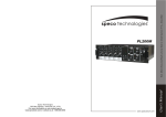
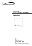
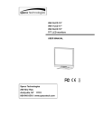
INSTRUCTION
MANUAL
P-30FACC 30 WATT RMS
P-30FACD 30 WATT RMS
P-60FACC 60 WATT RMS
P-60FACD 60 WATT RMS
WARNING: TO PREVENT FIRE
OR SHOCK HAZARD, DO NOT
EXPOSE UNITS NOT
SPECIFICALLY DESIGNED FOR
OUTDOOR USE TO RAIN OR
MOISTURE.
RISK OF ELECTRIC
SHOCK, DO NOT OPEN!
CAUTION: TO REDUCE THE RISK
OF ELECTRIC SHOCK, DO NOT
OPEN COVER. NO USER
SERVICEABLE PARTS INSIDE.
REFER SERVICING TO QUALIFIED
SERVICE PERSONNEL.
PRECAUTIONS
WARNING: REMOVAL OF THE
COVER SHOULD ONLY BE PERFORMED BY QUALIFIED SERVICE
PERSONNEL - NOT USER SERVICEABLE. THE UNIT SHOULD
ALWAYS BE UNPLUGGED BEFORE
REMOVING THE COVER, AND
REMAIN UNPLUGGED WHILE THE
COVER IS REMOVED.
1.Unpacking
After removing the amplifier from the carton, inspect for any exterior damage to
the unit. If damage is noted, notify the carrier at once so that a claim can be
justified. Save all packing material. This is important when the claim is
processed.
2.Ventilation
To offset heat generated by the unit, it is necessary to provide ample ventilation
around the unit. Avoid blocking or impeding the ventilation holes in the unit. To
prevent unnecessary problems, install the unit in a place free from any
vibrations, direct sunlight, humidity or dust circulation.
3.Avoid spilling liquids or allowing materials to enter the cabinet
If the unit gets wet or any foreign material enters the cabinet, immediately
disconnect the A.C. line cord and consult your dealer or qualified technician.
200 NEW HIGHWAY, AMITYVILLE, NY11701
PHONE : 1-800-645-5516, 631-957-8700 IN METRO NY
http://www.specotech.com
IMPORTANT SAFETY INSTRUCTIONS
1. Read these instructions.
2. Keep these instructions.
3. Heed all warnings.
4. Follow all instructions.
5. Do not use this apparatus near water.
6. Clean only with dry cloth.
7. Do not block any ventilation openings. Install in accordance with the manufacturer’s
instructions.
8. Do not install near any heat sources such as radiators, heat registers, stoves, or
other apparatus (including amplifiers) that produce heat.
9. Do not defeat the purpose of the polarized or grounding-type plug. A polarized plug
has two blades with one wider that the other. A grounding type plug has two blades
and a third grounding prong. The wide blade or the third prong are provided for your
safety. If the provided plug does not fit into your outlet, consult an electrician for
replacement of the obsolete outlet.
10. Protect the power cord from being walked on or pinched particularly at plugs,
convenience receptacles, and the point where the exit from the apparatus.
11. Only use the attachments/accessories specified by the manufacturer.
12. Use only with the cart, stand, tripod, bracket, or table specified by the manufacturer,
or sold with the apparatus. When a cart is used, use caution when moving the
cart/apparatus combination to avoid injury from tip-over.
13. Unplug this apparatus during lightning storms or when unused
for long periods of time.
14. Refer all servicing to qualified service personnel. Servicing is
required when the apparatus has been damaged in any way
such as power supply cord or plug is damaged, liquid has
been spilled or objects have fallen into the apparatus, the apparatus has been
exposed to rain or moisture, does not operate normally, or has been dropped.
15. Apparatus shall not be exposed to dripping or splashing and no objects filled with
liquids, such as vases, shall be placed on the apparatus.
16. Warning – To reduce the risk of fire or electric shock, do not expose this apparatus
to rain or moisture.
17. Apparatus shall not be exposed to dripping or splashing and no objects filled with
liquids, such as vases, shall be placed on the apparatus.
18. Caution – Use of any controls or adjustments or performance of procedures other
than those specified herein may result in hazardous radiation exposure.
2
Controls and Connections
FRONT PANEL
FACC
19
17 16 15
18
EJECT
AUTO-REVERSE
Background Music Cassette Player
1
2
3
4
5
6
7
8
FACD
1) MIC-1 input jack (1/4’’phone jack)
2) Output level indicator
3) MIC-1 Volume control
4) MIC-2 Volume control
5) MIC-3 Volume control
6) MIC-4 Volume control
7) Line input selector switch
8) Line input volume control
9) Bass control
10)Treble control
14 13
9
PROGRAM
10
11
12
20
11) Master volume control
12) Power on/off switch with LED indicator
13) Zone 4 selector switch
14) Zone 2 selector switch
15) Zone 1 selector switch
16) Zone 3 selector switch
17) All zone selector switch
18) Auto – reverse cassette player unit
19) FM/AM tuner unit
20) CD player unit
3
REAR PANEL
FACC
8
10
9
11
12
1
13
15
14
2
16
3
17
18 19 20 21 22
5
4
6
23
7
FACD
8
9
10
11
1
12
13
15
14
2
1) Speaker outputs
2) Ground
3) FM antenna input
4) AM antenna input
5) MOH output terminals*
6) Manual muting terminals
7) TEL/PAGING input terminals (Balanced)**
8) Zone 1 output terminals
9) Zone 2 output terminals
10) Zone 3 output terminals
11) Zone 4 output terminals
12) AC input cable receptacle
*MOH = Music on hold
**TEL/PAGING= Connection input terminals for
3
16
17
4
18 19 20 21 22
5
6
23
7
13) AC 115V/230V selector switch BENEATH
SMALL METAL COVER(SEE ABOVE).
14) AC fuse holder
15) LINE output RCA jacks
16) AUX input RCA jacks
17) MIC-4 (XLR connector) input
18) MIC-3 (XLR connector) input
19) MOH output level control*
20) MIC-1 VOX on/off switch
21) MIC-2 (XLR connector) input
22) TEL/PAGING input level control**
23) MIC-1 (XLR connector) input
**TEL/PAGING is not to be connected directly to a
telephone circuit or TNV circuit.
general or emergency paging.
4
FRONT PANEL
1) MIC-1 input jack (1/4’’ phone jack). Accepts a balanced low impedance microphone with
a standard 1/4’’phone plug.
2) Output level indicator. Indicates power output. Do not overload amp.
3) MIC-1 Volume control. Adjusts audio level of MIC-1.
4) MIC-2 Volume control. Adjusts audio level of MIC-2.
5) MIC-3 Volume control. Adjusts audio level of MIC-3.
6) MIC-4 Volume control. Adjusts audio level of MIC-4.
7) Line input selector switch. Allows for selection of high impedance AUX input or music
source from tuner, CD player or cassette player.
8) Line input volume control. Adjusts audio level of line input.
9) Bass control. Low frequency tone control.
10) Treble control. High frequency tone control.
11) Master volume control. Controls all volume levels simultaneously.
12) Power on/off switch with LED indicator. Illuminates when power is on.
13) Zone 4 selector switch. Allows for selection the Zone 4 paging with 70V or 25V line
output. (internally selected, see page 10)
14) Zone 2 selector switch. Allows for selection the Zone 2 paging with 70V or 25V line
output. (internally selected, see page 10)
15) Zone 1 selector switch. Allows for selection the Zone 1 paging with 70V or 25V line
output. (internally selected, see page 10)
16) Zone 3 selector switch. Allows for selection the Zone 3 paging with 70V or 25V line
output. (internally selected, see page 10)
17) All zone selector switch. Allows for selection the All zone paging with 70V or 25V line
output. (internally selected, see page 10)
18) Auto – reverse cassette player unit. (see page 7)
19) FM/AM tuner unit. (see page 8)
20) CD player unit. (see page 7)
REAR PANEL
1) Speaker outputs. Speaker lines must be connected to “COM” and one (and only one) of the
remaining screw terminals.
2) Ground. Cabinet enclosure unit ground.
3) FM antenna input. Connect supplied dipole antenna using supplied 75
matching
4)
5)
6)
7)
transformer or coaxial cable to the antenna connector.
AM antenna input. Connect the supplied wire loop antenna to the AM spring loaded
terminals.
MOH output terminals. Provided two MOH outputs 600 Ohm, 1 Volt and 8 Ohm, 1 Watt.
Manual muting terminals. Provides manual contact closure muting of the AUX and MIC-2~4
inputs during paging.
TEL / PAGING balanced input terminals. Accepts a balanced telephone paging signal.
5
8 ~ 11) Zone 1~4 output terminals. In addition to the normal 70V and 25V line outputs, there
are four groups of 70V or 25V (internally selected, see page 10) line terminals for 4 zones
which can be selected using the push buttons on the front panel.
12) AC input cable receptacle . AC inlet with three pin socket for use of either 115VAC or
230VAC selected by slide switch on rear panel (see page 4). The amplifier is factory set at
115VAC main voltage. (230VAC operation requires AC plug adaptor.)
13) AC 115V/230V selector switch (Beneath small metal cover, see drawing of rear panels
on page 4). Allows for selection of either 115VAC or 230VAC operation. For operating on
230VAC main voltage, remove the small metal cover with a screw driver and slide the
voltage select switch’s actuator from 115VAC(factory set, left side) to 230VAC(right side),
then re-mount the small metal cover with the 230VAC sticker showing on back of small
metal cover and tighten screws.
14) AC fuse holder. Line fuse for the amplifiers:
P–30FACC and P–30FACD
- 2A for 115VAC
- 1A for 230VAC
P–60FACC and P–60FACD
- 3A for 115VAC
- 1.6A for 230VAC
15) LINE output RCA jacks. This booster output supplies the input signal to an additional power
amplifier. This signal is after tone control and master volume control. In this fashion, very large
systems requiring more power can be accommodated.
16) AUX input RCA jacks. High impedance input available with parallel RCA jacks (for stereo
accessories combined for mono.)
17) MIC-4 (XLR connector) input. Accepts a balanced low impedance microphone signal
with an XLR connector.
18) MIC-3 (XLR connector) input. Accepts a balanced low impedance microphone signal
with an XLR connector.
19) MOH output level control. Controls volume of MOH output. (Music on hold)
20) MIC-1 VOX on/off switch. Allows for disabling of MIC-1 input VOX muting of the MIC-2~4
and AUX input during paging. This allows for multiple MIC paging/operation.
21) MIC-2 (XLR connector) input. Accepts a balanced low impedance microphone signal
with an XLR connector.
22) TEL/PAGING input level control. Controls audio level of telephone input.
23) MIC-1 (XLR connector) input. Accepts a balanced low impedance microphone signal
with an XLR connector.
Note: Screw terminal designations: G-GND, HOT-Signal positive, COM-Signal negative/common.
6
CD PLAYER UNIT
1. CD display
2. Repeat button
3. Random button
4. Program button
5. CD power on/off button
6. Previous track button
7. Next track button
8. Play/pause button
9. Stop/eject button
CD PLAYER OPERATION
1. Select CD mode with LINE selector switch.
2. Press POWER button on CD player.
3. Load disc (label side up) into player and PLAY begins automatically.
4. Press PAUSE button and symbol ll appears in the display and play is suspended.
Press PAUSE button again to resume play.
5. Pressing
button selects the next track and
button the previous track.
6. Press the RANDOM button, random appears in the display and tracks are played in random
sequence.
appears on the display and the current track
7. Press the REPEAT button once and symbol
is repeated. When the button is pressed twice the symbol
appears and indicates repeat
play of the disc. To cancel these functions press the REPEAT button again.
8. Programming the CD player – in STOP mode.
(a) Press the PROGRAM button
(b) Use the next
or previous
button to select a track.
(c) Press REPEAT button to activate memory of the selected tracks in your program. Repeat
stages (b) and (c) to continue programming.
(d) Press the PLAY button to start the program (Note: The program repeats itself until the CD
player is stopped).
CASSETTE PLAYER UNIT
1. Eject switch
2. Cassette slot
3. Direction indicators
4. Fast wind/program buttons
CASSETTE PLAYER OPERATION
The cassette mechanism is an auto-reverse type which detects when the end of the tape has
been reached and will automatically reverse the direction of the tape and play the opposite side of
the cassette. This function will continue until the cassette is remove from the player.
NOTE: Due to the abrasive nature of cassette tapes some oxide from the tape will be deposited
on to the cassette heads and rollers and therefore the mechanism will need cleaning at regular
intervals. Cleaning cassettes can be purchased from most good hi-fi stores. DO NOT use C120 (120
minute) cassettes.
7
INSERTING A CASSETTE
The cassette should be inserted edge first with the exposed tape on the right-hand side, push the
cassette into the mechanism until the cassette drops into position.
REMOVING THE CASSETTE
Firmly press the eject button, the cassette will be automatically ejected.
FAST WIND
The cassette can be fast wound in either direction (forward or reverse) to any position on the tape by
pressing and holding one of the fast wind buttons and will be stopped automatically after releasing the
button.
DIRECTION CHANGE
The side of the cassette currently playing can be reversed to play the other side of the cassette at
any time by pressing both fast wind buttons simultaneously.
FM/AM TUNER UNIT
4
1. Tuner display
2. Memory button
3. Shift button
4. FM/AM selection button
5. Frequency Up / Down button
6. Scan button
7. Set memory button
FM/AM TUNER
5
6
7
FUNCTION
MEMORY
1
TUNER OPERATION
2
3
For FM reception connect the supplied dipole antenna and 75
adaptor or an outdoor antenna
using 75
coaxial cable to the connector at the rear of the unit. (see page 4)
For AM reception connect the supplied antenna to the AM spring loaded terminals.
1. Select TUNER mode with the Line selector switch.
2. Select FM or AM.
3. Use the UP/DOWN buttons to set a frequency station manually or the SCAN button to
automatically search for the desired station.
4. To program a station press the MEM (Memory) button.
5. Press a MEMORY button (M1 to M5) or SHIFT button and memory button (M6 to M10) to store
a frequency.
FEDERAL COMMUNICATIONS COMMISSION INTERFERENCE STATEMENT
This equipment has been tested and found to comply with the limits for a Class B digital device,
pursuant to Part 15 of the FCC Rules. These limits are designed to provide reasonable protection
against harmful interference when the equipment is operated in a commercial environment. This
equipment generates, uses and can radiate radio frequency energy and, if not installed and used in
accordance with the instructions manual, may cause harmful interference to radio communications.
Operation of this equipment in a residential area is likely to cause harmful interference in which case
the user will be required to correct the interference at his own expense.
8
FCC CAUTION: To assure continued compliance, (example-use only shielded interface cables
when connecting to computer or peripheral devices). Any changes or modifications not expressly
approved by the party responsible for compliance could void the user’s authority to operate this
equipment.
OVERCOMING GROUND LOOP PROBLEMS
If the amplifier is mounted in a rack unit (Use rack mount part # PBM-RK2), or is used with
equipment having its own ground, it is necessary to ensure that ground loops and the associated
problems of hum on the output signal are not introduced by the ground wiring. (see warning)
WARNING
To overcome this problem if it occurs, the electrical and the mechanical ground on the amplifier
may be separated by completely removing the wire connecting the power source to ground.
CONSULT AN ELECTRONICS TECHNICIAN TO ACCOMPLISH THIS TO AVOID POTENTIAL
PERSONAL INJURY OR A HAZARDOUS CONDITION.
SPEAKER CONNECTION
The rear panel of the amplifier contains a 7 screw terminal strip for connection of speakers.
BE CAREFUL TO CONNECT SPEAKERS PROPERLY, see impedance and line voltage instructions
below.
The speaker lines are to be connected directly between the appropriate COM terminal on the 7 screw
terminal strip and the terminal corresponding to the impedance of the speaker(s) or of the line voltage
selected. (70V or 25V)
For 4, 8 and 16 OHM CONNECTIONS (refer to figure 3).
Connect the cables to the terminals on the 7 screw terminal strip provided. Use the screw terminals
which correspond to the impedance of the speaker(s). One lead must always be connected to the
COM. This is just an example. If in doubt consult a qualified technician.
(+)
(+)
(+)
TWO 8 SPEAKERS
(IN PARALLEL)
TWO 4 SPEAKERS
(IN SERIES)
FIGURE 3
9
(+)
CN905
For 25V and 70V CONSTANT VOLTAGE LINE CONNECTIONS
(refer to figure 4).
IMPORTANT NOTICE: When the 25V and 70V constant line voltages are used, a line
matching transformer must be used with each speaker. All
transformers must be connected in parallel.
Jumper positions for
70V or 25V selection.
70V
25V
HOW TO CONNECT LINE MATCHING TRANSFORMERS IN PARALLEL
(25 VOLT LINE OR 70 VOLT LINE)
ALWAYS CONNECT LINE TRANSFORMERS IN PARALLEL
NEVER CONNECT LINE TRANSFORMERS IN SERIES
SP1
SP1
SPn
SPn
70V Transf.
25V Transf.
FIGURE 4
SPEAKER IMPEDANCES:
Speaker impedance taps for 4, 8 and 16 Ohm speakers are provided on a terminal strip on the rear
panel of the unit. Also, outputs for 25V and 70V constant line voltage are provided. To connect the
power output directly to a speaker or PA horn or a combination of speakers and/or PA horns which
have a resulting voice coil impedance of 4,8 or 16 Ohm, connect to the COM and the proper
impedance tap on the terminal strip. Be sure the speaker(s) or PA horn(s) is capable of handling a
reasonable power output from the amplifier or permanent damage to the speaker(s) or PA horn(s) may
result. Also, be careful not to overload the amplifier with too many speakers or PA horns. If it is
desired to use a number and variety of speakers, the speakers must be arranged in various series or
parallel arrays to provide proper impedance matching or the 25V or 70V constant line voltage must be
used (parallel connection only). If you are not familiar with impedance matching, consult a professional
installer or technician for advice. If the 25V or 70V constant line voltages are used, a line matching
transformer must be used with each speaker. Again do not overload or use incompatible speakers.
Line transformers are the preferred method for multi-speaker installation.
10
CABLE REQUIREMENTS
Output cabling need not be shielded in most cases and should be of sufficient gauge to minimize
losses due to the resistance of the wire over long runs (insertion loss). Cable thinner than 18
gauge is not recommended. Long runs require 16 gauge or heavier.
In some cases, where the output cable is run in close proximity to unshielded intercom cables,
electrical cables, radio transmission antennas or other sources of interference or when the
amplifier is being used for paging from a telephone system, the amplifier may require shielded
output cabling to prevent audio feedback or interference.
PRIORITY PAGE:THE AMPLIFIER FEATURES A VOICE ACTIVATED PRIORITY PAGE CIRCUIT
AND AUTOMATICALLY MUTES ALL PROGRAM MATERIAL (TUNER/TAPE/CD, ETC.) FROM THE
AMPLIFIERS OUTPUT AND PERMITS MICROPHONE # 1 AND THE TELEPHONE INPUT TO
OVERRIDE FOR PAGING ANNOUNCEMENTS.
TELEPHONE LINE: A TELEPHONE LINE INPUT OF 600 OHMS IS PROVIDED.
THERE ARE MANY OTHER FEATURES OFFERED. PLEASE READ MANUAL COMPLETELY.
WHENEVER IN DOUBT ABOUT INSTALLATION, CONSULT WITH A PROFESSIONAL
INSTALLER OR TECHNICIAN OR PERSONAL INJURY, DAMAGE TO THIS AMPLIFIER
AND/OR SPEAKERS MAY RESULT AND YOUR WARRANTY MAY BE VOIDED.
PHANTOM POWER JUMPER POSITIONING
These adjustments are to be made by qualified technical personnel – Be
certain unit is disconnected from A/C power source prior to removing unit’s
cover or electrical shock or injury may result. The unit provides a Phantom
Power DC 15V for electret condenser microphone use.
Jumper location is to enable (ON) or disable (OFF) Phantom Power feature.
Note: Units come with Phantom Power enable (ON).
ON
OFF
JUMP-4
(MIC-4)
ON
OFF
ON
OFF
(MIC-1)
ON
OFF
JUMP-3
JUMP-1
(MIC-2)
(MIC-3)
11
Determining Your Amplifier Needs
for Sound Systems
Wattage Tap Requirement Chart
Set
Wattage
Taps
Step 1: Fill out Wattage Tap Requirement Chart (to right)
determining the number of speakers that will
be used at each wattage tap for the amplifier.
Ex A)
5
60
30
20
15
10
7.5
5
4
3.75
2.5
2
1.50
1.25
1.00
0.50
0.25
0.125
Step 2: Multiple the number of speakers by each wattage
tap to determine Total Wattage Requirement per
Tap setting (See Ex A).
Step 3: Add all the figures in shaded area to determine
the total Wattage Requirement for the amplifier.
Step 4: Match total Wattage Requirement to the bottom
chart "Recommended Amplifier Wattage Chart"
to determine acceptable RMS Wattage your
amplifier should have.
Step 5: Repeat this process for each amplifier system
required.
Number of
Speakers at
Set Tap
Total Wattage
Requirement per
Tap Setting
X
10
_____________
=
50
_____________
X
X
X
X
X
X
X
X
X
X
X
X
X
X
X
X
X
_____________
_____________
_____________
_____________
_____________
_____________
_____________
_____________
_____________
_____________
_____________
_____________
_____________
_____________
_____________
_____________
_____________
=
=
=
=
=
=
=
=
=
=
=
=
=
=
=
=
=
_____________
_____________
_____________
_____________
_____________
_____________
_____________
_____________
_____________
_____________
_____________
_____________
_____________
_____________
_____________
_____________
_____________
Total Sum of Shaded Area
Represents Total Wattage
Requirement
Recommended Amplifier Wattage Chart
If Sum Wattage Total is 12 Watts or Less
If Sum Wattage Total is between 13 and 24 Watts
If Sum Wattage Total is between 25 and 48 Watts
If Sum Wattage Total is between 49 and 96 Watts
If Sum Wattage Total is between 97 and 204 Watts
If Sum Wattage Total is between 205 and 216 Watts
If Sum Wattage Total is between 217 and 240 Watts
If Sum Wattage Total is between 241 and 288 Watts
Acceptable Amplifier RMS Wattage
15 Watt
30 Watt 60 Watt 120 Watt
X
X
X
X
X*
X
X
X
X*
X*
X
X
X*
X*
X*
X
X*
X*
X*
X*
X*
X*
X*
X*
X*
X*
* RMS Amplifier used in conjuction with Speco Technologies’ P-240A Power Booster Amp
For more information contact us at:
Speco Technologies 200 New Highway, Amityville, NY 11701 Web: www.specotech.com
Toll Free: 1-800-645-5516 In Metro NY: 631-957-8700 Fax: 631-957-9142 or 631-957-3880
12
_____________
Technical Specifications
Type
Model
Supply
P - 30FACC
Main Voltage
Output power
Music Max
RMS Rated
Outputs
Inputs
Frequency response
Total harmonic distortion
Signal to noise ratio
Tone Controls
Controls
Indicators
AC power consumption
Priority (VOX)
Dimensions ( H x W x D )
Weight
Color
Mounting options
Music Source
PA Amplifier with Music Sources
P - 30FACD
P - 60FACC
AC 115V/230V ,50/60Hz
10% , Switchable
45W
45W
90W
90W
30W
30W
60W
60W
Speaker outputs:
MOH output :
ZONE outputs:
4 ,8 ,16 ,25V,70V
8 1Watt / 600 ,1V balanced. 25V or 70V 4 zones + All
Line out:600 ,1V
MIC-1:250 ,1mV,balanced with phantom power selectable (Jump 1)
MIC-2:250 ,1mV,balanced with phantom power selectable (Jump 2)
See page 11
MIC-3:250 ,1mV,balanced with phantom power selectable (Jump 3)
MIC-4:250 ,1mV,balanced with phantom power selectable (Jump 4)
AUX:47K ,200mV,unbalanced.
TEL: 0.1~1V,600 ,adjustable, balanced
60~15K Hz at 3dB
Less than1% at 1KHz, at rated power
All Volume Controls C.C.W : 75dB below rated power.
MIC-1~MIC-4 : 60 dB below rated power
AUX : 70 dB below rated power
TEL : 70 dB below rated power
Bass : 10 dB at 100Hz
Treble:
10 dB at 10KHz
MIC-1~MIC-4 volume controls
Line(AUX/Tuner/CD/Cassette) volume control
Master volume control
TEL input level control
MIC-1 VOX on/off switch
MOH output level control
Tone controls (Bass, Treble)
Zone1, Zone 2, Zone 3, Zone 4 and All zone
AC 115V / 230V Voltage Selector Switch.
Output level meter (3 LEDS)
100 VA
100 VA
170 VA
170 VA
Priority level (Using for MIC-1, the XLR connector or phone jack)
TEL / Emer MIC-1 MIC-2 MIC-3 MIC-4 AUX / Tuner/ CD-Tape
3
2
1
1
1
1
3.5”(H) x 16.9”(W) x 11.8”(D)
Approx : 15.4 lbs
Approx :15.4 lbs
Approx : 18.7 lbs
Approx : 18.7 lbs
Black
Table top or, 19” rack mountable(Use # PBM-RK2 rack mount bracket)
TM-2 : FM / AM Digital Tuner TM-2 : FM / AM Digital
TM-2 : FM / AM Digital Tuner TM-2 : FM / AM Digital
Unit
Tuner Unit
CP-2 : Auto-reverse cassette CD-2 : CD player unit
player unit
CP-2
CD-2 CD Player Unit
CD Player Unit
CD-2
< 0.1 %
>80 dB
850 mV
Eject/stop, Pause/play, Next, Previous,
Power, Program, Random, Repeat.
Auto-Reverse Cassette Player Unit
Type
Model
WOW / Flutter
Tape Speed
Frequency response
S/N
Distortion
Output
Functions
TM-2 FM/AM Digital Tuner Unit with 20 Programmable Presets
Frequency response
FM / AM Digital Tuner Unit
TM-2
FM: 87.5~108 MHz
AM: 522~1620 KHz
FM: 2ìV ( 26 dB S /N )
AM: 30ìV ( 20 dB S /N )
30Hz ~ 15 KHz (+1 / -3 dB)
Distortion
S/N
Output
<1%
>63 dB (1 mV, FM )
500 mV (0~1V adjustable)
Functions
FM/AM, Down, Up, Scan, Mem
M1, M2, M3, M4, M5, Shift
Type
Model
Tuning range
Sensitivity
Tuner Unit
Unit
CP-2 : Auto-reverse cassette CD-2 : CD player unit
player unit
Type
Model
Distortion
S/N
Output
Functions
P - 60FACD
13
Auto-Reverse Cassette Player Unit
CP-2
0.45 %
2940 ~ 3090 Hz
125Hz ~ 6.3KHz ± 4dB
40 dB
3%
500 mV (0~1V adjustable)
Eject, Auto-reverse, Program
5
5
5
5
$
$
$
),3'
)4'
/,'2
)3'2 &
!"#
%
6
$
!"#
&
$
!"#
&
6
$
$
6
$
6
$
$
$
5
'()*)!+
"'',! ./0+12 (
$%&
"#
!
!
!
"&7,
/"8,
2&,5
6"7,5 6
!
"#
$%&
/!
'
(
!
(
+
!$)*
$)*
6
6
,-"."$#
+
/),,&$0
123#45 (