1
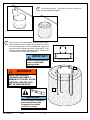
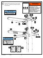
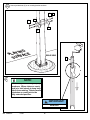
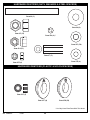
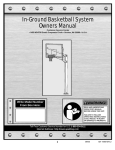
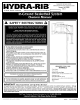
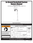
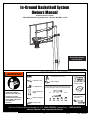
In-Ground Basketball System
Owners Manual
Customer Service Center
• N53 W24700 South Corporate Circle • Sussex, WI 53089 • U.S.A.
Write Model Number
From Box Here:
WARNING!
REQUIRED TOOLS AND MATERIALS:
• 3 Capable Adults
• (2) Stepladders 8 ft. (2.4 m)
•
• Carpenter’s Level
• Safety Goggles
• Container to Mix
• 15’ Tape Measure
READ AND UNDERSTAND
OPERATOR'S MANUAL
BEFORE USING THIS UNIT.
FAILURE TO FOLLOW
OPERATING INSTRUCTIONS
COULD RESULT IN INJURY
OR DAMAGE TO
PROPERTY.
• (2 each) Wrenches and/or Socket Wrenches and
Sockets (Deep-Well Sockets are Recommended).
• Shovel & Post Hole
Digger
3/8"
1/2"
9/16"
3/4"
15/16"
• Optional: Large &
Small Adjustable
Wrenches
• Phillips Screwdriver
3/8"
1/2"
9/16"
3/4"
15/16"
• (1) Utility Knife
Toll-Free Customer Service Number for U.S: 1-800-558-5234 Canada Only: 1-800-284-8339
Internet Address: http://www.hydra-rib.com
© COPYRIGHT 2006 by SPALDING
1
02/06
ID# M880961
IMPORTANT! WRITE MODEL NUMBER FROM BOX ONTO PAGE 1 OF THIS OWNERS MANUAL
SAFETY INSTRUCTIONS
WARNING
FAILURE TO FOLLOW THESE SAFETY INSTRUCTIONS MAY RESULT IN
SERIOUS INJURY, PROPERTY DAMAGE AND WILL VOID WARRANTY.
Read and understand warnings listed
below before using this product.
Owner must ensure that all players know and
follow these rules for safe operation of the system.
To ensure safety, do not attempt to assemble this system without following the
instructions carefully. Proper and complete assembly, use and supervision is
essential for proper operation and to reduce the risk of accident or injury. A
high probability of serious injury exists if this system is not installed,
maintained, and operated properly. Check entire box and inside all packing
material for parts and/or additional instructional material. Before beginning
assembly, read the instructions and identify parts using the hardware identifier
and parts list in this document.
• If using a ladder during assembly, use extreme caution.
• Three (3) people are recommended for this operation.
• Seat the pole sections properly. Failure to do so could allow the pole sections to
separate during play.
• Before digging, contact utility company to locate underground power cables, gas,
and water lines. Ensure there are no overhead power lines within 20 ft. (7 m) radius
of pole location.
• Climate, corrosion, excessive use, or misuse could result in system failure.
• If technical assistance is required, contact Customer Service.
• Minimum operational height is 6' 6" (1.98 m) to the bottom of backboard.
• This equipment is intended for home recreational use only and NOT
excessive competitive play.
• Read and understand the warning label affixed to pole.
• The life of your basketball pole depends on many conditions. The climate,
placement of the pole, the location of the pole, exposure to corrosives such as
pesticides, herbicides or salts are all important.
• Adult supervision is recommended when adjusting height.
• Serious injury could occur if teeth/face come in contact with backboard, net, or rim.
Failure to follow these warnings may
result in serious injury and/or
property damage.
Owner must ensure that all players know and follow these rules
for safe operation of the system.
• DO NOT HANG on the rim or any part of the system including
backboard, support braces or net.
• During play, especially when performing dunk type activities,
keep player's face away from the backboard, rim and net.
Serious injury could occur if teeth/face come in contact with
backboard, rim or net.
• Do not slide, climb, shake or play on base and/or pole.
• When adjusting height or moving system, keep hands and
fingers away from moving parts.
• Do not allow children to move or adjust system.
• During play, do not wear jewelry (rings, watches, necklaces,
etc.). Objects may entangle in net.
• Keep organic material away from pole base. Grass, litter, etc.
could cause corrosion and/or deterioration.
• Check pole system for signs of corrosion (rust, pitting,
chipping) and repaint with exterior enamel paint. If rust has
penetrated through the steel anywhere, replace pole
immediately.
• Check system before each use for proper ballast, loose
hardware, excessive wear and signs corrosion and repair
before use.
• Check system before each use for instability.
• Never play on damaged equipment.
• Keep pole top covered with cap at all times.
• See instruction manual for proper installation and
maintenance.
Most injuries are caused by misuse and/or not following instructions.
Use caution when using this system.
In the U.S.: 1-800-558-5234
In Canada: 1-800-284-8339
For more information on assembly, placement, proper use and maintenance,
visit The American Basketball Council website at http://www.smarthoops.com.
In the U.S.: 1-888-713-5488
In the U.S.: 1-800-334-9111
In the U.S.: 1-800-558-5234
In Canada: 1-800-284-8339
ID#: 588000
WARRANTY CARD:
Please remember to complete your product registration form either
on-line at:
www.huffysports.com/customer_support/product_registration
or mail-in the enclosed postcard.
31
ID# M880961
02/06
2
05/05
1.
Ensure ground is level with playing
surface, then dig pole hole.
PLAYING
SURFACE
WARNING!
24" (61 cm)
36" (91.4 cm)
GROUND
SURFACE
CONTACT UTILITIES
BEFORE DIGGING.
2.
Install nut (2) to J-bolt (1) as
shown. Repeat procedure for
other three J-bolts (1).
2
2-1/2”
(6.35 cm)
2
3
IMPORTANT!
Make sure nuts are 2-1/2”
(6.35cm) from top of
J-Bolts.
1
2
NOTE:
Make sure J-bolts (1) are
in the illustrated position.
3.
Install threaded ends of J-bolts (1) through holes in
mounting plate (3) and secure as shown.
1
NOTE:
Nuts on the top of plate are
used for leveling the pole after
system is fully assembled.
3
02/06
ID# M880961
4.
5.
Fill hole with concrete. Tamp down concrete to release air
pockets and build drainage hill.
Insert J-bolts (1) from mounting plate (3) into cement as shown.
Move assembly around to release any air pockets in cement,
then rest mounting plate on cement drainage hill. Apply some
pressure to level mounting plate on top of drainage hill. Level
mounting plate and square with playing surface. Clean off any
excess cement on mounting plate at this time.
IMPORTANT!
PLAYING SURFACE
Front of mounting plate (3)
must be parallel with
playing surface.
3
WARNING!
DO NOT PROCEED UNTIL
CONCRETE HAS CURED! A
MINIMUM OF 72 HOURS. ALLOW
ADDITIONAL TIME FOR COLD,
WET OR HUMID WEATHER.
1
IMPORTANT!
Check leveling of mounting
plate several times with
carpenter’s level while
concrete is curing.
ID# M880961
02/06
4
WARNING!
THREE CAPABLE ADULTS
REQUIRED FOR THIS
PROCEDURE. FAILURE TO
FOLLOW THIS WARNING
COULD RESULT IN
SERIOUS INJURY AND/OR
PROPERTY DAMAGE.
6.
5
Upright pole (5). Assemble lower pole flange
onto protruding J-bolts (1) as shown. The flange
will then rest on the nuts (2).
IMPORTANT!
Holes in pole must be
parallel with playing
surface.
PLAYING SURFACE
7.
Secure pole (5) flange to mounting plate (3)
as shown. Tighten completely.
NOTE:
Position crank jack
mounting as shown.
5
2
2
6
6
6
2
6
6
6
6
1
1
3
5
02/06
G
IN E
AY AC
PL RF
SU
2
6
ID# M880961
8.
WARNING!
Beginning with upper support arm (8) secure support
arms to pole. Continue by securing lower support
arm (9) as shown.
THREE CAPABLE ADULTS
REQUIRED FOR THIS
PROCEDURE. FAILURE TO
FOLLOW THIS WARNING
COULD RESULT IN
SERIOUS INJURY AND/OR
PROPERTY DAMAGE.
IMPORTANT!
Do Not Over Tighten.
28 27
27
28
14
28
13
8
13
12
28
28 27
9
27
28
13
14
28
13 28
12
7
IMPORTANT!
7
33
Bushing
types are
identified
with a letter.
27
ID# M880961
02/06
28
6
14
9.
Secure backboard to support arms (8 and 9) as
shown.
IMPORTANT!
Bushing
types are
identified
with a letter.
IMPORTANT!
Do Not Over Tighten.
28
13
28
28
13
27
14
28
14
13
8
10
10
27
13
13
28
28
14
10
27
27
13
9
28
7
02/06
ID# M880961
10.
Secure jack brackets (21) to to mounting bracket as shown.
13 14
11
13
21
21
G
N
I
Y
PLA RFACE
SU
11.
REAR VIEW
20
NOTE:
Position U-joint of crank jack (20)
as shown. Where tubes on crank
jack join, hold steady to keep both
tubes from rotating. Rotate handle
clockwise on crank jack to the
fully extended position.
IMPORTANT!
Hold Here.
ID# M880961
02/06
8
12.
A. Insert spacer (4) through spacer of screw jack as shown.
WARNING!
B. Install crank jack (20) U-joint to lower support arm (9) as shown.
TWO CAPABLE ADULTS
REQUIRED FOR THIS
PROCEDURE. FAILURE TO
FOLLOW THIS WARNING COULD
RESULT IN SERIOUS INJURY
AND/OR PROPERTY DAMAGE.
A.
4
20
20
9
IMPORTANT!
Bushing
types are
identified
with a letter.
B.
28
28
14
9
27
12
28
28 13
REAR VIEW
13
28
ING E
Y
A
L
P
AC
SURF
20
IMPORTANT!
Do Not Over Tighten.
9
02/06
ID# M880961
13.
Rotate jack handle until jack (20) aligns with jack brackets (21). Secure crank jack (20)
to jack brackets (21) as shown.
WARNING!
TWO CAPABLE ADULTS
REQUIRED FOR THIS
PROCEDURE. FAILURE TO
FOLLOW THIS WARNING COULD
RESULT IN SERIOUS INJURY
AND/OR PROPERTY DAMAGE.
20
15
14
15
13
34
13
21
REAR VIEW
NOTE:
Some adjustment will be necessary
to align the lower crank jack and
bushings to jack brackets (21).
ID# M880961
NG
02/06
10
14.
Set-up For Leftt Side
Set-up For Right Side
A. Apply height indicator
labels (18 and 19) to
height indicators (16).
16
16
7 8 9 10
7 8 9 10
78
0
91
7 8 9 10
18
78
0
91
10 9 8 7
10 9 8 7
19
7 8 9 10
B. Attach height indicators (16) to lower arm in areas as
shown by turning screws (17) into place with a phillips
screwdriver.
IMPORTANT!
Note Orientation of Height
Indicators: 10’ Mark Should
Face Away From Backboard.
16
16
78
9 10
7
10 9 8 7 8 9 10
7
10 9 8
17
17
ING E
Y
A
L
P
C
URFA
11
02/06
GN
ECAF IYALP
RU
ID# M880961
10
9
8
15.
Install net (30) to rim as shown.
A.
B.
D.
C.
30
16.
30
Attach rim assembly (29). For rim assembly, see
instructions included with rim.
23
29
Rim Assembly
24
25
25
Remove rim cover
prior to installing rim
assembly to board.
Refer To Instructions
Included With Rim
Hardware For Rim
Assembly.
ID# M880961
02/06
22
IMPORTANT!
Carefully cut and peel
protective film away from
board prior to attaching rim.
12
17.
Check leveling at this time. Pole (5) should
be level in all directions. After system is
leveled, completely tighten nuts (2) above
pole flange.
5
NOTE:
If adjustment is necessary, adjust
system by rotating the nuts (2)
between mounting plate (3) and
pole flange.
2
18.
Apply height adjustment label (31) to
front of pole as shown.
HR83008PoleGusset
31
13
REGULATION
RIM HEIGHT IS
10 FEET (3.05 m).
02/06
ID# M880961
32
19.
Secure pole pad (32) as
shown.
NOTE:
Pole pad may NOT be
included in this model.
MHE19.EPS
206239
Height Adjustment
20.
Rotate crank handle to raise or lower backboard.
NOTE:
If height adjustment is difficult to
operate, you may have over
tightened the areas indicated.
M83013.E
211560
ID# M880961
02/06
14
M83014.EPS
211560
PARTS LIST
Item Qty. Part No. Description
18
1
204739 Label, Height Indicator, Right
19
1
204740 Label, Height Indicator, Left
1
4
200573 J-Bolt, 1/2-13 x 24” Long
20
1
222880 Crank, Jack
2
12
265575 Nut, Hex, 5/8-11
21
2
908292 Bracket, Crank Jack Support
3
1
900661 Anchor Plate
22
4
203017 Nut, Hex, 3/8-16
4
1
220579 Spacer, 0.53 I.D. x 0.75 O.D. x 5” Long
23
2
205347 Bolt, Carriage, 3/8-16 x 3.5” Long
5
1
908310 Pole
24
2
200512 Bolt, Hex, Tap, 3/8-16 x 3.5” Long
6
8
200704 Washer, 5/8” x 1.5 O.D.
25
6
203309 Washer, Flat, 3/8”
7
2
205125 Spacer, 0.53 I.D. x 0.75 O.D. x 1.88” Long
26
4*
203300 Washer, 3/8 Locking,
8
1
908312 Support Arm, Upper
27
8
9
1
908311 Support Arm, Lower
28
20 204670C Bushing, Plastic
10
4
206271 Bolt, Hex Head, 1/2-13 x 2-1/2” Long
29
1
Rim
11
3
205516 Bolt, Hex Head, 1/2-13 x 5.75” Long
30
1
Net
12
3
205515 Bolt, Hex Head, 1/2-13 x 10.25” Long
31
1
13
20
202651 Washer, Flat, 1/2”
32
1
14
11
206340 Lock Nut, Hex 1/2-13
15
2
205082 Spacer, 0.53 I.D. x 0.75 O.D. x .38 Long
33
1
1
16
2
204735 Height Indicator
34
1
17
4
204733 Screw, #8 x .050” Long
204670A Bushing, Plastic
200685 Label, Height Adjustment
205600 Pole Pad, Hydra-Rib (May Not Be Included)
205600S Pole Pad, Spalding (May Not Be Included)
205515 Bolt, Hex, 1/2-13 x 10.25” Long
205076 Bolt, Hex, 1/2-13 x 5.5” Long
* You May Have Extra Parts With This Model.
Item Qty. Part No. Description
HARDWARE IDENTIFIER (BOLTS)
Item #24 (2)
Item #17 (4)
Item #10 (4)
Item #23 (2)
#206271 hex head bolt,1/2 x 2 1/2
Item #11 (3)
Item #33 (1)
15
02/06
ID# M880961
HARDWARE IDENTIFIER (NUTS, WASHERS & STEEL SPACERS)
Item #4 (1)
spacer 1/2 x 5 Long
Item #6 (8)
Item #2 (12)
Item #26 (4)*
Item #13 (20)
Item #14 (11)
Item #7 (2)
Item #25 (6)
Item #22 (4)
HARDWARE IDENTIFIER (PLASTIC & NYLON SPACERS)
Item #15 (2)
Item #27 (8)
Item #28 (20)
* You May Have Extra Parts With This Model.
ID# M880961
02/06
16