1
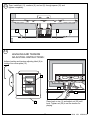
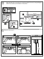
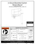
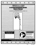
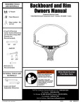
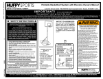
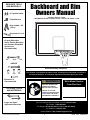
REQUIRED TOOLS
AND MATERIALS:
• 2 Capable Adults
• Tape Measure
Backboard and Rim
Owners Manual
Customer Service Center
• N53 W24700 South Corporate Circle • Sussex, WI 53089 • U.S.A.
• Step Ladder - 8ft.
(2.4 m)
• Carpenter’s Level
• (2 each) Wrenches
and/or Socket Wrenches
and Sockets (Deep-Well
Sockets are
Recommended).
1/2"
9/16"
3/4"
AND/OR
Adult Assembly Required.
1/2"
9/16"
3/4"
This manual, accompanied by sales receipt, should be saved and kept on hand as a
convenient reference, as it contains important information about your model.
• Extension is
Recommended.
OPTIONAL TOOLS
AND MATERIALS:
• Large and Small
Adjustable Wrenches
© COPYRIGHT 2006 by SPALDING
WARNING!
READ AND UNDERSTAND
OPERATOR'S MANUAL
BEFORE USING THIS UNIT.
Write Model Number
From Box Here:
FAILURE TO FOLLOW
OPERATING INSTRUCTIONS
COULD RESULT IN INJURY
OR DAMAGE TO PROPERTY.
Toll-Free Customer Service Number for U.S: 1-800-558-5234,
For Canada: 1-800-284-8339,
For Europe: 00 800 555 85234 (Sweden: 009 555 85234),
For Australia: 1-800-632 7921
Internet Address: http://www.huffysports.com
1
05/06 ID#
M7900412
SAFETY INSTRUCTIONS
FAILURE TO FOLLOW THESE SAFETY INSTRUCTIONS MAY RESULT IN SERIOUS INJURY, PROPERTY DAMAGE AND WILL VOID
WARRANTY.
Owner must ensure that all players know and follow these rules for safe operation of the system.
To ensure safety, do not attempt to assemble this system without following the instructions carefully. Proper and complete assembly,
use and supervision is essential for proper operation and to reduce the risk of accident or injury. A high probability of serious injury
exists if this system is not installed, maintained, and operated properly. Check entire box and inside all packing material for parts and/or
additional instructional material. Before beginning assembly, read the instructions and identify parts using the hardware identifier and
parts list in this document.
• Read and understand the warning label enclosed with hardware. It is the responsibility of the customer to mount
this label. It should be affixed to the pole, wall, or door near playing area, at a height between 4-6 feet (1.221.83M) above ground level and in a location visible to all players.
• During assembly, if using a ladder use extreme caution. Two people are recommended for this operation.
• If technical assistance is required, contact Customer Service.
• Serious injury could occur if teeth/face come in contact with backboard, net or rim.
• Minimum operational height should be 6’6” (2M) to the bottom of backboard.
Most injuries are caused by misuse and/or not following instructions.
Use caution when using this system.
For more information on assembly, placement, proper use and maintenance, visit The American Basketball Council
website at http://www.smarthoops.com.
NOTICE TO ASSEMBLERS
Adult Assembly Required. Dispose of ALL packaging materials promptly. As with all products, periodically
inspect for loose small parts.
Assembled unit MUST be filled with sand or water at ALL times.
ALL basketball systems, including those used for DISPLAYS, MUST be assembled and installed according
to instructions. Failure to follow instructions could result in SERIOUS INJURY. It is NOT acceptable to
devise a makeshift support system.
IMPORTANT!
Remove all contents from boxes.
Be sure to check inside pole sections;
hardware and additional parts are packed inside.
WARNING
Read and understand warnings listed
below before using this product.
Failure to follow these warnings may
result in serious injury and/or property
damage.
Owner must ensure that all players know and follow these rules
for safe operation of the system.
9
• DO NOT HANG on the rim or any part of the system including
backboard, support braces or net.
• During play, especially when performing dunk type activities,
keep player's face away from the backboard, rim and net.
Serious injury could occur if teeth/face come in contact with
backboard, rim or net.
• During play, do not wear jewelry (rings, watches, necklaces,
etc.). Objects may entangle in net.
• Check system before each use for loose hardware, excessive
wear and signs corrosion and repair before use.
• Never play on damaged equipment.
• See instruction manual for proper installation and
maintenance.
In the U.S.: 1-800-334-9111
In the U.S.: 1-800-558-5234
In Canada: 1-800-284-8339
In the U.S.: 1-800-558-5234
In Canada: 1-800-284-8339
In the U.S.: 1-888-713-5488
ID#: 579800
05/05
PRODUCT REGISTRATION:
Please remember to complete your product registration form online at:
www.huffysports.com/customer_support/product_registration.
ID#
M7900412 05/06
2
PARTS LIST - See Hardware Identifier
Item Qty. Part No.
1
2
3
4
5
6
7
8
9
10
11
12
13
14
15
Item Qty. Part No.
Description
1
Rim
2 20260401 Bolt, Carriage 3/8 x 4.75” Long
2 203474 Washer, Flat, 1”O.D.
2 203017 Hex Nut, 3/8”
4 203063 Nylon Nut, 3/8”
8 203232 Washer, 3/4” O.D.
2 200484 Spring
2 202601 Washer
1 202531 Tension and Leveling Label
2 20252301 Spacer
2 203439 Bolt, Hex, 3/8 x 6” Long
2 220140 Screw, Self Tap
1 90808703 Bracket - Red
91808703 Bracket - Pumpkin
1 10808501 Inner Bracket - Zinc
1 90808603 Cover Plate - Red
91808603 Cover Plate - Pumpkin
16
17
18
19
20
21
22
23
24
25
26
27
28
29
30
31
Description
4
201611 Bolt, Hex, 5/16x3” Long
6 203100 Whiz Nut, 5/16”
1
Net
1
Label, Logo
2 203798 Bolt, Hex, 5/16-18 x 1.5” Long
1 579800 Warning Label
2 203274 Foam Pad 3/32 x 5 x 5
2 202603 Nylon Washer
2 202602 Lock Washer
2 202636 Special Nut, Locking
2 203795 Special Nut
1 90832901 H-Frame
1 205457 Foam Tape
2 204622 Bolt, Hex, 3/8 x 1.75” Long
2 200580 Bracket, Angle, 1.5” x 1.4”
1
Backboard
HARDWARE IDENTIFIER (BOLTS)
#2 (2)
#12 (2)
#16 (4)
#20 (2)
#29 (2)
#11 (2)
3
05/06 ID#
M7900412
HARDWARE IDENTIFIER (NUTS, WASHERS & SPACERS)
#23 (2)
#3 (2)
#6 (8)
#8 (2)
#4 (2)
#5 (4)
#17 (6)
#24 (2)
#25 (2)
#26 (2)
#10 (2)
HARDWARE IDENTIFIER
(Not Actual Size)
#1 (1)
#13 (1)
#7 (2)
#14 (1)
#15 (1)
#18 (1)
LOGO
#19 (1)
ID#
#22 (2)
M7900412 05/06
#27 (1)
#28 (1)
Item #30 (2)
#31 (1)
4
ASSEMBLE THE BACKBOARD AND RIM
This is what your system will look like
when you’ve finished this section:
WARNING!
IF YOUR SYSTEM IS EQUIPPED WITH AN ACRYLIC BACKBOARD, EXAMINE BACKBOARD FOR ANY DAMAGE
THAT MAY HAVE OCCURRED DURING SHIPMENT. CRACKS IN THE BACKBOARD COULD RESULT IN
SUDDEN BREAKAGE. IF BACKBOARD IS DAMAGED IN ANY WAY PRIOR TO OR AFTER ASSEMBLY, CALL
TOLL-FREE NUMBER:
U.S. 1-800-558-5234; CANADA: 1-800-284-8339; http://www.huffysports.com
TOOLS REQUIRED
1/2"
9/16"
3/4"
AND/OR
1/2"
9/16"
5
3/4"
05/06 ID#
M7900412
1.
NOTE:
Attach foam pad (22) to both
front and back of backboard so
that holes on pad line up with
holes on backboard as shown.
Attach foam (28) to H-Frame
(27) as shown.
We recommend mounting backboard to a solid
material (steel) behind rim area.
27
22
WARNING!
28
TWO CAPABLE ADULTS
REQUIRED FOR THIS
PROCEDURE. FAILURE
TO FOLLOW THIS
WARNING COULD
RESULT IN SERIOUS
INJURY AND/OR
PROPERTY DAMAGE.
NOTE:
If being used with an extension arm attach angled brackets (30) to H-Frame as shown.
27
29
30
30
5
5
ID#
M7900412 05/06
29
6
2.
Lift backboard upright and insert bolt (20) through board
into H-frame (27). Secure using nut (17) as shown.
27
WARNING!
TWO CAPABLE ADULTS
REQUIRED FOR THIS
PROCEDURE. FAILURE
TO FOLLOW THIS
WARNING COULD
RESULT IN SERIOUS
INJURY AND/OR
PROPERTY DAMAGE.
20
20
28
17
17
7
05/06 ID#
M7900412
RIM ASSEMBLY & INSTALLATION
3.
Install two carriage bolts (2) through rim (1), washers (3), and lock washers (24) as shown.
Tighten nuts (4) completely.
NOTE:
Perform this step twice
as it is applied to both
holes of rim bracket
shown
2
1
NOTE: COMPLETED ASSEMBLY
3
24
4
4.
Place a special locking nut (25) approximately half-way up on each carriage bolt (2) as shown.
Keep the two special locking nuts (25) at the same level.
2
NOTE: COMPLETED ASSEMBLY
25
ID#
M7900412 05/06
8
5.
First, test fit spacer (10) into back bracket (13)
and Carefully rock in a circular motion to ream
out any excess paint from holes if necessary.
13
10
Place rim (1) into back bracket
(13) so that the holes are
properly aligned.
1
13
Line up holes
25
Then, insert spacer (10) through back bracket (13), nylon washers (23) and rim assembly (1).
BOTTOM VIEW
NOTE:
Ends of spacer (10) should
be flush on both sides of
board bracket (13).
23
10
BOTTOM VIEW
23
13
1
23
23
10
Spacer
flush with
bracket
9
Spacer
flush with
bracket
13
05/06 ID#
M7900412
6.
Install bolt (11) through top holes on bracket (13) using washers (6) and nut (5) as shown.
Tighten completely.
10
6
6
5
23
23
11
7.
Attach rim assembly to backboard and support structure by inserting bolts (16) through bottom
holes in back bracket (13). Secure with nuts (17) and washers (6). Tighten nuts (17) completely.
17
16
6
22
22
13
17
6
ID#
M7900412 05/06
10
16
8.
Position rim assembly (1) 90 degrees to back bracket (13) as shown. Place inner-bracket (14)
over both carriage bolts (2) followed by springs (7), washers (8) and special nuts (26).
NOTE:
NOTE:
COMPLETED
ASSEMBLY
Tighten special nuts (26)
until flush with end of
carriage bolts (2)
as shown.
NOTE:
Do not over tighten as rim
will not flex properly. See
leveling instructions (Step
13) to determine how much
to tighten nuts (25 and 26).
13
1
14
7
8
26
2
25
9.
Lower lower rim down. Holes in inner bracket (14) should line up with holes in backboard bracket
(13). If not, adjust special locknuts (25 & 26) until holes are aligned.
14
25
13
Align these
holes.
26
11
05/06 ID#
M7900412
10.
Secure back bracket (13) fully to backboard by inserting bolts (16) through upper holes in back
bracket (13), Add washers (6) and nuts (17) to bolts (16).
Tighten nuts (17) completely.
17
6
6
16
22
13
11.
First, test fit spacer (10) into back bracket (13) and Carefully rock in a circular motion to ream out
any excess paint from holes if necessary. Insert spacer (10) through bottom holes in board bracket
(13) and inner bracket (14).
13
10
BOTTOM VIEW
NOTE:
Ends of spacer (10) should be
flush on both sides of board
bracket (13).
13
Spacer
flush with
bracket
ID#
M7900412 05/06
12
10
Spacer
flush with
bracket
12.
Then, install bolt (11), washers (6), and nut (5) through spacer (10) and
tighten completely.
5
6
6
11
13.
LEVELING AND TENSION
ADJUSTING INSTRUCTIONS:
Adhere leveling and tension adjusting label (9) to
inside of rim cover plate (15).
9
TO LEVEL RIM,
TIGHTEN OR LOOSEN THESE NUTS
25
TO ADJUST RIM TENSION ,
TIGHTEN OR LOOSEN THESE NUTS
26
202531
Place level on rim (1) and adjust nut (25) until
level. Tighten nut (26) to set rim tension for
playing.
15
13
05/06 ID#
M7900412
Apply logo label (19) to cover plate (15). Install cover plate (15) on rim (1) using self tapping
screws (12) as shown (note orientation of cover plate).
14.
NOTE:
Cover plate (15)
will fit INSIDE
back bracket.
19
15
12
15
15
15
15.
Secure net (18) to rim (1).
1
1
NOTE:
2
Official rim height is 10-0’ (3.05 m)
from top of rim to playing surface.
OUTSIDE VIEW
3
4
10 ft.
(3.05M)
ID#
M7900412 05/06
14