1
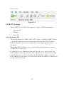
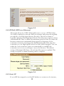
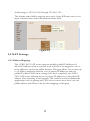
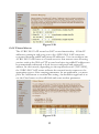
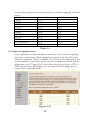
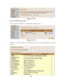
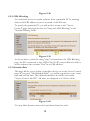
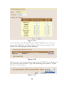
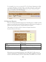
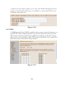
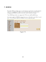
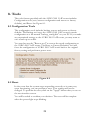
SOYO – AVRO 3001 ROUTER USER MANUAL
Table of Content
1. Introduction............................................................................. 1
1.1 Product Overview ....................................................................................... 1
2. Hardware Description......................................................... 2
2.1 Front Panel ................................................................................................... 2
2.2 Rear Panel ..................................................................................................... 3
3. Default Values ......................................................................... 4
3.1 Password ....................................................................................................... 4
3.2 Default Network Setup .............................................................................. 4
3.3 Other Default settings ................................................................................ 4
4. Login AVRO 3001 VoIP router ......................................... 5
5. Configure AVRO 3001 VoIP router ......................................... 7
5.1 System............................................................................................................ 7
5.1.1 Time Zone .......................................................................................................7
5.1.2 Password Settings.......................................................................................7
5.1.3 Remote Management......................................................................................8
5.2 WAN Settings .............................................................................................. 9
5.2.1 Dynamic IP...................................................................................................9
5.2.2 PPPoE (PPP over Ethernet)...................................................................10
5.2.3 Static IP ........................................................................................................10
5.2.4 DNS................................................................................................................11
5.3 LAN Settings............................................................................................. 11
5.4 NAT Settings............................................................................................. 12
5.4.1 Address Mapping ..........................................................................................12
5.4.2 Virtual Server ............................................................................................13
5.4.3 Special Applications ................................................................................14
5.5 Firewall ........................................................................................................ 15
5.5.1 Access Control ..............................................................................................15
5.5.2 URL Blocking..............................................................................................18
5.5.3 Schedule Rule ................................................................................................18
5.5.4 Intrusion Detection ......................................................................................20
5.5.5 DMZ ..............................................................................................................21
6. UPnP (Universal Plug and Play)........................................... 22
7. DDNS .................................................................................... 23
8. Tools ..................................................................................... 24
8.1 Configuration Tools.................................................................................. 24
8.2 Reset ............................................................................................................ 24
9. Status ..................................................................................... 26
9.1 Internet Connection.................................................................................. 26
9.2 Device Status.............................................................................................. 27
9.3 Security Log................................................................................................ 27
9.4 DHCP Client Log...................................................................................... 28
9.5 VoIP Status................................................................................................. 28
Glossary ..................................................................................... 30
Compliances.............................................................................. 37
1. Introduction
The AVRO 3001 VoIP router is a device that combines a Voice Gateway
and a Broadband Router in a single unit. The Broadband Router is designed
to share a single Internet access among two or more PCs in a household and
to provide Internet security for the PCs connected to its LAN ports. The
AVRO 3001 VoIP router also provides Voice over IP (VoIP) functionality
that enables you to make voice calls over the Internet. Please read this User
Manual for advanced features of this product.
1.1 Product Overview
The AVRO 3001 VoIP router is equipped with one standard analog
telephone port, one WAN Fast Ethernet 10/100BaseTX port and four LAN
Fast Ethernet 10/100BaseTX ports.
It also has the ability to route data between any PCs that are connected on
the LAN ports of the Gateway, up to a maximum of four PCs. The AVRO
3001VoIP router is H.323 v2 compliant for Voice over IP (VoIP) and it is
compatible with most High Speed Internet Service with built-in DHCP and
PPPoE client.
The services offered to the internal network are:
•
DHCP Server
•
Network Address Translation (NAT)
•
Network Address Port Translation (NAPT)
•
IPSEC pass through
The AVRO 3001 VoIP router has the ability to prioritize voice over data
through IP Layer QoS, Ethernet Layer CoS (Classes of Service) and VLAN
Tagging.
The AVRO 3001 VoIP router has 8 LEDs on the front panel that provides
status indication that can be used for troubleshooting purposes. See section
2.1
1
2. Hardware Description
2.1 Front Panel
The AVRO 3001 VoIP router includes an LED display on the front panel
for system power and port indications that simplifies installation and
network troubleshooting.
The following is the illustration and description of LED indicators:
POWER MODEM OK
LAN1 LAN2 LAN3 LAN4 PHONE
Figure 2-1
Function
Label
Power
POWER
WAN
MODEM
Internet
Link
OK
LAN
LAN1 to
LAN4
Phone
PHONE
Status
On
(Green)
Blink
Off
On
(Green)
Meaning
The AVRO 3001 VoIP router is
powered on
The VoIP Router is loading firmware
Power off or failure
WAN connection is functioning
correctly
The VoIP Router is
transmitting/receiving data
WAN connection is not established
Flashing
Off
On
(Orange)
Off
On
(Green)
Flashing
Off
On
(Orange)
Blink
(Ring)
Blink
(Alert)
Off
Internet connection is OK
No Internet connection
LAN connection is OK
The LAN port is sending/receiving data
No LAN port connection
The phone is off hook
Ring for incoming voice calls (follow the
ring pattern)
Gatekeeper register failed (one second
on, one second off)
The phone is on hook
2
2.2 Rear Panel
The rear panel contains the following items:
Figure 2-2
Item
Power
Reset
Modem
LAN 1 to 4
Phone
Description
Connect to the power adapter
Press this button for more than 5 seconds to reset and restore
the default factory settings
Connect your cable/DSL modem to this port with an Ethernet
Cable
Fast Ethernet port (RJ-45). Connect devices on your local area
network to this port (i.e., a PC, hub, or switch) with an
Ethernet Cable
Connect your telephone to this port
3
3. Default Values
3.1 Password
The default username is "user" and the default password is "user". Please
note that the username and password is case sensitive. For security and
management reasons, we recommend that you set up a new password after
you first login to the system. Once you have changed the password, it is
important that you write it down and keep this information in a safe
location. If you happen to forget the username and password, you can push
and hold the reset button for at least 5 seconds, or until all of the LEDs
flash.
Your AVRO 3001 VoIP router is now reset to the factory default settings.
By resetting the Gateway you will loose all changes you have made to date.
Any customization (i.e. your PPPoE username and password) will need to
be reentered.
3.2 Default Network Setup
LAN Setup
IP Address
192.168.1.1
Subnet Mask
255.255.255.0
DHCP Server
Enabled
DHCP IP Range
192.168.1.100 to 192.168.1.199
WAN Setup
DHCP Client
Enabled
Table 3-1
3.3 Other Default settings
Function
Settings
Time Zone
Firewall
Eastern Standard Time
Off
UPnP
Off
DDNS
Off
Table 3-2
4
4. Login AVRO 3001 VoIP router
Now that you have successfully connected the AVRO 3001 VoIP router
using the Quick Installation Guide and activated your Internet Phone
Service, you will need to login into the AVRO 3001 VoIP router to
configure it for your LAN.
1. Open your Web browser (i.e. Internet Explorer or Netscape Navigator).
2. In the Address field type in the following address: http://192.168.1.1,
and press Enter.
Figure 4-1
3. The AVRO 3001 VoIP router login screen will appear. The default
username is "user" and the default password is "user". For security
reasons, you should assign a new password as soon as possible. Please
note that the login username and password is case sensitive.
Figure 4-2
4. Once you have successfully logged in, the first page will appear as below:
5
Figure 4-3
6
5. Configure AVRO 3001 VoIP router
Please note that changing some settings on the AVRO 3001 VoIP router
may cause an interruption if attempted during a call.
5.1 System
5.1.1 Time Zone
Set the proper time zone and configure the time server for the AVRO 3001
VoIP router. The default time zone is Eastern Standard Time. When you
enable the Automatic Time Server Maintenance option you will need to
configure two time servers, see example provided below.
Figure 5-1
5.1.2 Password Settings
Set the password of the user. The Idle Time Out value is used for AVRO
3001 VoIP router to log out automatically when there has been no access to
the web after this timeout value. The default Idle Time Out value is 10
minutes.
7
Figure 5-2
5.1.3 Remote Management
The Remote Management feature can restrict the access to your AVRO
3001 VoIP router from the Internet. Unless you have a need to access
AVRO 3001 VoIP router from outside your home, this feature should be
disabled. You can enable it from a specific IP address or from any outside
IP address. The IP setting of "0.0.0.0" allows any person from any IP
address to login into the device. When the Enabled check box is not
checked, the remote login feature will be disabled. The default setting is that
Enable is not checked.
Figure 5-3
The remote user can login using WAN IP. The default port number is 8080.
For example, if your public IP address is 211.20.16.1, then you would type
the following string into your browser to remotely access your AVRO 3001
8
VoIP router.
Figure 5-4
5.2 WAN Settings
The AVRO 3001 VoIP router supports 3 types of WAN connection:
•
Dynamic IP
•
PPPoE
•
Static IP
5.2.1 Dynamic IP
This mode allows the AVRO 3001 VoIP router to enable its DHCP client
to get an IP address from your High Speed Service Provider. The Host
Name is optional, but may be required by some High Speed Service
Providers.
The default MAC address is set to the WAN’s physical interface on the
AVRO 3001 VoIP router.
If required by your High Speed Service Provider, you can use the Clone
MAC Address button to copy the MAC address of the Network Interface
Card installed in your PC and replace the WAN MAC address with this
MAC address. If necessary, you can restore the MAC address to the factory
setting. (See Section 8.1)
9
Figure 5-5
5.2.2 PPPoE (PPP over Ethernet)
This mode allows the AVRO 3001 VoIP router to act as a PPPoE client.
You will be required to enter the PPPoE username and password originally
provided by your High Speed Service Provider. The Service Name is
normally optional; some High Speed Service Providers may require it. Enter
a Maximum Idle Time to define the maximum period of time for which the
Internet connection is maintained during periods of inactivity. If the
connection is inactive for longer than the Maximum Idle Time, then the
connection to your High Speed Service Provider will be dropped. You can
enable the Auto-reconnect option to automatically re-establish the
connection as soon as you attempt to access the Internet. The default
setting is Maximum Idle Time of 0 and Auto Reconnect is enabled. This
setting is required to enable incoming calls to complete.
Figure 5-6
5.2.3 Static IP
If your ISP has assigned you a fixed IP address to connect to the internet,
10
enter the assigned IP address, subnet mask, and the gateway address here.
Figure 5-7
5.2.4 DNS
Most service providers provide a DNS server via DHCP or PPPoE for
speed and convenience. If you have a static IP address, or if there is a DNS
server that you would rather use, you need to specify the primary and
secondary IP address here. When the primary DNS does not work, the
system will automatically use the secondary DNS.
Figure 5-8
5.3 LAN Settings
You can enable DHCP to dynamically allocate IP addresses to each of your
PCs connected to the AVRO 3001 VoIP router. When DHCP server is
enabled, you need to enter the IP address range for the local hosts. The
11
default range is 192.168.1.100 through 192.168.1.199.
The domain name field is empty in most cases. Some ISPs may need you to
input a domain name within the Domain Name field.
Figure 5-9
5.4 NAT Settings
5.4.1 Address Mapping
The AVRO 3001 VoIP router supports multiple public IP addresses. It
allows IP addresses used in a private local network to be mapped to one or
more addresses used in the public Internet. This page allows you to enter up
to 10 address mappings between a set of private IP addresses and one
public IP address. After these settings have been completed, the AVRO
3001 VoIP router will map the set of private IP addresses to the public IP
address when accessing to the Internet. This could be useful in multimedia
applications such as gaming and VPN; however most users have only one
public address and will use only the first mapping on this page.
12
Figure 5-10
5.4.2 Virtual Server
The AVRO 3001 VoIP router has NAT router functionality. All the IP
addresses coming in and going out to the AVRO 3001 VoIP router are
converted between public and private IP addresses. You can configure the
AVRO 3001 VoIP router as a virtual server so that remote users accessing
services such as the Web or FTP at your local sites via public IP address can
be automatically redirected to local servers configured with private IP
address. In other words, depending on the requested service (TCP/UDP),
the AVRO 3001 VoIP router redirects the external service request to the
appropriate server. After entering parameters for an application, you must
press the Add button to confirm this setting. An alternative approach is to
use the Clear button to clear all fields and enter another parameter.
Figure 5-11
13
Some popular applications and protocol/port numbers mapping are listed
below:
Application
Protocol
Port Number
Telnet
TCP
23
FTP
TCP
21
SMTP
TCP
25
POP3
TCP
110
H.323
TCP
1720
SNMP
UDP
161
SNMP Trap
UDP
162
HTTP
TCP
80
PPTP
TCP
1723
PC Anywhere
TCP
5631
PC Anywhere
UDP
5632
Table 5-1
5.4.3 Special Applications
Some applications require multiple connections, such as Internet gaming
and video conferencing. These applications cannot work when Network
Address Translation (NAT) is enabled. If you need to run applications that
require multiple connections, specify the port normally associated with an
application in the "Trigger Port" field. Select the protocol type as TCP or
UDP and then enter the public ports associated with the trigger port to
open them for inbound traffic.
Figure 5-12
14
Some of the applications are listed below:
Trigger Port
28800
Trigger Type
UDP
6112
UDP
Public Port
2300-2400
47624,28800
6112
Public Type
UDP/TCP
UDP
Comment
MSN Game
zone
Battle.net
Table 5-2
5.5 Firewall
The AVRO 3001 VoIP router provides firewall protection by restricting
connection parameters to limit the risk of intrusion attempts, by defending
against a wide array of common intrusion types. When the firewall is
enabled, extra checking will be performed for each of the packets passing
through the AVRO 3001 VoIP router. However, this extra checking may
affect the performance of the device, so it should be used on an as-needed
basis. To enable the firewall feature, select Enable from this firewall page.
By default, Firewall is disabled.
Figure 5-13
5.5.1 Access Control
Access Control allows you to block specific PCs on your network from
gaining access to the Internet. You can block PCs based on either the IP
address or the MAC address. When the firewall is enabled, Access Control
will be enabled automatically. You can disable the filtering feature manually.
When Access Control is enabled, all packets will be allowed by default. You
can use the "Normal Filtering Table" and the "MAC Filtering Table" to
filter out disallowed traffic.
15
Figure 5-14
Normal Filtering Table
You can press Add PC to edit packet filtering rules.
Figure 5-15
When you click Add PC, the following "Access Control Add PC" page will
appear:
16
Figure 5-16
This page allows you to define service limitations of a specific PC, including
IP address, service type and scheduling rule criteria. For URL blocking
function, you will need to configure the URL address first in the "URL
Blocking Site" page. For scheduling function, you will also need to
configure schedule rule first in the "Schedule Rule" page.
You will need to enter the Client PC Description (e.g. NoteBook1), and it’s
associated IP address (192.168.1.100), then select the service name "WWW"
and "E-mail Sending", and then press OK. The following page will then be
displayed. In the example below, the PC with IP address 192.168.1.100 will
not be able to use WWW or send e-mail. The AVRO 3001 VoIP router
supports up to 32 filtering rules.
Figure 5-17
MAC Filtering Table
You can enter up to 32 MAC addresses. The PCs with these MAC
addresses will not be permitted to access the Internet.
17
Figure 5-18
5.5.2 URL Blocking
You can block access to certain websites from a particular PC by entering
either a full URL address or just a keyword of the Web site.
To specify the particular PC, you will need to return to the "Access
Control" page and check the box for "http with URL Blocking" in the
"Normal Filtering Table".
Figure 5-19
As shown above, when the string "chat" is entered into the URL Blocking
page, the PCs connected to the AVRO 3001 VoIP router will not be able to
access websites that contains "chat" in its URL address.
5.5.3 Schedule Rule
This page allows you to define a schedule rule for use in the Access Control
page. If you press "Add Schedule Rule", you will be required to enter a start
time and an End time. This defined schedule rule will be used under
"Access Control Add PC". All times are displayed as a 24 hour clock.
Figure 5-20
You may filter Internet access for local clients based on rules.
18
Figure 5-21
As shown above, for the schedule rule called "Office Hours", the active
time period is Monday to Friday, 9:00 to 17:00. After pressing the OK
button, the following page will be displayed.
Figure 5-22
When we go to the Access Control page, select "Add PC", in the bottom of
the "Access Control Add PC" page, the scheduling rule will show "Office
Hours", as shown below:
Figure 5-23
19
For example, if you were to setup the PC of the finance department within
a company (IP address 192.168.1.100 to 192.168.1.130) they would not be
able to access the Internet during office hours. In the "Access Control"
page, you would see the following page:
Figure 5-24
5.5.4 Intrusion Detection
When the SPI (Stateful Packet Inspection) firewall feature is enabled, specific
packets can be blocked. Stateful Packet Inspection (SPI) allows full support of
different attack types that are using dynamic port numbers.
This product’s firewall can block common attempted intrusions.
Intrusion Detection Features:
Figure 5-25
Item
Functions
SPI and Anti-DoS Firewall
Protection
RIP Defect
Discard PING from WAN
Activate SPI and Anti-DoS protection
Reject the RIP packets from WAN
Reject all the PING request to the WAN port
Table 5-3
When there is an attempted intrusion, the AVRO 3001 VoIP router can
send an e-mail alert to a specified person. You will be required to enter the
related e-mail information, such as e-mail address and SMTP server. Some
20
e-mail service providers require you to also enter POP3 information when
trying to send e-mail. In this case, you will have to enter the POP3 server,
username and password.
Figure 5-26
5.5.5 DMZ
A DeMilitarized Zone (DMZ) can allow direct access from the Internet to a
specific PC, while keeping other PCs protected within the home network.
This feature may be required if an application running on that PC requires
direct access to the Internet, and/or if the ports that need to be opened for
inbound requests that cannot be predicted.
Figure 5-27
21
6. UPnP (Universal Plug and Play)
The Universal Plug and Play architecture offers pervasive peer-to-peer
network connectivity of PCs of all types, intelligent appliances, and wireless
devices. UPnP enables seamless connectivity between the router and
various networked devices at home.
For example, if you want to use Windows XP Messenger application, this
feature should be enabled.
Figure 6-1
22
7. DDNS
Dynamic DNS provides users on the Internet a method to tie their domain
name to a temporary IP address automatically. This can be achieved by
changing the DDNS records every time your IP address changes.
Two DDNS providers are supported: TZO.com and DynDNS.org.
You must apply for DDNS service from one of the above providers to get a
Key. You can then enable the DDNS service using this page.
Figure 7-1
23
8. Tools
The tools feature provided with the AVRO 3001 VoIP router includes:
Configuration tools (save/restore configuration and restore to factory
defaults), and Reset. See Figure 8-1.
8.1 Configuration Tools
The configuration tools includes backup, restore and restore to factory
defaults. The Backup tool saves the AVRO 3001 VoIP router’s current
configuration to a file named "backup_config.bin" on your PC. If you made
any customized settings to the AVRO 3001 VoIP router, you may want to
save a back-up on a disk.
You can then use the "Restore tool" to restore the saved configuration to
the AVRO 3001 VoIP router. The Reset to Factory Defaults’s tool will
force the configuration of AVRO 3001 VoIP router back to the original
factory setting and perform a power reset.
Figure 8-1
8.2 Reset
In the event that the system stops responding correctly or in some way
stops functioning, you can perform a reset. Your settings will not be
changed. To perform the reset, click on the "Apply" button that you see on
the user interface screen.
You will be asked to confirm your decision. The reset will be complete
when the power light stops blinking.
24
Figure 8-2
25
9. Status
These status pages display the status of the system, including the connection
status of the interfaces, firmware and hardware versions, system log, and
DHCP client information. The Status and Information page below shows
MAC addresses and hardware/software versions.
Figure 9-1
9.1 Internet Connection
The Internet Connection page displays the status of the Internet
Connection, including the connection status of the Internet interfaces,
WAN port IP, Subnet Mask, Gateway IP and Primary/Secondary DNS IP.
Figure 9-2
26
When the WAN port setting is "dynamic IP", you can use "Release" and
"Renew" to release and update the WAN port IP address.
9.2 Device Status
The Device Status page displays the current setting of this device, including
IP address, Subnet mask, DHCP server, Firewall and UPnP.
Figure 9-3
9.3 Security Log
This page provides the system security log record when the AVRO 3001
VoIP router boots, including user login/logout, intrusion attempts, PPPoE
connection, NTP connection, Get IP from DHCP, etc.
These records can be saved to a host PC. You have the option to clear all
security records in Security log window and press the Refresh button to
update current security records.
27
Figure 9-4
9.4 DHCP Client Log
The DHCP Client Log page displays the IP addresses assigned to PCs in
your network. You can press the Refresh button to update current IP
allocation records.
Figure 9-5
9.5 VoIP Status
This page displays the VoIP gateway status, including port type, port Status,
time information of each call and Destination. This page also displays
gatekeeper status.
28
Figure 9-6
You can press the Refresh button to update the current VoIP status.
29
Glossary
10BASE-T
IEEE 802.3 specification for 10 Mbps Ethernet over two pairs of Category
3, 4, or 5 UTP cable
100BASE-TX
IEEE 802.3u specification for 100 Mbps Fast Ethernet over two pairs of
Category 5 UTP cable
Asymmetric Digital Subscriber Line (ADSL)
ADSL allows more data to be sent over existing copper telephone lines than
analog or ISDN technologies. ADSL supports data rates up to8 Mbps
downstream rate and up to 640 Kbps upstream
Bandwidth
The difference between the highest and lowest frequencies available for
network signals. Also synonymous with wire speed, the actual speed of the
data transmission along the cable
Demilitarized Zone (DMZ)
A term taken from the military term for a safety zone between battle lines,
this refers to an area within the firewall. Often this is a single machine with
access to the internal site and the outside network
Denial of Service (DoS)
Action(s) that prevent any part of an information system from functioning
in accordance with its intended purpose. Usually flooding a system to
prevent it from servicing normal and legitimate requests
Domain Name Server (DNS)
An Internet service that translates domain names into IP addresses. Every
time you use a domain name, a DNS service must translate the name into
the corresponding IP address.
Dynamic DNS (DDNS)
A method/service which allows a DNS name to be constantly synchronized
with a dynamic IP address.
Dynamic Host Configuration Protocol (DHCP)
30
DHCP is a protocol used to dynamically assign IP addresses to devices on a
network as requested. With dynamic addressing, a device is assigned the
next available IP address from the address pool every time it connects to
the network. DHCP client support is built into all Windows operating
systems, from Windows 95 on.
Dynamic IP
The term used to describe how IP address is dynamically assigned to
computers as and when needed. Unlike Static IP addresses, the IP address is
temporary, and it changes every time you connect to your ISP.
Dynamic Routing
Dynamic routing uses a routing protocol to exchange routing information
with neighbouring routers on the network. It calculates routing tables based
on a given metric, such as least number of hops or shortest path. It can
respond to changes in the status or traffic on the network, re-routing traffic
as required.
Ethernet
A network communication system developed and standardized by DEC,
Intel, and Xerox, using baseband transmission, CSMA/CD access, logical
bus topology, and coaxial cable. The successor IEEE 802.3 standard
provides for integration into the OSI model and extends the physical layer
and media with repeaters and implementations that operate on fiber, thin
coax, and twisted-pair cable.
File Transfer Protocol (FTP)
A protocol commonly used to transfer files across the Internet.
Filter
When using G.lite ADSL, a low-pass filter is required to remove data signals
from any line connected directly to a telephone.
Firewall
A firewall is designed to prevent unauthorized access to or from a private
network.
Firmware
System software stored in a device's memory that controls the device
FXS
31
Short for Foreign Exchange Station interface, which is used to connect to
the telephone set or PBX, it provides ringing back, dial signal to the
telephone devices.
Gatekeeper
The gatekeeper maintains a registry of devices in the multimedia network.
The devices register with the gatekeeper at startup and request admission to
a call from the gatekeeper. The gatekeeper is an H.323 entity on the LAN
that provides address translation, control access, and bandwidth
management to the LAN for H.323 terminals and gateways
G.lite
A standard that defines the more economical splitterless ADSL connection
that transmits data at up to 1.5 Mbps downstream and 512 Kbps upstream.
This ADSL option can be installed without an on-site visit by the service
provider
H.245
H.245 is an International Telecommunication Union (ITU-T) standard that
defines the control functions of the network multimedia communication,
such as the agreement of the mutual communication capability, the
establishment of the voice and video channel, etc.
H.323
H.323 is an International Telecommunication Union (ITU-T) standard that
describes packet-based video, audio, and data conferencing. H.323 is an
umbrella standard that describes the architecture of the conferencing
system and refers to a set of other standards (H.245, H.225.0, and Q.931)
to describe its actual protocol.
Internet Protocol Address (IP Address)
It is the numeric address of a computer on the Internet. An IP address is
written as a set of four numbers separated by periods (each number can
range from 0 to 255).
Internet Service Provider (ISP)
A company that provides access to the Internet. This may be your local
telephone or cable company, or a dedicated Internet service company.
32
Internet Protocol Security (IPSec)
A security protocol that provides authentication and encryption over the
internet. Security is provided at the network or packet processing layer of
network communication, rather than the application layer. IPsec supports
two encryption modes - transport and tunnel. Transport mode encrypts
only the data portion of each packet, but leaves the header untouched. The
more secure tunnel mode encrypts both the header and the data portion.
On the receiving side, an IPsec-compliant device decrypts each packet.
ITSP
Short for Internet Telephony Service Provider, which is a general term for
the organization which provides the Internet Telphony service to the
general public
Local Area Network (LAN)
A group of interconnected computer and support devices.
LED
Light emitting diode used for monitoring a device or network condition.
MAC Address
Media Access Control address; the unique physical address of each device's
network interface card
Media Access Control (MAC)
A portion of the networking protocol that governs access to the
transmission medium, facilitating the exchange of data between network
nodes
Modem
Modulator-demodulator, a device that allows computers to communicate
with each other over telephone lines or other delivery systems by changing
digital signals to telephone signals for transmission and then back to digital
signals. Modems come in different speeds: the higher the speed, the faster
the data is transmitted.
Network Address Translation (NAT)
A standard that enables a local-area network (LAN) to use one set of IP
addresses for external traffic and a second set of addresses for internal
traffic.
33
Network Address Port Translation (NAPT)
NAPT is a special case of NAT, where internal IP numbers are hidden
behind a single external addresses, allowing you to connect many local users
to the Internet with a single-user ISP account. With NAPT, an almost
arbitrary number of connections is multiplexed using TCP port information
NTP
Network Time Protocol. A standard for synchronizing your system clock
with the true time, defined as the average of many high-accuracy clocks
around the world
Password Authentication Protocol (PAP)
A basic form of authentication, in which a user’s name and password are
transmitted over a network and compared to a table of name-password pairs
PBX
Short for Private Branch eXchange, a private telephone network used within
an enterprise. Users of the PBX share a certain number of outside lines for
making telephone calls external to the PBX
Ping
A utility used to determine whether a specific IP address is accessible. It
works by sending a packet to the specified address and waiting for a reply
POP3
Post Office Protocol 3. A protocol that provides a simple, standardized way
for users to access mailboxes and download messages to their computers
POTS
Short for Plain Old Telephone Service, which refers to the standard
telephone service that most homes use. In contrast, telephone services based
on high-speed, digital communications lines, such as ISDN and FDDI, are
not POTS. The main distinctions between POTS and non-POTS services
are speed and bandwidth. POTS is generally restricted to about 52 Kbps
(52,000 bits per second).
Point-to-Point Protocol over Ethernet (PPPoE)
A protocol for connecting remote hosts to the Internet over an always-on
connection by simulating a dial-up connection
PSTN
34
The POTS network is also called the Public Switched Telephone Network
Quality of Service (QoS)
A network protocol used to specify a guaranteed throughput level. This
protocol is often used by ATM providers to guarantee their customers a
minimum end-to-end latency
Router
A device used to interconnect networks over local or wide areas and provide
traffic control and filtering functions
Routing
Routing forwards incoming IP packets using statically defined routes or a
dynamic routing protocol such as RIP 2
Routing Information Protocol (RIP)
A protocol that specifies how routers exchange routing table information
SMTP
Simple Mail Transfer Protocol, it’s the protocol that you use to send e-mail
via your ISP. It is used with both POP3 and IMAP4
Splitter
A hardware device used in G.dmt to split the data and voice traffic before
passing it on to the network and phone system
Static IP
An IP address which is the same every time you log on to the Internet.
SPI (Stateful Packet Inspection)
Also referred to as dynamic packet filtering. Stateful inspection is a firewall
architecture that works at the network layer. Stateful packet inspection tracks
each connection traversing all interfaces of the firewall and makes sure they
are valid.
Transmission Control Protocol/Internet Protocol (TCP/IP)
Protocol suite that includes TCP as the primary transport protocol, and IPas
the network layer protocol.
Uniform Resource Locator (URL)
35
The global address of documents and other resources on the World Wide
Web. The first part of the address indicates what protocol to use, and the
second part specifies the IP address or the domain name where the resource
is located.
Universal Plug and Play (UPnP)
Universal Plug and Play is an architecture for pervasive peer-to-peer network
connectivity of intelligent appliances, wireless devices, and PCs of all form
factors. It is designed to bring easy-to-use, flexible, standards-based
connectivity to ad-hoc or unmanaged networks whether in the home, in a
small business, public spaces, or attached to the Internet
Universal Plug and Play is a distributed, open networking architecture that
leverages TCP/IP and the Web technologies to enable seamless proximity
networking in addition to control and data transfer among networked
devices in the home, office, and public spaces.
Virtual Host
A network device, such as this router, or a server configured to perform
Network Address Translation (NAT).
Virtual Server
Transparently redirects specific service requests (such as Web or FTP) to a
dedicated local server.
Voice over Internet Protocol (VoIP)
Another way of saying IP Telephony. It involves the transmission of
telephone calls over a data network like the Internet. In other words, VoIP
can send voice, fax and other information over the Internet, rather than
through the (PSTN) or regular telephone network.
36
Compliances
Industry Canada - Class B
This digital apparatus does not exceed the Class B limits for radio noise
emissions from digital apparatus as set out in the interference-causing
equipment standard entitled "Digital Apparatus," ICES-003 of the
Department of Communications.
Cet appareil numerique respecte les limites de bruits radioelectriques
applicables aux appareils numeriques de Classe B prescrites dans la norme
sur le materiel brouilleur: "Appareils Numeriques," NMB-003 edictee par
le ministere des Communications
Federal Communication Commission Interference
Statement
This equipment has been tested and found to comply with the limits for a Class B
digital device, pursuant to Part 15 of the FCC Rules. These limits are designed to
provide reasonable protection against harmful interference in a residential installation.
This equipment generates uses and can radiate radio frequency energy and, if not
installed and used in accordance with instructions, may cause harmful interference to
radio communications. However, there is no guarantee that the interference will not
occur in a particular installation. If this equipment does cause harmful interference to
radio or television reception, which can be determined by turning the equipment off
and on, the user is encouraged to try to correct the interference by one or more of the
following measures:
•
•
•
Reorient or relocate the receiving antenna
Increase the separation between the equipment and receiver
Connect the equipment into an outlet on a circuit different from that to which the
receiver is connected
• Consult the dealer or an experienced radio/TV technician for help
FCC Caution: To assure continued compliance, (example - use only
shielded interface cables when connecting to computer or peripheral devices)
any changes or modifications not expressly approved by the party
responsible for compliance could void the user’s authority to operate this
equipment.
37