1
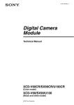
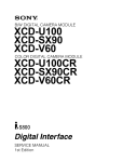
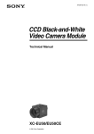
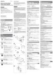
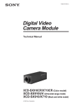
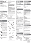
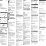
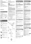
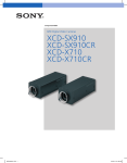
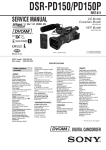
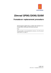
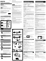
3-287-508-01 (1) Owner’s Record 日本語 English A The model and serial numbers are located on the bottom. Record the serial number in the space provided below. Refer to these numbers whenever you call upon your Sony dealer regarding this product. Digital Camera Module When Installing the Camera Fig. A When you install the camera with various peripheral devices and if the devices have different ground electric potential, ground only one device. In case there is an ground electric potential difference, the camera may be damaged. Model No. _____________ Serial No. ______________ -1 Basic configuration / -2 Optional configuration -1 基本構成/ -2 オプションの構成 WARNING To reduce the risk of fire or electric shock, do not expose this apparatus to rain or moisture. Operating Instructions お買い上げいただきありがとうございます。 To avoid electrical shock, do not open the cabinet. Refer servicing to qualified personnel only. IEEE1394b PC 12 IEEE1394b connector Host device (e.g., PC) Ground electric potencial difference I/O DC-700 Notes on Operation Power supply 電源について PC Power is supplied to the camera module via the IEEE1394b cable connected to a PC. If the power supply is insufficient, use the DC-700/700CE that supplies stable power with less ripple or noise. IEEE1394b Foreign bodies DC-700 XCD-V60CR/SX90CR/U100CR (Color model) XCD-V60/SX90/U100 (Black and white model) 2007 Sony Corporation Printed in Japan 3287508010 IMPORTANT The nameplate is located on the bottom. 使用・保管場所 Power Supply The unit must always be operated with a 12V DC class 2 power supply. In the USA, use a power supply which is UL Listed. For the customers in the U.S.A. This equipment has been tested and found to comply with the limits for a Class A digital device, pursuant to Part 15 of the FCC Rules. These limits are designed to provide reasonable protection against harmful interference when the equipment is operated in a commercial environment. This equipment generates, uses, and can radiate radio frequency energy and, if not installed and used in accordance with the instruction manual, may cause harmful interference to radio communications. Operation of this equipment in a residential area is likely to cause harmful interference in which case the user will be required to correct the interference at his own expense. You are cautioned that any changes or modifications not expressly approved in this manual could void your authority to operate this equipment. All interface cables used to connect peripherals must be shielded in order to comply with the limits for a digital device pursuant to Subpart B of Part 15 of FCC Rules. 安全のための注意事項を守る。 故障したり破損したら使わずに、ソニーのサービス窓口に相談する。 警告表示の意味 注意を促す記号 行為を禁止する記号 For customers in Europe This camera is not intended for use in security applications in the meaning of the European standard series EN 50132 (Alarm systems CCTV surveillance systems for use in security applications). For the customers in Europe The manufacturer of this product is Sony Corporation, 1-7-1 Konan, Minato-ku, Tokyo, Japan. The Authorized Representative for EMC and product safety is Sony Deutschland GmbH, Hedelfinger Strasse 61, 70327 Stuttgart, Germany. For any service or guarantee matters please refer to the addresses given in separate service or guarantee documents. Be careful not to spill liquids, or drop any flammable or metal objects in the camera body. Avoid operation or storage in the following places. E xtremely hot or cold locations. Recommended temperature range is 0°C to 40°C (32°F to 104°F) Locations subject to strong vibration or shock Near generators of strong electromagnetic radiation such as TV or radio transmitters お手入れ Care Use a blower to remove dust from the surface of the lens or optical filter. Clean the exterior with a soft, dry cloth. If the camera is very grimy, apply a cloth soaked in a mild detergent then wipe with a dry cloth. Do not apply organic solvents such as alcohol which may damage the finish. Overview XCD-V60CR/SX90CR/U100CR RAW XCD-V60/SX90/U100 IEEE1394b端子 800Mbps IEEE1394b The XCD-V60CR/SX90CR/U100CR is a color digital camera module that outputs RGB Raw Data. The XCD-V60/SX90/U100 is a monochrome digital camera module. 2 IEEE1394b connector 高画質 The camera module can output a digital image with a transfer speed of 800 Mbps. Two IEEE1394b connectors allow you to make up a daisy chain connection. CCD XCD-V60CR/V60 30 200 CCD UXGA VGA 33 CCD 90 XCD-SX90CR/SX90 SXGA 125 CCD XCD-U100CR/U100 CCD 15 外部トリガー機能 Electronic shutter You can select the exposure time from a variety of settings. This allows you to capture an image under optimal conditions. 12 12 I/O 12-pin I/O connector When power from the IEEE1394b connector is insufficient, power is supplied through the 12-pin connector. The 12-pin connector is also used for a trigger input and strobe output, and as a general-purpose I/O port. 低消費電力 XCD-V60CR/V60/SX90CR/SX90 XCD-U100CR/U100 3.0W DC 12V 2.8W DC 12V Low power consumption The power consumption is decreased to 2.8 W for the XCD-V60CR/V60/SX90CR/ SX90 or 3.0 W for the XCD-U100CR/U100, with 12 V DC input. CCD により があります。 や や Body fixing The mounting screw holes are provided in the reference plane on the lower surface of the body, allowing mounting with the absolute minimum deviation of the optical axis. CCD 、 につながること CCD –1 Charge Coupled Device 白点 CCD / Camera 設置は確実に The following phenomena that may appear in images are specific to CCD (Charge Coupled Device) image sensors. They do not indicate malfunctions. Although the CCD image sensors are produced with high-precision technologies, fine white flecks may be generated on the screen in rare cases, caused by cosmic rays, etc. This is related to the principle of CCD image sensors and is not a malfunction. The white flecks especially tend to be seen in the following cases: when operating at a high environmental temperature when you have raised the gain (sensitivity) when using the slow shutter スミア現象 Vertical smear When an extremely bright object, such as a strong spotlight or flashlight, is being shot, vertical tails may be produced on the screen, or the image may be distorted. –2 / Camera レンズは確実に取り付ける Phenomena Specific to CCD Image Sensors White flecks CCD 1 The camera module uses a progressive scan CCD and produces high-resolution and high-speed image output. The XCD-V60CR/V60 has a CCD of 330,000 pixels (VGA) and outputs a digital image at 90 frames per second. The XCD-SX90CR/SX90 has a CCD of 1,250,000 pixels (SXGA) and outputs at 30 frames per second. The XCD-U100CR/U100 has a CCD of 2,000,000 pixels (UXGA) and outputs at 15 frames per second. Because the CCDs are square pixel CCDs, you don’t need to convert the aspect ratio in your image processing. You can operate the shutter at any timing by synchronizing the shutter with the external trigger signals. 電子シャッター 筐体固定 下記の注意を守らないと、 High resolution External trigger function IEEE1394b 行為を指示する記号 Locations for operation and storage 0 40 12ピンI/Oコネクター端子 This apparatus shall not be used in the residential area. 12-pin I/O connector Abnormal electricity Power supply unit (DC-700/700CE) Monitor screen Bright object (e.g. strong spotlight, strong reflected light, flashlight, the sun) 折り返しひずみ 1 B 下記の注意事項を守らないと、 を与えることがあります。 をしたり周辺の物品に ) ( CCD IEEE1394bカメラケーブル(市販) IEEE1394b DC Cマウントレンズ(市販) カメラ用画像入力ボード(市販) 分解しない、改造しない PC 800Mbps PCI IEEE1394 IEEE1394b 三脚アダプター VCT-ST70I(ソニー製) カメラケーブルを傷つけない カメラアダプター DC-700(ソニー製) AC カメラケーブルCCXC-12P02N(2 m)/05N(5 m)/10N(10 m) (ソニー製) /25N(25 m) 12 I/O C レンズマウント(Cマウント) System Components Fig. B Camera module This is a small-size, high-resolution, camera module using a CCD image sensor. IEEE1394b camera cable (commercially available) Connect this cable to the IEEE1394b connector on the rear panel of the camera module. The power and image/control signals are transmitted through this cable. To prevent a poor connection or damage to the camera or cable, use the cable equipped with fixing screws. C-mount lens (commercially available) Use an appropriate lens for the camera module and usage. Camera module interface board (commercially available) Install the board in a PCI bus slot of a host device such as a PC. Select an IEEE1394 interface board to match your system. Select an IEEE1394b interface board if you use the transfer speed of 800 Mbps. VCT-ST70I tripod adaptor (Sony) Attach this adaptor to the bottom of the camera module to fix the camera module to a tripod. DC-700/700CE camera adaptor (Sony) Connect this adaptor to the camera module to enable power supply from an ordinary AC power source. CCXC-12P02N (2 m, 6.6 ft)/05N (5 m, 16.4 ft)/10N (10 m, 32.8 ft)/ 25N (25 m, 82 ft) camera cable (Sony) Connect this cable to the 12-pin I/O connector on the rear panel of the camera module. The cable is used for power supply and exchange of trigger signals. ご注意 Note C 10mm Fig. C Front/Top/Bottom Lens mount (C-mount) Attach any C-mount lens or other optical equipment. C 10mm The lens must not project more than 10 mm (13/32 inch) from the lens mount. Lens mount face 10 mm (13/32 inch) or less Auxiliary holes (top) カメラ固定用補助穴(上面) 指定された接続ケーブルを使う When fine patterns, stripes, or lines are shot, they may appear jagged or flicker. Location and Function of Parts and Operation 指定された専用機器に接続する Aliasing The camera module imaging system comprises the following products. Products to are used for the basic configuration, and to for the optional configuration. (All the products except the camera module are available separately.) カメラモジュール 内部に水や異物を入れない Vertical tails shown on the image Reference holes (bottom) These precision screw holes are for locking the camera module. Locking the camera module into these holes secures the optical axis alignment. カメラ固定用基準穴(底面) For details, refer to the Technical Manual. 4 ST70I 4 VCT- Four screw reference holes can be used as the tripod adapor screw holes, too. Screw the VCT-ST70I tripod adaptor into the four screw holes when you use a tripod. (continued on the reverse side) G IEEE1394b IEEE1394b 重要 XCD-V60CR/SX90CR/U100CR (color models) only Control function 1394b IEEE1394b VCCI A IEEE1394b 定期交換部品について 12 I/O CCXC-12P05N AC CAMERA AC IN English Rear Fig. D IEEE1394b connectors Connect an IEEE1394b camera cable (not supplied) to this connector. Pin No. 全モデル共通機能 制御項目 内容 0 0 1 /100,000 +18 dB +24 dB 1024 10 IIDC / Mode0( Signal Pin No. Signal 1 TPB– 6 VG 2 TPB+ 7 NC 3 TPA– 8 VP 4 TPA+ 9 TPBG 5 TPAG 12-pin I/O connector When power from the IEEE1394b connector is insufficient, power is supplied through this connector. Connect a camera cable such as the CCXC-12P05N to this connector. 16 Pin No. ) Mode1( ) Signal Pin No. Signal 1 Power GND 7 GPIO IN 2 2 Power IN 8 GPIO OUT 2- 3 ISO GND 9 GPIO OUT 2+ 4 Strobe OUT 10 GPIO IN 1 5 GPIO OUT 1- 11 Trigger IN 6 GPIO OUT 1+ 12 ISO GND Installation 1 Remove the lens mount cap. 2 Screw in the lens (not supplied), and turn it until it is secured. GPIO 12 ISO Enable( ) OneShot/MultiShot DataDepth CameraInitialize GPIO Note Clean the optical filter with a commercially available blower brush to remove dust. OneShot MultiShot 16 1 To use the tripod, install the VCT-ST70I tripod adaptor (not supplied) on the camera module. Use a tripod screw with a protrusion () extending from the installation surface, as follows: ISO standard: Length 4.5 mm to 5.0 mm ASA standard: Length 0.197 inches ) 1 ch/15 ch Tighten the tripod screws using a hand screwdriver. When you install the tripod adaptor, use the screws supplied with the tripod adaptor. Connecting the camera cable x 24 G 日本語 D IEEE1394b端子 IEEE1394b ピン番号 1 2 3 4 5 信号 ピン番号 TPB TPB TPA TPA TPAG 3x3 3x3 IEEE1394 信号 6 7 8 9 VG NC VP TPBG IEEE1394b CCXC-12P05N ピン番号 1 2 3 4 5 6 信号 ( ISO( ピン番号 ) ) GPIO GPIO 信号 7 8 9 10 11 12 1 1 GPIO GPIO GPIO GPIO ISO( 2 2 2 1 ( ) E 1 2 ご注意 F ISO ASA ご注意 4.5mm 0.197 5.0mm IMPORTANT The nameplate is located on the bottom. Note Always verify that the unit is operating properly before use. SONY WILL NOT BE LIABLE FOR DAMAGES OF ANY KIND INCLUDING, BUT NOT LIMITED TO, COMPENSATION OR REIMBURSEMENT ON ACCOUNT OF THE LOSS OF PRESENT OR PROSPECTIVE PROFITS DUE TO FAILURE OF THIS UNIT, EITHER DURING THE WARRANTY PERIOD OR AFTER EXPIRATION OF THE WARRANTY, OR FOR ANY OTHER REASON WHATSOEVER. Regular parts replacement Some of the parts that make up this product (electrolytic condenser, for example) need replacing regularly depending on their life expectancies. The lives of parts differ according to the environment or condition in which this product is used and the length of time it is used, so we recommend regular checks. Consult the dealer from whom you bought it for details. DC 5 24V C 17.526 mm XCD-V60CR/SX90CR/U100CR: 20 lx (F1.4 Gain: +18 dB) XCD-V60/SX90/U100: 2 lx (F1.4 Gain: +24 dB) = 1 LUT XCD-V60CR/SX90CR/U100CR: 0 +18 dB 16 Fig. H +24 dB 12 DC +8 V XCD-U100CR/U100: 3.0 W DC 12V 0 +40 5 45 30 60 20 80 ( ) 20 95 ( ) 10G (20Hz 200Hz 70G 44 (W) 33 (H) 57.5 (D)mm 140g (1) (1) 12-pin I/O connector Camera cable (e.g. CCXC-12P05N) to AC power source CAMERA connector AC IN connector Trigger generator You can control the camera from your PC. The following table shows the control functions. +30 V XCD-V60CR/V60/SX90CR/SX90: 2.8 W DC 12V Design and specifications are subject to change without notice. Controlling the Camera from Your PC IEEE1394b – 2002 ( ) XCD-V60CR/V60: 640 x 480 (VGA) XCD-SX90CR/SX90: 1,280 x 960 (SXGA) XCD-U100CR/U100: 1,600 x 1,200 (UXGA) XCD-V60CR/V60: 90 fps XCD-SX90CR/SX90: 30 fps XCD-U100CR/U100: 15 fps 800/400 Mbps ) 10 s 1/100,000 IEEE1394b Pickup device Progressive scan IT CCD XCD-V60CR/V60/SX90CR/SX90: 1/3 type XCD-U100CR/U100: 1/1.8 type Interface IEEE1394b – 2002 Output signal format (horizontal/vertical) XCD-V60CR/V60: 640 x 480 (VGA) XCD-SX90CR/SX90: 1,280 x 960 (SXGA) XCD-U100CR/U100: 1,600 x 1,200 (UXGA) Frame rate XCD-V60CR/V60: 90 fps XCD-SX90CR/SX90: 30 fps XCD-U100CR/U100: 15 fps Transfer speed 800/400 Mbps External trigger signal (conditions) Pulse width: 10 μs or more Polarity: Negative Amplitude: 5 to 24 V DC Lens mount C-mount Flange back 17.526 mm Minimum illumination XCD-V60CR/SX90CR/U100CR: 20 lx (F1.4, Gain: +18 dB) XCD-V60/SX90/U100: 2 lx (F1.4, Gain: +24 dB) Gamma γ= 1 (selectable by LUT) Gain XCD-V60CR/SX90CR/U100CR: 0 to +18 dB, Auto gain XCD-V60/SX90/U100: 0 to +24 dB, Auto gain Shutter speed 1/100,000~16 seconds, Auto shutter Power +8 V to +30 V DC from IEEE1394b camera cable or camera cable with 12-pin connector Power consumption XCD-V60CR/V60/SX90CR/SX90: 2.8 W (12 V DC input) XCD-U100CR/U100: 3.0 W (12 V DC input) Performance guaranty temperature 0 to +40°C (32 to 104°F) Operating temperature –5 to +45°C (23 to 113°F) Storage temperature –30 to +60°C (–22 to 140°F) Operating relative humidity 20 to 80% (no condensation) Storage relative humidity 20 to 95% (no condensation) Vibration resistance 10 G (20 Hz to 200 Hz, at using the reference holes) Shock resistance 70 G External dimension (w/h/d) 44 × 33 × 57.5 mm (13/4 × 13/16 × 23/8 inches), not including projecting parts Mass 140 g (4 oz) Accessories Lens mount cap (1) Operating Instructions (1) Power can be supplied to the camera module via the DC-700/700CE camera adaptor (optional) and a camera cable such as CCXC-12P05N (optional) if power supply from the IEEE1394b connector is insufficient. Ver.1.31 XCD-V60/SX90/U100: 0 VCT-ST70I When power supply from the IEEE1394b connector is insufficient IT CCD XCD-V60CR/V60/SX90CR/SX90: 1/3 XCD-U100CR/U100: 1/1.8 12ピンI/Oコネクター端子 Adjusting the image contour strength Loose fixing screws may cause a poor connection or damage to the camera or cable. Be sure to tighten the fixing screws. XCD-V60/SX90/U100(白黒モデル)のみ 内容 Switching the 3 x 3 filter Sharpness Note / G 制御項目 Description 3 x 3 Filter IEEE1394b connector Fixing screws IEEE1394b camera cable (not supplied) 内容 Raw R B Fig. G Connect a commercially available IEEE1394b camera cable to the IEEE1394b connector and the 1394b interface connector of your PC. When you connect the cable, insert the cable connector into the IEEE1394b connector until it snaps into place, holding it. Then, tighten the fixing screws placed on both sides of the cable connector. XCD-V60CR/SX90CR/U100CR(カラーモデル)のみ 制御項目 Control function Note 1394 32 256 Fig. F Using a tripod PresetMemory0( 1394 Fig. E Fitting the lens Switching the Bayer pattern Specifications DC- CCXC-12P05N Adjusting the G gain OpticalFilter These control items comply with Digital Camera Protocol, Ver. 1.31, of the IEEE1394 Standard. For more details, refer to the Technical Manual. H IEEE1394b 700( ) G Gain XCD-V60/SX90/U100 (black and white models) only ご注意 IEEE1394b Description WhiteBalance (Raw Adjusting the R and B levels individually mode) Auto white balance, One Push white balance available ) Functions common to all models Control function Description Gain Color model 0 to +18 dB Black and white 0 to +24 dB model Shutter Setting the shutter speed between 1/100,000 and 16 sec. Brightness Pedestal level adjustable Gamma Customizing the gamma curve using 1,024 gamma tables (10 bits) (IIDC extended function) Trigger Mode 0 (control by register) and Mode 1 (control by pulse width) supported for hardware trigger/software trigger Broadcast commands supported for software trigger Strobe Out Setting the delay from the exposure start and the pulse width by register value AutoExposure Keeping a constant average image level by the image level detection and feedback to gain and shutter AutoExposure Detection Frame Setting Setting the detection area for Auto Exposure GPIO Assigning GPIO (General-Purpose Input/Output) to the 12-pin connector MemoryShot Saving an image to the built-in frame memory and reading the saved image from the memory ISO Enable (Video Start) Starts transmitting an image in continuous mode OneShot/ MultiShot OneShot Transmitting an image MultiShot Transmitting the specified number of images DataDepth Indicating the effective bit length in 16-bit mode CameraInitialize Resetting the camera to the default features MemoryChannel PresetMemory0 (factory default status) and 1 user available memory channel / 15 user available memory channels selectable 1394 Bus Synchronization Defining the exposure timing in synchronization with the cycle time register of 1394 bus The Operating Instructions describe the functions and use of this product. TriggerDelay Specifying the delay time after which the received trigger becomes effective For more details, see the Technical Manual. Please ask your sales representative about the Technical Manual. PartialScan Partition by a unit of 32 lines x 24 pixels available UserFreeMemory A 256-byte user available memory provided Bulk Mode Acquiring images continuously by changing the settings in memory channels About the Technical Manual