1
4-128-127-12 (2)
Data
Projector
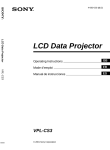
Operating Instructions
Before operating the unit, please read this manual thoroughly
and retain it for future reference.
VPL-DX10/DX11/DX15
Not all models are available in all countries and area. Please check
with your local Sony Authorized Dealer.
© 2009 Sony Corporation
WARNING
To reduce the risk of fire or electric
shock, do not expose this apparatus
to rain or moisture.
To avoid electrical shock, do not open
the cabinet. Refer servicing to
qualified personnel only.
WARNING
THIS APPARATUS MUST BE
EARTHED.
WARNING
When installing the unit, incorporate a
readily accessible disconnect device in the
fixed wiring, or connect the power plug to an
easily accessible socket-outlet near the unit.
If a fault should occur during operation of
the unit, operate the disconnect device to
switch the power supply off, or disconnect
the power plug.
Notice for customers
The statements for each country/area are
only applicable to equipment sold in that
country/area.
WARNING: THIS WARNING IS
APPLICABLE FOR USA ONLY.
If used in USA, use the UL LISTED power
cord specified below.
DO NOT USE ANY OTHER POWER
CORD.
Plug Cap Parallel blade with ground pin
(NEMA 5-15P Configuration)
Cord
Type SVT, three 18 AWG wires
Length
Minimum 1.5 m (4 ft .11in.),
Less than 2.4 m (7 ft .9 in.)
Rating
Minimum 7 A, 125 V
Using this unit at a voltage other than 120V
may require the use of a different line cord or
attachment plug, or both.
To reduce the risk of fire or electric shock,
refer servicing to qualified service
personnel.
2
WARNING
WARNING: THIS WARNING IS
APPLICABLE FOR OTHER
COUNTRIES.
1 Use the approved Power Cord (3-core
mains lead) / Appliance Connector / Plug
with earthing-contacts that conforms to
the safety regulations of each country if
applicable.
2 Use the Power Cord (3-core mains lead) /
Appliance Connector / Plug conforming
to the proper ratings (Voltage, Ampere).
If you have questions on the use of the above
Power Cord / Appliance Connector / Plug,
please consult a qualified service personnel.
IMPORTANT
The nameplate is located on the bottom.
For kundene i Norge
Dette utstyret kan kobles til et ITstrømfordelingssystem.
For the customers in the U.S.A.
This equipment has been tested and found to
comply with the limits for a Class B digital
device, pursuant to Part 15 of the FCC Rules.
These limits are designed to provide
reasonable protection against harmful
interference in a residential installation. This
equipment generates, uses, and can radiate
radio frequency energy and, if not installed
and used in accordance with the instructions,
may cause harmful interference to radio
communications. However, there is no
guarantee that interference will not occur in
a particular installation. If this equipment
does cause harmful interference to radio or
television reception, which can be
determined by turning the equipment off and
on, the user is encouraged to try to correct
the interference by one or more of the
following measures:
-Reorient or relocate the receiving antenna.
-Increase the separation between the
equipment and receiver.
-Connect the equipment into an outlet on a
circuit different from that to which the
receiver is connected.
-Consult the dealer or an experienced radio/
TV technician for help.
You are cautioned that any changes or
modifications not expressly approved in this
manual could void your authority to operate
this equipment.
Stuttgart, Germany. For any service or
guarantee matters please refer to the
addresses given in separate service or
guarantee documents.
All interface cables used to connect
peripherals must be shielded in order to
comply with the limits for a digital device
pursuant to Subpart B of Part 15 of FCC
Rules.
For the State of California, USA only
Perchlorate Material - special handling may
apply, See
www.dtsc. ca.gov/hazardouswaste/
perchlorate
Perchlorate Material: Lithium battery
contains perchlorate.
This device complies with Part 15 of the
FCC Rules. Operation is subject to the
following two conditions: (1) this device
may not cause harmful interference, and (2)
this device must accept any interference
received, including interference that may
cause undesired operation.
If you have any questions about this product,
you may call;
Sony Customer Information Service Center
1-800-222-7669 or http://www.sony.com/
Disposal of the used lamp
For the customers in the USA
Lamp in this product contains mercury.
Disposal of these materials may be regulated
due to environmental considerations. For
disposal or recycling information, please
contact your local authorities or the
Electronic Industries Alliance
(www.eiae.org).
For the customers in Taiwan only
Declaration of Conformity
Trade Name: SONY
Model:
VPL-DX10
VPL-DX11
VPL-DX15
Responsible party:
Sony Electronics Inc.
Address:
16530 Via Esprillo, San
Diego, CA 92127U.S.A.
Telephone Number:
858-942-2230
This device complies with part 15 of the
FCC Rules. Operation is subject to the
following two conditions: (1) this device
may not cause harmful interference, and
(2) this device must accept any interference
received, including interference that may
cause undesired operation.
For the customers in Canada
This Class B digital apparatus complies with
Canadian ICES-003.
For the customers in Europe
The manufacturer of this product is Sony
Corporation, 1-7-1 Konan, Minato-ku,
Tokyo, Japan.
The Authorized Representative for EMC
and product safety is Sony Deutschland
GmbH, Hedelfinger Strasse 61, 70327
WARNING
3
For VPL-DX15 only
For the customers in the U.S. A. and
Canada
This device complies with Part 15 of FCC
Rules and RSS-Gen of IC Rules. Operation
is subject to the following two conditions:
(1) this device may not cause interference,
and (2) this device must accept any
interference, including interference that may
cause undesired operation of this device.
This equipment complies with FCC/IC
radiation exposure limits set forth for
uncontrolled equipment and meets the FCC
radio frequency (RF) Exposure Guidelines
in Supplement C to OET65 and RSS-102 of
the IC radio frequency (RF) Exposure rules.
This equipment should be installed and
operated with at least 20cm and more
between the radiator and person’s body
(excluding extremities: hands, wrists, feet
and ankles).
For the customers in the U.S.A.
In according with 47 CFR Part15.407 (e) UNII devices operating in 5.15-5.25GHz
frequency bands are restricted to indoor
operations only.
This transmitter must not be co-located or
operated in conjunction with any other
antenna or transmitter.
For the customers in Europe
Notice for customers: the following information is only applicable to equipment sold in
Countries applying EU directives.
This product is intended to be used in the following countries:
AT BE BG CY CZ DK EE FI FR DE GR
HU IE IT LV LT LU MT NL PL PT RO
SK SI ES SE GB IS LI NO CH
4
Bulgarian
С настоящето Сони Корпорация декларира, че този VPL-DX15/Data
Projector отговаря на основните изисквания и другите сьответстващи
клаузи на Директива 1999/5/EC. Подробности може да намерите на
Интернет страницата : http://www.compliance.sony.de/.
Czech
Sony Corporation tímto prohlašuje, že tento VPL-DX15/Data Projector
je ve shodě se základními požadavky a dalšími příslušnými ustanoveními
směrnice 1999/5/ES. Podrobnosti lze získat na následující URL:
http://www.compliance.sony.de/
Danish
Undertegnede Sony Corporation erklærer herved, at følgende udstyr VPLDX15/Data Projector overholder de væsentlige krav og øvrige relevante krav i
direktiv 1999/5/EF. For yderligere information gå ind på følgende hjemmeside:
http://www.compliance.sony.de/
Dutch
Hierbij verklaart Sony Corporation dat het toestel VPL-DX15/Data Projector in
overeenstemming is met de essentiële eisen en de andere relevante bepalingen
van richtlijn 1999/5/EG. Nadere informatie kunt u vinden op: http://
www.compliance.sony.de/
English
Hereby, Sony Corporation, declares that this VPL-DX15/Data Projector is in
compliance with the essential requirements and other relevant provisions of
Directive 1999/5/EC. For details, please access the following URL: http://
www.compliance.sony.de/
WARNING
Estonian
Sony Corporation kinnitab käesolevaga seadme VPL-DX15/Data Projector
vastavust 1999/5/EÜ direktiivi põhinõuetele ja nimetatud direktiivist
tulenevatele teistele asjakohastele sätetele. Üksikasjalikum info: http://
www.compliance.sony.de/.
Finnish
Sony Corporation vakuuttaa täten että VPL-DX15/Data Projector tyyppinen
laite on direktiivin 1999/5/EY oleellisten vaatimusten ja sitä koskevien
direktiivin muiden ehtojen mukainen. Halutessasi lisätietoja, käy osoitteessa:
http://www.compliance.sony.de/
French
Par la présente Sony Corporation déclare que l’appareil VPL-DX15/Data
Projector est conforme aux exigences essentielles et aux autres dispositions
pertinentes de la directive 1999/5/CE. Pour toute information complémentaire,
veuillez consulter l’URL suivante: http://www.compliance.sony.de/
German
Hiermit erklärt Sony Corporation, dass sich das Gerät VPL-DX15/Data
Projector in Übereinstimmung mit den grundlegenden Anforderungen und den
übrigen einschlägigen Bestimmungen der Richtlinie 1999/5/EG befindet.
Weitere Informationen erhältlich unter: http://www.compliance.sony.de/
Greek
Με την
Projector
η Sony Corporation δηλώνει τι VPL-DX15/Data
και τις λ
της
1999/5/EK. Για
http://www.compliance.sony.de/
Hungarian
Alulírott, Sony Corporation nyilatkozom, hogy a(z) VPL-DX15/Data
Projector megfelel a vonatkozó alapvető követelményeknek és az
1999/5/EC irányelv egyéb előírásainak. További információkat a
következő weboldalon találhat: http://www.compliance.sony.de/
Italian
Con la presente Sony Corporation dichiara che questo VPL-DX15/Data
Projector è conforme ai requisiti essenziali ed alle altre disposizioni pertinenti
stabilite dalla direttiva 1999/5/CE. Per ulteriori dettagli, si prega di consultare il
seguente URL: http://www.compliance.sony.de/
Latvian
Lithuanian
Norwegian
Sony Corporation erklærer herved at utstyretVPL-DX15/Data Projector er i
samsvar med de grunnleggende krav og øvrige relevante krav i direktiv 1999/5/
EF. For flere detaljer, vennligst se: http://www.compliance.sony.de/
Polish
` VPL-DX15/Data Projector
Niniejszym Sony Corporation oświadcza, ze
jest zgodne z zasadniczymi wymaganiami oraz innymi stosownymi
postanowieniami Dyrektywy 1999/5/WE. Szczególowe informacje
`
znaleźć
mozna pod następującym adresem URL:
http:// www.compliance.sony.de/
Portuguese
Sony Corporation declara que este VPL-DX15/Data Projector está conforme os
requisitos essenciais e outras disposições da Directiva 1999/5/CE. Para mais
informacoes, por favor consulte a seguinte URL:
http://www.compliance.sony.de/
WARNING
5
Romanian
Slovak
Slovenian
Prin prezenta, Sony Corporation declară că acest VPL-DX15/Data
Projector respectă cerinţele esenţiale s¸ieste în conformitate cu prevederile
Directivei 1999/5/EC. Pentru detalii, vă rugăm accesaţi următoarea adresă:
http://www.compliance.sony.de/
Sony Corporation týmto vyhlasuje, že VPL-DX15/Data Projector
splňa základné požiadavky a všetky príslušné ustanovenia Smernice
1999/5/ES. Podrobnosti získate na nasledovnej webovej adrese:
http://www.compliance.sony.de/
Sony Corporation izjavlja, da je ta VPL-DX15/Data Projector v skladu z
bistvenimi zahtevami in ostalimi relevantnimi določili direktive 1999/5/ES.
Za podrobnosti vas naprošamo, če pogledate na URL:
http://www.compliance.sony.de/
Spanish
Por medio de la presente Sony Corporation declara que el VPL-DX15/Data
Projector cumple con los requisitos esenciales y cualesquiera otras
disposiciones aplicables o exigibles de la Directiva 1999/5/CE. Para mayor
información, por favor consulte el siguiente URL:
http://www.compliance.sony.de/
Swedish
Härmed intygar Sony Corporation att denna VPL-DX15/Data Projector står I
överensstämmelse med de väsentliga egenskapskrav och övriga relevanta
bestämmelser som framgår av direktiv 1999/5/EG. För ytterligare information
gå in på följande hemsida: http://www.compliance.sony.de/
For the customers in France
The WLAN feature of this Data Projector
shall exclusively be used inside buildings.
For the customers in Italy
Use of the RLAN network is governed:
- with respect to private use, by the
Legislative Decree of 1.8.2003, no. 259
(“Code of Electronic Communications”).
In particular Article 104 indicates when
the prior obtainment of a general
authorization is required and Art. 105
indicates when free use is permitted;
- with respect to the supply to the public of
the RLAN access to telecom networks and
services, by the Ministerial Decree
28.5.2003, as amended, and Art. 25
(general authorization for electronic
communications networks and services) of
the Code of electronic communications
- with respect to private use, by the
Ministerial Decree 12.07.2007
6
WARNING
For the customers in Cyprus
The end user must register the RLAN
devices in the Department of Electronic
Communications (P.I. 6/2006 and P.I. 6A/
2006).
P.I. 6/2006 is the Radiocommunications
(Categories of Stations Subject to General
Authorization and Registration) Order of
2006.
P.I. 6A/2006 is the General Authorization
for the use of Radiofrequencies by Radio
Local area Networks and by Wireless
Access Systems, including Radio Local
Area Networks (WAS/RLAN).
For the customers in Norway
Use of this radio equipment is not allowed in
the geographical area within a radius of 20
km from the centre of Ny-Ålesund,
Svalbard.
For kundene i Norge
Det er ikke tillatt å bruke dette radioutstyret
innen en radius på 20 km fra sentrum av NyÅlesund, Svalbard.
For the customers in Taiwan
WARNING
7
Table of Contents
Precautions ....................................... 10
Notes on Installation and Usage ...... 11
Unsuitable Installation ............... 11
Usage in High Altitude ............... 12
Unsuitable Conditions ................ 13
Overview
About the Supplied Manuals ............ 14
Included Attachments ...................... 15
Location and Function of Controls
(Main Unit) ................................... 16
Top/Front/Side ............................ 16
Rear/Side/Bottom ....................... 16
Control Panel .............................. 18
Connector Panel ......................... 19
Remote Commander ........................ 20
Projecting the Picture
Installing the Projector ..................... 22
Connecting the Projector ................. 22
Connecting a Computer .............. 23
Connecting a VCR ..................... 24
Connecting to a Network
(VPL-DX15 only) ................... 25
Connecting a USB memory
(VPL-DX15 only) ................... 25
Projecting ......................................... 25
Turning Off the Power ..................... 28
Convenient Functions
Selecting the Menu Language .......... 29
Resetting All Setting Values ............ 30
8
Table of Contents
To Change from the Menu ..........30
To Return the Value of an Adjusted
Item to Default .........................31
Correcting the Trapezoidal Distortion
Automatically (Auto V Keystone
Correction) ....................................31
Further Adjusting an Image That
Has Been Automatically
Adjusted ..................................31
To Change from the Menu ..........32
Switching off Smoothly after
Presentation (Off & Go) ................33
Using the Security Function .............33
Security Lock (Password) ...........33
Panel Key Lock ...........................35
Security Lock (Mechanical) .......36
Using Various Functions During
Projecting ......................................36
Zoom a Part of the Image
(Digital Zoom) .........................36
To Freeze the Image Projected
(Freeze) ....................................37
Pausing the Image .............................37
Lens Shutter (Recommended for
Use on the Floor) .....................37
Picture Muting (Recommended for
Use Suspend from a
Ceiling) ....................................38
Pausing the Sound
(Audio Muting) .............................38
Adjusting the Image Quality
(Smart APA) ..................................39
Setting the Picture Mode ..................40
Starting the Network Function or the
USB File Viewer With One Keypress
(VPL-DX15 only) .........................41
Using the Network Function
(VPL-DX15 only) .........................41
Projecting the File in the USB Memory
Directly (VPL-DX15 only) ...........42
Adjustments and Settings
Using a Menu
Using a MENU .................................43
The Picture Menu .............................45
The Screen Menu .............................47
About the Preset Memory No. ....49
The Setup Menu ...............................50
The Function Menu ..........................52
The Installation Menu ......................54
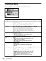
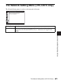
The Network Setting Menu
(VPL-DX15 only) .........................55
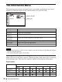
The Information Menu .....................56
Maintenance
Replacing the Lamp .........................58
Cleaning the Air Filter .....................60
Others
Troubleshooting ...............................61
Messages List .............................65
Specifications ...................................66
Installing the Projector and Installation
Diagram ........................................70
Floor Installation
(Front Projection) ....................70
Ceiling Installation
(Front Projection) ....................72
Dimensions .......................................74
Index .................................................77
Table of Contents
9
Precautions
On safety
• Check that the operating voltage of your
unit is identical with the voltage of your
local power supply. If voltage adaptation is
required, consult with qualified Sony
personnel.
• Should any liquid or solid object fall into
the cabinet, unplug the unit and have it
checked by qualified Sony personnel
before operating it further.
• Unplug the unit from the wall outlet if it is
not to be used for several days.
• To disconnect the cord, pull it out by the
plug. Never pull the cord itself.
• The wall outlet should be near the unit and
easily accessible.
• The unit is not disconnected from the AC
power source (mains) as long as it is
connected to the wall outlet, even if the
unit itself has been turned off.
• Do not look into the lens while the lamp is
on.
• Do not place your hand or objects near the
ventilation holes (exhaust) — the air
coming out is hot.
• Be careful not to catch your fingers by the
adjuster when you adjust the height of the
unit. Do not push hard on the top of the
unit with the adjuster out.
• Be sure to grasp both sides of the unit with
both hands when carrying the unit.
On illumination
• To obtain the best picture, the front of the
screen should not be exposed to direct
lighting or sunlight.
• Cover any windows that face the screen
with opaque draperies.
• It is desirable to install the unit in a room
where floor and walls are not of lightreflecting material. If the floor and walls
are of reflecting material, it is
recommended that the carpet and wall
paper be changed to a dark color.
10
Precautions
On preventing internal heat buildup
The unit is equipped with ventilation holes
(intake) at the bottom and ventilation holes
(exhaust) at the side. Do not block or place
anything near these holes, or internal heat
build-up may occur, causing picture
degradation or damage to the unit.
On cleaning
Before cleaning
Be sure to disconnect the AC power cord
from the AC outlet.
On cleaning the air filter
• Clean the air filter whenever you replace
the lamp.
• Refer to the “Cleaning the Air Filter” on
page 60 for the air filter cleaning.
On cleaning the lens
The lens surface is especially treated to
reduce reflection of light.
As incorrect maintenance may impair the
performance of the projector, take care with
respect to the following:
• Avoid touching the lens. To remove dust
on the lens, use a soft dry cloth. Do not use
a damp cloth, detergent solution, or
thinner.
• Wipe the lens gently with a soft cloth such
as a cleaning cloth or glass cleaning cloth.
• Stubborn stains may be removed with a
soft cloth such as a cleaning cloth or glass
cleaning cloth lightly dampened with
water.
• Never use solvent such as alcohol, benzene
or thinner, or acid, alkaline or abrasive
detergent, or chemical cleaning cloth, as
they will damage the lens surface.
On cleaning the cabinet
• Clean the cabinet gently with a soft dry
cloth. Stubborn stains may be removed
with a cloth lightly dampened with mild
detergent solution, followed by wiping
with a soft dry cloth.
• Use of alcohol, benzene, thinner or
insecticide may damage the finish of the
cabinet or remove the indications on the
cabinet. Do not use these chemicals.
• If you rub on the cabinet with a stained
cloth, the cabinet may be scratched.
• If the cabinet is in contact with a rubber or
vinyl resin product for a long period of
time, the finish of the cabinet may
deteriorate or the coating may come off.
On LCD projector
The LCD projector is manufactured using
high-precision technology. You may,
however, see tiny black points and/or bright
points (red, blue, or green) that continuously
appear on the LCD projector. This is a
normal result of the manufacturing process
and does not indicate a malfunction.
Also, when you use multiple LCD projectors
to project onto a screen, even if they are of
the same model, the color reproduction
among projectors may vary, since color
balance may be set differently from one
projector to the next.
Notes on Installation
and Usage
Unsuitable Installation
Do not install the unit in the following
situations. These installations may cause
malfunction or damage to the unit.
Poorly ventilated
• Allow adequate air circulation to prevent
internal heat build-up. Do not place the
unit on surfaces (rugs, blankets, etc.) or
near materials (curtains, draperies) that
may block the ventilation holes.
• When the internal heat builds up due to the
block-up, the temperature sensor will
function with the message “High temp.!
Lamp off in 1 min.” The power will be
turned off automatically after one minute.
• Leave space of more than 30 cm (11 7/8
inches) around the unit.
• Be careful that the ventilation holes may
inhale tininess such as a piece of paper.
Highly heated and humid
• Avoid installing the unit in a location
where the temperature or humidity is very
high, or temperature is very low.
• To avoid moisture condensation, do not
install the unit in a location where the
temperature may rise rapidly.
Notes on Installation and Usage
11
Subject to direct cool or warm air
from an air-conditioner
Installing in such a location may cause
malfunction of the unit due to moisture
condensation or rise in temperature.
Near a heat or smoke sensor
Malfunction of the sensor may be caused.
Very dusty, extremely smoky
Avoid installing the unit in a very dusty or
extremely smoky environment. Otherwise,
the air filter will become obstructed, and this
may cause a malfunction of the unit or
damage it. Dust preventing the air passing
through the filter may cause a rise in the
internal temperature of the unit. Clean the air
filter whenever you replace the lamp.
12
Notes on Installation and Usage
Usage in High Altitude
When using the unit at an altitude of 1,500 m
or higher, set the “High Altitude Mode” to
“On” in the Setup menu. Failing to set this
mode when using the unit at high altitudes
could have adverse effects, such as reducing
the reliability of certain components.
Note on the screen
When using a screen with an uneven surface,
stripes pattern may rarely appear on the
screen depending on the distance between
the screen and the unit or the zooming
magnifications. This is not a malfunction of
the unit.
Unsuitable Conditions
Do not use the unit under the following
conditions.
Do not topple the unit
Avoid using as the unit topples over on its
side. It may cause malfunction.
Do not tilt right/left
Avoid using as the unit tilts right or left more
than 20 degrees. These installations may
cause malfunction.
Do not block the ventilation holes
Avoid using something to cover over the
ventilation holes (exhaust/intake);
otherwise, the internal heat may build up.
Do not place a blocking object just
in front of the lens
Do not place any object just in front of the
lens that may block the light during
projection. Heat from the light may damage
the object. Use the picture muting function
key to cut off the picture.
Notes on Installation and Usage
13
B Overview
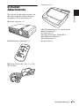
About the Supplied
Manuals
The following manuals are supplied with the
projector.
Manuals
Safety Regulations (separately
printed manual)
This manual describes important notes and
cautions to which you have to pay attention
when handling and using this projector.
Quick Reference Manual (separately
printed manual)
This manual describes basic operations for
projecting pictures after you have made the
required connections.
Operating Instructions (on the CDROM) (this manual)
This Operating Instructions describes the
setup and operations of this projector.
Operating Instructions for Network/
USB file Viewer (VPL-DX15 only) (on
the CD-ROM)
This Operating Instructions describes about
the network function and how to use the
USB file viewer.
Note
You must have Adobe Acrobat Reader 5.0 or
higher installed to read the Operating
Instructions stored on the CD-ROM.
14
About the Supplied Manuals
This manual contains explanations for the
VPL-DX10, VPL-DX11 and VPL-DX15
together. Be aware that the VPL-DX15 is
mainly used for explanation of the display,
and there may be an item that is not
displayed due to the model.
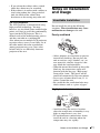
Included
Attachments
Carrying case (1)
Overview
The package for this product includes the
Main unit (projector) and the following
attachments. Check them before use.
Main unit (projector) (1)
RM-PJ6 Remote Commander (1)
CR2025 Lithium battery (1) (installed in the
Remote Commander)
AC power cord (1)
Operating Instructions (CD-ROM) (1)
Quick Reference Manual (1)
Safety Regulations (1)
Security Label (1)
HD D-sub 15 pin cable (2 m) (1) (1-791992-51/Sony)
Included Attachments
15
Location and Function of Controls (Main
Unit)
Top/Front/Side
1
2
3
6
0
7
4
5
4
Rear/Side/Bottom
qa
8
qa
9
0
4
qs
4
a Zoom ring
Adjusts the picture size.
16
Location and Function of Controls (Main Unit)
qd
b Focus ring
Adjusts the picture focus.
c Lens shutter lever
If you operate the Lens shutter lever
manually, the image is interrupted. In
this case, the video signal is not
projected to the screen.
Overview
d Adjusters (front pad)
Use the adjusters for minor tilt
adjustment of the projected picture.
For details, see “Using the adjuster” on
page 26.
e Lens/Lens shutter
f Control Panel
For details, see “Control Panel” on
page 18.
g Remote control detector
h Security lock
Connects to an optional security cable
(from Kensington).
For details, see “Security Lock
(Mechanical)” on page 36.
i Connector Panel
For details, see “Connector Panel” on
page 19.
j Ventilation holes (intake)
k Ventilation holes (exhaust)
l Lamp cover
m Ventilation holes (intake)/Air
filter cover
Notes on ventilation holes
• Do not place anything near the ventilation
holes as this may cause internal heat buildup.
• Do not place your hand near the ventilation
holes and the circumference as this may
cause injury.
• To maintain optimal performance, clean the
air filter every 500 hours.
For details, see “Cleaning the Air Filter” on
page 60.
Location and Function of Controls (Main Unit)
17
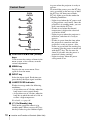
Control Panel
PUSH
ENTER
1
MENU
2
INPUT
3
LAMP/COVER
4
5
Top of projector
a PUSH ENTER/v/V/b/B (Arrow)
keys
Used to enter the settings of items in the
menu system, select a menu, or make
various adjustments.
b MENU key
Displays the on-screen menu. Press
again to clear the menu.
c INPUT key
Select the input signal. Each time you
press the key the input signal switches.
d LAMP/COVER indicator
Flashes in orange under the following
conditions:
• A repetition rate of 2 flashes when the
lamp cover is not secured firmly.
• A repetition rate of 3 flashes when the
lamp has reached the end of its life or
reaches a high temperature.
For details, see page 64.
e ?/1 (On/Standby) key
Turns on the projector when it is in
standby mode. When you press ?/1 key,
this key flashes in green and then lights
18
Location and Function of Controls (Main Unit)
in green when the projector is ready to
operate.
To turn off the power, press the ?/1 key
twice according to the message or hold
the ?/1 key for about two seconds.
?/1 key lights up or flashes under the
following conditions:
– Lights in red when the AC power cord
is plugged into a wall outlet. Once the
projector is in standby mode, you can
turn it on with the ?/1 key.
– Flashes in red when the internal
temperature is high or the electrical
system has failed.
– Lights in green when the projector is
turned on, and when it is ready to
operate.
– Flashes in green from the time when
the projector is turned on until the
projector is ready to operate. Also,
flashes in green while the cooling fan
is running after the power is turned off
with the ?/1 key. The fan runs for
about 90 seconds after the power is
turned off (during cooling).
– Lights in orange when the power
saving mode is on.
Connector Panel
Rear
a
4
5 6 78
(network) connector (RJ-45)
(VPL-DX15 only)
Connects to the LAN cable when the
network function is in use.
CAUTION
For safety, do not connect the connector
for peripheral device wiring that might
have excessive voltage to this port.
b
(USB) connector (type A)
(VPL-DX15 only)
Uses to view files saved on media with
USB connection.
Note
The projector cannot be connected with the
computer by connecting the USB cable to
the USB connector on the projector.
Overview
1 2 3
For details, see “Connecting a
Computer” on page 23 and
“Connecting a VCR” on page 24.
e S VIDEO connector (mini DIN 4pin)
Connects to the S video output (Y/C
video output) of video equipment.
f VIDEO connector (phono type)
Connects to the composite video output
of video equipment.
g AUDIO connector
Connects to the audio output of video
equipment.
h AC IN socket
Connects the supplied AC power cord.
c Speaker
Outputs sound from signals input via the
AUDIO terminals.
d INPUT A (Analog RGB)
connector (HD D-sub 15-pin,
female)
Inputs a computer signal, video GBR
signal, component signal, or DTV signal
depending on the connected equipment.
Connects to the output connector of
equipment using the supplied cable or an
optional cable.
Location and Function of Controls (Main Unit)
19
Remote Commander
The keys that have the same names as those
on the control panel function identically.
9
1
INPUT NETWORK USB
2
3
MENU
4
APA
0
qa
qs
ENTER
RESET
5
6
7
8
AUTO FOCUS LENS
KEYSTONE
/TILT
PIC MUTING
D ZOOM VOLUME FREEZE AUDIO MUTING
qd
qf
qg
qh
qj
a NETWORK key
One press of this key starts the network
function.
For details, refer to “Operating
Instructions (For Network/USB File
Viewer)” on the supplied CD-ROM.
g D ZOOM (Digital Zoom) +/– key
Press this to active the digital zoom
For details, see “Zoom a Part of the
Image (Digital Zoom)” on page 36.
h VOLUME +/– keys
For adjusting the volume from the
speakers.
i Infrared transmitter
j ?/1 (On/Standby) key
k USB key
One press of this key starts the USB file
viewer function.
For details, refer to “Operating
Instructions (For Network/USB File
Viewer)” on the supplied CD-ROM.
Note
No key may function immediately after
connecting the AC power cord, as the
unit is starting up.
l APA (Auto Pixel Alignment) key
Executes APA.
For details, see “Adjusting the Image
Quality (Smart APA)” on page 39.
m LENS key
Note
No key may function immediately after
connecting the AC power cord, as the
unit is starting up.
b INPUT key
c MENU key
d ENTER/v/V/b/B (Arrow) keys
e RESET key
Use this to reset the menu, to restore the
default value for the adjusted item, and
others. Use it also for the digital zoom
(page 36).
f AUTO FOCUS key
This function is not provided in this
projector.
This function is not provided in this
projector.
n KEYSTONE (Trapezoidal
distortion correction) /TILT key
Press this to adjust the trapezoidal
distortion.
For details, see “Correcting the
Trapezoidal Distortion Automatically
(Auto V Keystone Correction)” on page
31.
Tilt function is not provided in this
projector.
o PIC MUTING key
p AUDIO MUTING key
q FREEZE key
For pausing the projected image.
20
Remote Commander
For details, see “To Freeze the Image
Projected (Freeze)” on page 37.
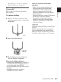
Before using the Remote
Commander
To replace a battery
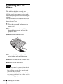
1
Pull out the battery cover by a thin
stick inserting to a hole, as shown the
illustration.
Overview
Pull out the clear film from the lithium
battery holder.
Notes on Remote Commander
operation
• Make sure that nothing obstructs the
infrared beam between the Remote
Commander and the remote control
detector on the projector. Direct the
Remote Commander toward the remote
control detector.
• The operation range is limited. The shorter
the distance between the Remote
Commander and the remote control
detector is, the wider the angle within
which the commander can control the
projector becomes.
CAUTION
Danger of explosion if battery is incorrectly
replaced.
Replace only with the same or equivalent
type recommended by the manufacturer.
When you dispose of the battery, you must
obey the law in the relative area or country.
Rear
2
Install the lithium battery.
Face the +
side up.
3
Put the lithium battery holder back
into the Remote Commander.
Notes on the lithium battery
• A button type lithium battery (CR2025) is
used in the Remote Commander. Do not
use batteries other than CR2025.
• Keep the lithium battery out of the reach of
children.
• Should the battery be swallowed,
immediately consult a doctor.
Remote Commander
21
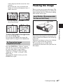
B Projecting the Picture
Installing the
Projector
Connecting the
Projector
This unit can be operated on a floor or
desktop (floor installation), but also can be
suspended from a ceiling with a dedicated
mounting device (ceiling installation).
For details, see “Installing the Projector and
Installation Diagram” on page 70.
When you connect the projector,
make sure to:
• Turn off all equipment before making any
connections.
• Use the proper cables for each connection.
• Insert the cable plugs firmly; loose
connections may reduce performance of
picture signals. When pulling out a cable,
be sure to pull it out by the plug, not the
cable itself.
For VPL-DX15, when connecting to a
(Network) connector or
(USB)
connector, see “Operating Instructions for
Network/USB File Viewer” stored on the
CD-ROM.
22
Installing the Projector / Connecting the Projector
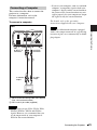
Connecting a Computer
This section describes how to connect the
projector to a computer.
For more information, refer to the
computer’s instruction manual.
• If you set your computer, such as a notebook
computer, to output the signal to both your
computer’s display and the external monitor,
the picture of the external monitor may not
appear properly. Set your computer to output
the signal to only the external monitor.
For details, refer to the operating
instructions supplied with your computer.
To connect a computer
Rear
Note
Projecting the Picture
To connect a Macintosh computer equipped
with a video output connector of a type having
two rows of pins, use a commercially available
plug adaptor.
to AUDIO
connector
to INPUT A
connector
2 1
to audio
output
to monitor
output
Computer
A Stereo audio connecting cable (not supplied)
(Use a no-resistance cable.)
B HD D-sub 15-pin cable (supplied)
Notes
• The projector accepts VGA, SVGA, XGA,
WXGA, WXGA+, SXGA and SXGA+
signals. However, we recommend that you
set the output mode of your computer to
XGA for the external monitor.
Connecting the Projector
23
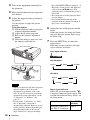
To connect to a video GBR/
Component output connector
Connecting a VCR
This section describes how to connect the
projector to a VCR.
For more information, refer to the
instruction manuals of the equipment you
are connecting.
Rear
To connect to a video output
connector
Rear
to INPUT A
connector
to AUDIO
connector
2
to VIDEO
connector
to
S VIDEO
connector
2
1
to AUDIO
connector
1
to video
GBR/
component
output
to audio
output
(L/R)
VCR
to S
video
output
to video
output
to audio
output
(L/R)
A Stereo audio connecting cable (not supplied)
(Use a no-resistance cable.)
B Signal Cable (not supplied)
HD D-sub 15-pin (male) ↔ 3 × phono plug
Notes
VCR
A Stereo audio connecting cable (not supplied)
(Use a no-resistance cable.)
B Video cable (not supplied) or S-Video cable
(not supplied)
24
Connecting the Projector
• Set the aspect ratio using “Aspect” on the
Screen menu according to the input signal.
• When you connect the projector to a video
GBR output connector, select “Video GBR”
or when you connect the projector to a
component output connector, select
“Component” with the “Input-A Signal Sel.”
setting on the Setup menu.
Connecting to a Network
(VPL-DX15 only)
Projecting
To see how to connect to a network, refer to
“Operating Instructions for Network/USB
File Viewer” included on the supplied CDROM.
PUSH
ENTER
Connecting a USB memory
(VPL-DX15 only)
MENU
7
INPUT
LAMP/COVER
1
2
to a wall outlet
6
4
Projecting the Picture
To see how to connect a USB memory, refer
to “Operating Instructions for Network/USB
File Viewer” included on the supplied CDROM.
5
7
2
INPUT NETWORK USB
MENU
APA
5
ENTER
RESET
AUTO FOCUS LENS
KEYSTONE
/TILT
PIC MUTING
D ZOOM VOLUME FREEZE AUDIO MUTING
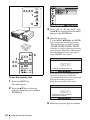
1
Plug the AC power cord into a wall
outlet, then connect all equipment.
The ?/1 key lights in red and the
projector goes into standby mode.
2
Press the ?/1 key to turn the power on.
Projecting
25
3
Turn on the equipment connected to
the projector.
4
Move the lens shutter lever to open the
lens shutter.
5
Adjust the upper or lower position of
the picture.
Use the adjuster to adjust the picture
position.
Using the adjuster
1 Lift the projector while pressing the
Adjuster adjustment button.
2 Adjust the tilt of the projector.
3 Release the Adjuster adjustment
button.
4 When fine-tuning is necessary, turn
the Adjuster right and left.
Press the KEYSTONE key to display “V
Keystone” on the screen, and adjust the
value with the v/V/b/B keys. The
adjusted value is valid until the power is
turned off.
• Be careful not to let the projector down
on your fingers.
• Do not push hard on the top of the
projector with the adjuster extended. It
may cause a malfunction.
6
Adjust the size of the picture and the
focus.
Adjust the picture size using the Zoom
ring and adjust the picture focus using
the Focus ring.
7
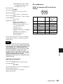
Press the INPUT key to select the
input source.
Each time you press the key, the input
signal switches as follows:
Input signal indicator
VPL-DX10/DX11
Input-A
2
Video
S-Video
Network
USB
13
VPL-DX15
4
Input-A
S-Video
Video
Notes
• When you adjust the tilt of the projector
with the adjuster, the V keystone
adjustment is performed at the same
time. If you do not want to perform the
automatic keystone adjustment, set the
“V Keystone” to “Manual.” (See
page 54.)
• If you set the “V Keystone” to “Auto,”
the “V Keystone” correction is
automatically adjusted. However, it may
not be perfectly adjusted depending on
the room temperature or the screen
angle. In this case, adjust it manually.
26
Projecting
Input signal indicator
Shows the selected input channel. x
is displayed when no signal is input. You
can hide this indicator using “Status” on
the Setup menu.
To input from
Press INPUT
to display
Computer connected to
the INPUT A connector
Input-A
To input from
Press INPUT
to display
Video
Video equipment
connected to the VIDEO
input connector
Video equipment
connected to the
S VIDEO input
connector
projector by pressing certain keys (e.g.,
, etc.), or by
changing your computer’s settings.
or
S-Video
and
USB memory connected USB
to the USB connector
When the selected input is a computer
signal, APA (Auto Pixel Alignment)
functions automatically to adjust the
image from the connected equipment for
clear display.
Note
The key used for switching the computer to
output to the projector varies depending on
the type of computer.
Projecting the Picture
Computer connected to a Network
LAN to use the network
function
For details, see “Adjusting the Image
Quality (Smart APA)” on page 39.
When Network or USB is selected
(VPL-DX15 only)
When Network is selected, the
confirmation display to show
disconnection with USB memory
appears.
When USB is selected, the confirmation
display to show disconnection with the
network equipment appears.
If the network or USB memory is not
connected, or if they are to be turned off,
press the ENTER key.
Note
If “Auto Input Search” is set to “On,” the
projector searches for the signals from the
connected equipment and displays the
input signal where the input signals are
found. In VPL-DX15, if there is no input
signal, “Network” is selected.
For details, see “Auto Input Search” on
page 52.
8
Switch the equipment connected to
output to the projector.
Depending on the type of your
computer, for example a notebook, or an
all-in-one LCD type, you may have to
switch the computer to output to the
Projecting
27
Turning Off the
Power
1
Press the ?/1 key.
“POWER OFF? Please press ?/1 key
again.” appears to confirm that you want
to turn off the power.
Note
The message disappears if you press any
key other than the ?/1 key, or if you do not
press any key for five seconds.
2
Press the ?/1 key again.
The ?/1 key flashes in green and the fan
continues to run to reduce the internal
heat.
3
Unplug the AC power cord from the
wall outlet after the fan stops running
and the ?/1 key lights in red. (Except
when using the Off & Go)
This product can be turned off without
waiting for the fan to stop after your
presentation has finished (Off & Go).
For details, see “Switching off Smoothly
after Presentation (Off & Go)” on page
33.
When you cannot confirm the onscreen message
When you cannot confirm the on-screen
message under certain conditions, you can
turn off the power by holding the ?/1 key for
about two seconds instead of above steps 1
and 2.
To project again immediately
You can make the lamp light by turning on
the power again even, while the ?/1 key is
flashing in green. There may be a delay,
depending on conditions, before the lamp
lights.
28
Turning Off the Power
B Convenient Functions
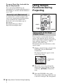
Selecting the Menu Language
You can select one of seventeen languages for displaying the menu and other on-screen
displays. The factory setting is English.
To change the menu language, proceed as follows:
3
Press the MENU key.
The menu appears.
The menu currently selected is shown as
a yellow button.
PUSH
ENTER
4,5,6
3
MENU
LAMP/COVER
1
2
to a wall outlet
(VPL-DX15)
4
Convenient Functions
80
50
50
50
Low
30
INPUT
Press the v or V key to select the
Setup menu, then press the B or
ENTER key.
The selected menu appears.
2
INPUT NETWORK USB
3
MENU
30
APA
4,5,6
ENTER
RESET
AUTO FOCUS LENS
KEYSTONE
/TILT
PIC MUTING
D ZOOM VOLUME FREEZE AUDIO MUTING
1
Plug the AC power cord into a wall
outlet.
2
Press the ?/1 key to turn on the
projector.
The ?/1 key flashes in green, and then
lights in green.
Selecting the Menu Language
29
5
Press the v or V key to select
“Language,” then press the B or
ENTER key.
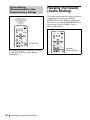
Resetting All Setting
Values
You can reset all setting values to default.
To Change from the Menu
PUSH
ENTER
6
2,3,4
1
MENU
INPUT
Press the v/V/b/B key to select a
language, then press the ENTER key.
LAMP/COVER
The menu changes to the selected
language.
To clear the menu
Press the MENU key.
The menu also disappears automatically if a
key is not pressed for one minute.
INPUT NETWORK USB
1
MENU
APA
2,3,4
ENTER
RESET
RESET
AUTO FOCUS LENS
KEYSTONE
/TILT
PIC MUTING
D ZOOM VOLUME FREEZE AUDIO MUTING
1
Press the MENU key.
The menu appears.
30
Resetting All Setting Values
2
3
Press the v/V key to select the Picture
menu then press the B or ENTER key.
Select “Reset” with the v/V key from
the Picture menu then press the
ENTER key.
4
After the next window has appeared,
select “Yes”, using the b/B key, then
press the ENTER key.
Reset
Do you wish to reset the settings
to default values ?
Yes
This function automatically corrects
trapezoidal distortion due to the projection
angle.
Further Adjusting an Image
That Has Been Automatically
Adjusted
Note
If you wish to switch to auto adjustment
mode after adjusting manually, switch the V
Keystone setting to “Manual” once then
return it to “Auto”.
Convenient Functions
For details, see to page 45.
Correcting the
Trapezoidal
Distortion
Automatically (Auto
V Keystone
Correction)
No
INPUT NETWORK USB
Factory-preset items:
“Contrast,” “Brightness,” “Color,”
“Hue,” “Color Temp.,” “Sharpness,”
“DDE,” “Black Level Adj.,” and
“Gamma Mode” (can be set on Picture
menu).
APA
MENU
2
ENTER
RESET
AUTO FOCUS LENS
KEYSTONE
/TILT
PIC MUTING
To Return the Value of an
Adjusted Item to Default
Press the RESET key on the Remote
Commander.
If you press the RESET key while the item is
being adjusted (the item is displayed in the
window), it returns to the factory preset
value.
1
D ZOOM VOLUME FREEZE AUDIO MUTING
1
Press the KEYSTONE/TILT key.
Correction menu appears.
2
Adjust v/V/b/B with the v/V/b/B
keys.
When the lower side is longer than
the upper side (
)
Adjust the volume so as to decrease it.
When the upper side is longer
than the lower side (
)
Adjust the volume so as to increase it.
Correcting the Trapezoidal Distortion Automatically (Auto V Keystone Correction)
31
The menu automatically goes off in
approximately 5 seconds after operation.
2
Press the v/V key to select the
Installation setting menu then press
the B or ENTER key.
To Change from the Menu
Auto
Lamp Mode
Direct Power ON
PUSH
ENTER
2~6
1
Standard
Off
MENU
INPUT
LAMP/COVER
3
Select “V Keystone” with the v/V key
from the Installation setting menu then
press the ENTER key.
4
Select “Auto” for automatic
correction or “Manual” to correct it
manually. Then, press the ENTER
key.
5
If you selected “Manual”, use the v/
V/b/B keys.
When the lower side is longer than
the upper side (
)
Adjust the volume to decrease it.
When the upper side is longer
than the lower side (
)
Adjust the volume to increase it.
INPUT NETWORK USB
1
MENU
APA
2~6
ENTER
RESET
AUTO FOCUS LENS
PIC MUTING
D ZOOM VOLUME FREEZE AUDIO MUTING
1
Press the MENU key.
The menu appears.
32
6
Press the ENTER key.
KEYSTONE
/TILT
Notes
• The auto V Keystone adjustment may not
correct the trapezoidal distortion perfectly,
depending on the room temperature or the
screen angle.
• Since the V keystone adjustment is an
electronic correction, sometimes the image
will be deteriorated.
Correcting the Trapezoidal Distortion Automatically (Auto V Keystone Correction)
Switching off
Smoothly after
Presentation (Off &
Go)
You can disconnect the power cord
immediately after turning off the unit. So
you can move it readily if necessary.
Notes
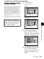
Security Lock (Password)
The projector is equipped with a security
lock function. When you turn the power of
the projector on, you are required to input
the previously set password. If you do not
input the correct password, you will not be
able to project the picture.
Notes
• When the security lock becomes effective,
you are required to input the password only
when you turn the projector on after
disconnecting or reconnecting the cable.
• You will not be able to use the projector if
you forget your password and the password
administrator is not available. Be please
aware that using the security lock can prevent
valid usage in such cases.
Switching off Smoothly after Presentation (Off & Go) / Using the Security Function
Convenient Functions
• Turn off the projector according to the
procedure explained in “Turning Off the
Power” on page 28, then cool it down before
storing the projector in the carrying case.
• When the power is turned on soon after it has
been turned off, it may take some time until
the lamp will light on.
Using the Security
Function
33
PUSH
ENTER
2,3,4,5
1
MENU
INPUT
LAMP/COVER
6
Select “On” of “Security Lock” with
the v/V key from the Function menu
then press the ENTER key.
4
Enter the password.
Use the MENU, v/V/b/B, and ENTER
keys to enter the four-digit password.
(The default initial password setting is
“ENTER, ENTER, ENTER, ENTER.”
After this is entered you can put in your
own password. Therefore, when you use
this function for the first time, please
input “ENTER” four times.)
6
INPUT NETWORK USB
1
2,3,
4,5
3
APA
MENU
Security Lock
Enter password key.
ENTER
RESET
AUTO FOCUS LENS
KEYSTONE
/TILT
Password required for power-on.
PIC MUTING
Use:
D ZOOM VOLUME FREEZE AUDIO MUTING
Next, the screen for entering the new
password is displayed. (Enter the
password on this screen even if you want
to keep the current password.)
Enter the password on this screen.
To use the security lock
1
Cancel: Other key
Press the MENU key.
The menu appears.
2
Security Lock
Enter new password key.
Press the v/V key to select the
Function menu then press the B or
ENTER key.
Power-on cannot be performed
without the password.
Use:
5
34
Using the Security Function
Cancel: Other key
Enter the password again to confirm.
Panel Key Lock
Security Lock
Re-enter new password key.
Be sure to remember this password.
Use:
Cancel: Other key
When “Security Lock enabled!” is
displayed on the menu screen, the
setting for security lock is completed.
The Panel Key Lock function enables
locking of all keys on the control panel on
the topside, which in the case only the
Remote Commander can be used.
1
The menu appears.
2
Press the v/V key to select the
Function menu then press the B or
ENTER key.
3
Select “Panel Key Lock” with the v/V
key from the Function menu then
press the ENTER key.
If “Invalid Password!” is displayed on
the menu screen, perform this procedure
again from step 1.
6
Press the MENU key.
Convenient Functions
Turn the main power off and
disconnect the AC power cord.
The security lock is set to on, then it
becomes effective. The screen used for
entering the password is displayed when
the power is turned on the next time.
Security certification
When the password screen is displayed,
enter the password that was set. If you fail to
enter the correct password after three tries,
the projector cannot be used. In this case,
press the ?/1 key to turn off the power.
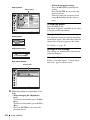
Panel Key Lock
To cancel the security lock
Lock the control panel keys?
1
2
Press the MENU key, then set the
“Security Lock” setting to “off” in the
Function menu.
Enter the password.
Enter the password that was set.
Yes
4
No
Select “Yes” with the b key.
Panel Key Lock comes to be valid.
Note
If you call Sony personnel because you have
forgotten the password, you will be asked to
verify the projector’s serial number and your
identity. (This process may differ in other
countries/regions.) Once your identity has been
confirmed, we will provide you with the
password.
If it is set to “Yes”, the power can be
turned on if you hold the ?/1 key on the
control panel pressed for approximately
10 seconds during Standby mode. While
the projector enters into Standby mode if
the ?/1 key is held pressed for
approximately 10 seconds during power
on.
Using the Security Function
35
To cancel Panel Key Lock with the
key on the projector
Press and hold the MENU key for
approximately 10 seconds while the power is
on. Locking is canceled, and the function is
set to “Off”.
Using Various
Functions During
Projecting
Security Lock (Mechanical)
A commercially available antitheft cable
such as one (manufactured by Kensington)
can be attached to the antitheft lock.
For details, refer to the home page of
Kensington.
Kensington Web page address:
http://www.kensington.com/
INPUT NETWORK USB
APA
MENU
2
ENTER
RESET
RESET
AUTO FOCUS LENS
KEYSTONE
/TILT
PIC MUTING
1,3
D ZOOM VOLUME FREEZE AUDIO MUTING
FREEZE
Zoom a Part of the Image
(Digital Zoom)
You can select a section of the image to
enlarge. This function will be active only
when a signal from a computer is input or an
input signal of “Network” or “USB” is
selected. (VPL-DX15 only)
This function does not work when a video
signal is input.
1
Project a normal image, and press the
D ZOOM + key on the Remote
Commander.
The digital zoom icon appears in the
center of the image.
Digital zoom
icon
2
Move the icon to the point on the
image you want to enlarge. Use the
arrow key (v/V/b/B) to move the
icon.
3
Press the D ZOOM + key again.
The portion of the image where the icon
is located is enlarged. The enlargement
36
Using Various Functions During Projecting
ratio is displayed on the screen for a few
seconds.
By pressing the + key repeatedly, the
image size (ratio of enlargement: max. 4
times) increases.
Pausing the Image
There are two ways to pause the image. The
Lens shutter blocks the image by closing the
shutter outside the lens. The picture muting
shuts off the video signal.
Lens Shutter (Recommended
for Use on the Floor)
Use the arrow key (v/V/b/B) to scroll
the enlarged image.
To Freeze the Image
Projected (Freeze)
Press the FREEZE key. “Freeze” appears
when the key is pressed. This function will
be active only when a signal from a
computer is input or an input signal of
“Network” or “USB” is selected. (VPLDX15 only)
To restore the original screen, press the
FREEZE key again.
Projection is interrupted by closing the lens
shutter with the lens shutter lever on the top
of the unit.
While the lens shutter is closed, an all-black
signal is output inside the projector.
The projector goes to standby mode
approximately two hours after you close the
lens shutter.
Pausing the Image
Convenient Functions
To return the image to its original size
Press the D ZOOM – key.
Just pressing the RESET key returns the
image back to its original size immediately.
Lens shutter
lever
37
Picture Muting
(Recommended for Use
Suspend from a Ceiling)
Pausing the Sound
(Audio Muting)
The sound output from the speakers is muted
temporarily by pressing the AUDIO
MUTING key on the Remote Commander.
To cancel it, press the AUDIO MUTING key
again or press the VOLUME + key to
increase the volume.
INPUT NETWORK USB
MENU
APA
INPUT NETWORK USB
ENTER
APA
MENU
RESET
AUTO FOCUS LENS
KEYSTONE
/TILT
ENTER
PIC MUTING
D ZOOM VOLUME FREEZE AUDIO MUTING
PIC MUTING
RESET
AUTO FOCUS LENS
KEYSTONE
/TILT
PIC MUTING
VOLUME +
D ZOOM VOLUME FREEZE AUDIO MUTING
The projected image is muted by pressing
the PIC MUTING key on the Remote
Commander.
38
Pausing the Sound (Audio Muting)
AUDIO MUTING
Adjusting the Image
Quality (Smart APA)
2
Press the v/V key to select the
Function menu then press the B or
ENTER key.
3
Select “Smart APA” with the v/V key
from the Function menu then press the
B or ENTER key.
4
Select “On” or “Off” with the v/V
key.
APA (Auto Pixel Alignment) automatically
adjusts the picture to be clear when a
computer signal is input. “Phase”, “Pitch”,
and “Shift” on the Screen menu are
automatically adjusted. When “Smart APA”
is set to “On”, this function works whenever
a signal is input.
PUSH
ENTER
MENU
INPUT
LAMP/COVER
On: The APA function automatically
starts when a computer signal is
input so that the image will be
clear. While it is “On”, the APA
key on the Remote Commander
can also be used to the image.
Off: Adjustment starts only when the
APA key on the Remote
Commander is pressed.
Convenient Functions
2~4
1
Notes
INPUT NETWORK USB
1
MENU
APA
2~4
ENTER
RESET
AUTO FOCUS LENS
KEYSTONE
/TILT
PIC MUTING
D ZOOM VOLUME FREEZE AUDIO MUTING
1
Press the MENU key.
• Smart APA is applied only when a computer
signal is input.
• Press the APA key when the full image is
displayed on the screen. If the projected
image includes a black portion around it, the
APA will not work properly and some parts
of the image may not be displayed on the
screen.
• You can cancel the adjustment by pressing
the APA key again while “Adjusting”
appears on the screen.
• The picture may not be adjusted properly
depending on the type of input signal.
• Adjust the “Phase,” “Pitch,” and “Shift”
items in the Screen menu when you adjust
the picture manually.
The menu appears.
Adjusting the Image Quality (Smart APA)
39
Setting the Picture
Mode
2
Press the v/V key to select the Picture
menu then press the B or ENTER key.
3
Select “Picture Mode” with the v/V
key from the Picture menu then press
the B key or ENTER key.
4
Select “Picture Mode” with the v/V
key to suit to the projected image then
press the ENTER key.
The Picture Mode can be set to suit to the
projected image.
The setting value is registered for each
mode.
Note
Adjustable or selectable items are limited in
accordance with the types of the input signal on
some menus.
PUSH
ENTER
2~6
1
MENU
INPUT
LAMP/COVER
Dynamic: Emphasizes the contrast to
produce a “dynamic” picture.
Standard: Makes the picture natural
and well balanced.
Presentation: Makes the picture bright
to be suitable for a presentation
when the signal is input from a
computer or an input signal of
Network* or USB* is selected
(applied only when a computer
signal is input or an input signal of
Network* or USB* is selected).
* VPL-DX15 only
5
INPUT NETWORK USB
1
MENU
The setting values for each mode are
registered individually.
APA
2~6
ENTER
RESET
AUTO FOCUS LENS
KEYSTONE
/TILT
PIC MUTING
D ZOOM VOLUME FREEZE AUDIO MUTING
1
Press the MENU key.
The menu window appears.
40
Setting the Picture Mode
Set the items on the Picture menu as
desired.
6
Press the ENTER key.
The selected mode and its setting values
are registered.
Starting the Network
Function or the USB
File Viewer With One
Keypress (VPL-DX15
only)
The network function or the USB file viewer
can be easily started by pressing the
NETWORK or USB key on the Remote
Commander.
Using the Network
Function (VPL-DX15
only)
You can use the following functions by using
the network function of this product.
For details, refer to “Operating Instructions
for Network/USB File Viewer” included on
the supplied CD-ROM.
INPUT NETWORK USB
USB
MENU
APA
NETWORK
ENTER
ENTER
RESET
KEYSTONE
AUTO FOCUS LENS
/TILT
PIC MUTING
D ZOOM VOLUME FREEZE AUDIO MUTING
Convenient Functions
INPUT
By pressing the NETWORK key on
the Remote Commander
The network function starts.
By pressing the USB key on the
Remote Commander
The USB file viewer starts.
Starting the Network Function or the USB File Viewer With One Keypress (VPL-DX15 only) /
Using the Network Function (VPL-DX15 only)
41
Projecting the File in
the USB Memory
Directly (VPL-DX15
only)
The file in the USB memory connected to
the
(USB) port can be displayed
directly on the projected display.
For details, refer to “Operating Instructions
for Network/USB File Viewer” included on
the supplied CD-ROM.
42
Projecting the File in the USB Memory Directly (VPL-DX15 only)
B Adjustments and Settings Using a Menu
Using a MENU
1
Press the MENU key.
The menu appears.
VPL-DX15
The projector is equipped with an on-screen
menu for making various adjustments and
settings. Some of the adjustable/setting
items are displayed in a pop-up menu, in a
setting menu or adjustment menu with no
main menu, or in the next menu window. If
you select an item name followed by an
arrow (B), the next menu window with the
setting items appears.
To change the on-screen menu language, see
“Selecting the Menu Language” on page 29.
VPL-DX10/DX11
This manual contains explanations for the
VPL-DX10/DX11 and VPL-DX15 all
together. Be aware that the VPL-DX15 is
mainly used for explanation of the display,
and there may be an item that is not
displayed due to the model.
Use the v or V key to select a menu,
then press the B or ENTER key.
The items that can be set or adjusted
with the selected menu appear. The item
presently selected is shown in yellow.
3
Adjustments and Settings Using a Menu
2
Use the v or V key to select the item,
then press the B or ENTER key.
The setting items are displayed in a popup menu, in a setting menu, in an
adjustment menu or in the next menu
window.
Using a MENU
43
Pop-up menu
Setting items
• When changing the setting:
Press the v or V key to change the
setting.
Press the ENTER key to restore the
previous screen.
You can restore the previous screen
using b depending on the selected
item.
To clear the menu
Press the MENU key.
The menu disappears automatically if a key
is not pressed for one minute.
Unadjustable items
Setting menu
The adjustable items are limited depending
on the input signals. The items that cannot be
adjusted or set do not appear in the menu.
For details, see page 56.
Adjustment menu
Storage of the settings
The settings are automatically stored in the
projector memory.
If no signal is input
Next menu window
Setting items
4
Make the setting or adjustment of an
item.
• When changing the adjustment
level:
To increase the number, press the v or
B key.
To decrease the number, press the V or
b key.
Press the ENTER key to restore the
previous screen.
44
Using a MENU
If there is no input signal, “Cannot adjust
this item.” appears on the screen.
The Picture Menu
The Picture menu is used for adjusting the picture.
Items that can be adjusted or set depend on the kind of input signals.
For details, see “Input signals and adjustable/setting items” on page 56.
When the video signal is input
When the signal is input from a computer
Functions
Picture Mode
Set according to
Selects the picture mode.
the input signal
A setting value is stored for each setting item.
• Dynamic: Emphasizes the contrast to produce a
“dynamic” picture.
• Standard: Makes the picture be natural and well
balanced.
• Presentation: Makes the picture bright to be suitable for
a presentation when the signal is input from a computer
or an input signal of Network* or USB* is selected.
Initial setting
Reset
The following settings are initialized to their factory preset –
values: “Contrast”, “Brightness”, “Color”, “Hue”, “Color
Temp.”, “Sharpness”, “DDE”, “Black Level Adj.”, and
“Gamma Mode” in the Picture menu.
For details, see “Resetting All Setting Values” on page
30.
Contrast
Adjusts the contrast of pictures.
The higher the setting, the greater the contrast. The lower
the setting, the lower the contrast.
80
Brightness
Adjusts the brightness of the picture.
The higher the setting, the brighter the picture. The lower
the setting, the darker the picture.
50
Color
Adjusts the intensity of the color density.
The higher the setting, the greater the intensity. The lower
the setting, the lower the intensity.
50
Hue
Adjusts the color tone.
The higher the setting, the more greenish the picture
becomes. The lower the setting, the more reddish the
picture becomes.
50
* VPL-DX15 only
The Picture Menu
Adjustments and Settings Using a Menu
Setting items
45
Setting items
Functions
Initial setting
Color Temp.
Adjusts the color temperature.
• High: Gives white colors a blue tint.
• Low: Gives white colors a red tint.
Low
Sharpness
Adjusts the sharpness of the image.
The higher the setting, the sharper the picture. The lower
the setting, the softer the picture, thus reducing the noise.
30
DDE (Dynamic According to the film source you have selected, make a
Film
setting for playback.
Detail
• Film: Normally, select this option. Reproduces the 2-3
Enhancer)
Pull-Down film sources with smooth picture movement.
When the video signal with a format other than the 2-3
Pull-Down is input, “Progressive” is automatically
selected.
• Progressive: Converts an interlace format video signal to
a progressive format.
• Off: Plays a video signal in an interlace format without
converting.
Black Level
Adj. (Adjust)
Dark parts will be clear.
Set according to the input signal source.
• High: Gives higher emphasis to the black color.
• Low: Gives lower emphasis to the black color.
• Off: Cancels this feature.
Off
Gamma Mode
Selects a gamma correction curve.
Graphics
• Graphics: Improves the reproduction of halftones.
Photos can be reproduced in natural tones.
• Text: Contrasts black and white. Suitable for images that
contain lots of text.
Notes
• When the “Picture Mode” is set to “Presentation”, the setting item of “Color Temp.” is not
displayed.
• For Picture Mode, a part of the setting items cannot be displayed on the screen according to the
input signal.
• The Picture Mode setting is common between Network and USB. (VPL-DX15 only)
46
The Picture Menu
The Screen Menu
The Screen menu is used to adjust the input signal. You can also adjust the aspect ratio of the
picture.
Items that can be adjusted or set depend on the kind of input signals.
For details, see “Input signals and adjustable/setting items” on page 56.
Aspect
Adjust Signal
Full 1
,
Functions
Initial setting
Aspect (When the
video signal is
input)
Sets the aspect ratio of the picture to be displayed for Set according to
the current input signal. This item is enabled only
the input signal
when an video signal (preset memory numbers 1 to 11)
is input.
• Zoom: Select this when black bands are displayed in
both sides by the squeeze signal.
• 4:3: Select to view a picture with normal 4:3 aspect
ratio.
• 16:9: Select to view a picture squeezed.
Aspect (When the
computer signal is
input)
Sets the aspect ratio of the picture to be displayed for Set according to
the current input signal. This item is enabled only
the input signal
when an PC signal (preset memory numbers 21 to 63)
is input.
• Full1: Displays a picture vertically or horizontally to
fill the screen without changing the aspect ratio of the
original picture.
• Normal: Displays the picture while matching one
pixel of input picture element to that of the LCD. The
picture will be clear but the picture size will be
smaller.
• 4:3: Makes the aspect ratio 4:3.
• 16:9: Makes the aspect ratio 16:9.
The Screen Menu
Adjustments and Settings Using a Menu
Setting items
47
Setting items
Functions
Adjust Signal
APA (Auto
Pixel
Alignment)
Executes the APA when you press the ENTER key.
The APA function adjusts PHASE, PITCH, and SHIFT
automatically to suit to the input signal.
The APA function can be used only for a computer
signal.
For details, see “Adjusting the Image Quality (Smart
APA)” on page 39.
Phase
Adjusts the dot phase of the panel and the computer
signal, when the computer signal is input.
Adjusts the picture to the point where it looks clearest.
Pitch
Adjusts the horizontal size of the picture from a
computer.
The higher the setting, the wider the picture. The lower
the setting, the narrower the picture. Adjust the setting
to match the number of dots of the input signal.
Shift
Adjusts the position of the picture.
• H: As the setting for H (horizontal) increases, the
picture moves to the right, and as the setting
decreases, the picture moves to the left. Use b/B
key to adjust the horizontal position.
• V: As the setting for V (vertical) increases, the
picture moves up, and as the setting decreases, the
picture moves down. Use v/V key to adjust the
vertical position.
Initial setting
Set according to
the input signal
Note
For Aspect, “Aspect” itself or a part of the setting items cannot be displayed on the screen according
to the input signal.
48
The Screen Menu
About the Preset Memory No.
Adjustments and Settings Using a Menu
This projector has 46 types (VPL-DX15)/45
types (VPL-DX10/DX11) of preset data for
input signals (the preset memory). When a
preset signal is input, the projector
automatically detects the signal type and
recalls the data for the signal from the preset
memory to adjust it to an optimum picture.
The memory number and signal type of that
signal are displayed on the Information
menu (page 56). You can also adjust the
preset data through the Screen menu.
This projector has 20 types of user memories
for Input-A into which you can save the
setting of the adjusted data for an unpreset
input signal.
When an unpreset signal is input for the first
time, a memory number is displayed as 0.
When you adjust the data of the signal using
the Screen menu, it will be registered in the
projector. If more than 20 user memory
items are registered, the newest memory
always overwrites the oldest one.
See the chart on page 68 to find if the signal
is registered in the preset memory.
Notes
• When “Aspect” of the Screen menu is set to
other than “Zoom”, a part of the screen may
be displayed in black.
• Note that if the projector is used for profit or
for public viewing, modifying the original
picture by switching to the aspect mode may
constitute an infringement of the rights of
authors or producers, which are legally
protected.
The Screen Menu
49
The Setup Menu
The Setup menu is used for changing the settings of the projector.
50
Setting items
Functions
Initial setting
Status
• On: Displays on-screen information (menu, etc.) on
the projection screen.
• Off: Turns off the on-screen displays except for the
menus, message when turning off the power, and
warning messages.
On
Language
English
Selects the language used in the menu and on-screen
displays. Available languages are: English, Dutch,
French, Italian, German, Spanish, Portuguese, Russian,
Swedish, Norwegian, Japanese, Chinese (Simplified
Chinese), Chinese (Traditional Chinese), Korean, Thai,
Arabic and Turkish.
Start Up Image
• On: Displays the Start Up Image on the screen after
turning on the power.
• Off: Does not displays the Start Up Image on the
screen after turning on the power.
On
High Altitude
Mode
Uses this item when using the projector at high
altitudes.
• On: Use this setting when using the projector at an
altitude of 1,500 m or higher.
• Off: Use this setting when using the projector at
normal altitudes.
Off
Standby Mode
• Standard: Lowers the power consumption in
standby mode.
• Low: The power consumption in standby is more
lowered.
Standard
Power Saving
Mode
Selects the power saving mode.
• Lamp Cutoff: The lamp goes off and the ?/1 key
lights in orange if no signal is input for 10 minutes.
The lamp lights again when a signal is input or any
key is pressed.
• Standby: The projector goes into standby mode and
the ?/1 key lights in red if no signal is input for 10
minutes. To use it, turn on the power again.
• Off: The projector does not go into power saving
mode.
Off
The Setup Menu
Setting items
Functions
Initial setting
Volume
Adjusts the volume.
30
Input-A Signal Sel. Selects the type of signal input from the equipment
connected to the INPUT A connector.
Selects the type of signal input from the equipment by
selecting “Input-A” with the INPUT key.
• Auto: Selects the input signal type automatically.
• Computer: Inputs the signal from a computer.
• Video GBR: Inputs the signal from a TV game or
HDTV broadcast.
• Component: Inputs the component signal from a
DVD player/recorder, Blu-ray Disc player, digital
tuner, etc.
Auto
Color System
Auto
Selects the color system of the input signal.
• Auto: Selects the color system of the input signal
automatically from among NTSC3.58, PAL, SECAM,
NTSC4.43, PAL-M, PAL-N, or PAL60.
• “NTSC3.58”–“PAL-N”: Allows you to set the color
system to the selected system manually.
Lamp Timer Reset
When replacing the lamps, reset the lamp timer.
–
Notes
The Setup Menu
Adjustments and Settings Using a Menu
• If you turn on “High Altitude Mode” to “On” at an altitude less than 1,500 m (4,921 feet), the
projector may reduce the reliability of the lamp.
• When “High Altitude Mode” is set to “On”, the number of turns of the fan increases, and the
fan noise becomes slightly louder.
• If “Standby Mode” is set to “Low,” the network and network control function cannot be
operated while the unit is in standby mode.
• When the input signal is not displayed correctly even if “Input-A Signal Sel.” set to “Auto,”
select the item according to the input signal.
• Normally, set “Color System” to “Auto.” If the picture is distorted or colorless, select the
color system appropriate for the input signal.
51
The Function Menu
The Function menu is used for changing the settings of the various functions of the projector.
52
Setting items
Functions
Smart APA
Executes APA automatically when a computer signal is On
input.
For details, see “Adjusting the Image Quality (Smart
APA)” on page 39.
• On: For Smart APA to be active
• Off: For Smart APA to be inactive
Auto Input Search
Detects the input signal and displays the detected input Off
signal automatically when the INPUT key is pressed.
• On: Checks if an input signal of Input-A, Network*,
USB*, Video and S-Video in order when the INPUT
key is pressed, and then displays the input terminal at
which the input signal is detected. (* VPL-DX15
only)
Network and USB are always displayed, as they have
input signals (VPL-DX15 only).
• Off: Sets when you want to select an input selector
with no input signal, or you want to switch the setting
manually.
Background
Selects the background color of the screen when no
signal is input.
• Black: The background color will be black.
• Blue: The background color will be blue.
Panel Key Lock
Locks all the control panel keys of the projector so that Off
the projector can be operated only with the Remote
Commander.
• On: For Panel Key Lock to be active
For details, see “Using the Security Function” on
page 33.
To release the lock with the projector, press and hold
the MENU key for about 10 seconds when the power
is on. The lock will be released and “Panel Key
Lock” is automatically set to “Off.”
• Off: For Panel Key Lock to be inactive
The Function Menu
Initial setting
Blue
Setting items
Functions
Initial setting
Security Lock
Sets whether to require the user to input a password
when turning on the power.
• On: For Security Lock to be active
For details, see “Using the Security Function” on
page 33.
• Off: For Security Lock to be inactive
Off
Notes
• Press the APA key when the full image is displayed on the screen. If the projected image includes
a black portion around it, the APA function will not work properly and some parts of the image
may not be displayed on the screen.
• You can cancel the adjustment by pressing the APA key again while “Adjusting” appears on the
screen.
• For APA, the picture may not be adjusted properly depending on the type of input signal.
• Adjust the “Phase,” “Pitch,” and “Shift” items in the Screen menu when you adjust the picture
manually.
Adjustments and Settings Using a Menu
The Function Menu
53
The Installation Menu
The Installation menu is used for changing the settings of the projector.
Auto
Lamp Mode
Direct Power ON
Standard
Off
Setting items
Functions
Initial setting
V Keystone
Sets Auto V Keystone correction.
• Auto: For Auto V Keystone correction to be active
• Manual: For Auto V Keystone correction to be inactive
For details, see “Correcting the Trapezoidal Distortion
Automatically (Auto V Keystone Correction)” on page
31.
Auto
Image Flip
Flips the picture on the screen horizontally and/or
vertically.
Use this item for installation for rear projection.
• HV: Flips the picture horizontally and vertically.
• H: Flips the picture horizontally.
• V: Flips the picture vertically.
• Off: The picture does not flip.
Off
Lamp Mode
Sets the lamp brightness used during the projection.
Standard
• High: For the projected image to be brighter than
Standard
Select this when ambient lighting is too bright to view the
display clearly.
• Standard: For the projected image in standard brightness
Direct Power On Set to “On” if you are using a circuit breaker to turn the
power on/off the entire system.
You can turn the power on/off without pressing the ?/1
key.
Off
Notes
• Since the V keystone adjustment is an electronic correction, sometimes the image will be
deteriorated.
• When the Lamp Mode is set to “High”, the sound from the fan to cool the lamp, etc. is often
excessive.
54
The Installation Menu
The Network Setting Menu (VPL-DX15 only)
The Network Setting menu is used to set the network of this unit.
To Network Setting
Switches to Network Setting window
when you press [ENTER].
Setting items
Functions
Network Setting
The network setting window appears. For details, refer to “Operating
Instructions For Network/USB File Viewer” included on the supplied CDROM.
Adjustments and Settings Using a Menu
The Network Setting Menu (VPL-DX15 only)
55
The Information Menu
The Information menu displays the model name, serial number, the horizontal and vertical
frequencies of the input signal and the cumulated hours of usage of the lamp.
VPL-DX15
Memory number
Signal type
Setting items
Functions
Model Name
Displays the model name.
Serial No.
Displays the serial number.
fH (horizontal
frequency)
Displays the horizontal frequency of the input signal.
fV (vertical
frequency)
Displays the vertical frequency of the input signal.
Memory No.
Displays the preset memory number of the input signal.
Signal Type
Displays the type of the input signal.
Lamp Timer
Indicates the total usage time of a lamp.
Notes
• fH (horizontal frequency) and fV(vertical frequency) may not be displayed depending on the input
signal used on the projector.
• You cannot change the displays listed above.
Input signals and adjustable/setting items
Some of the items in the menus cannot be adjusted depending on the input signal as indicated
in the following tables. The items that cannot be adjusted are not displayed in the menu.
Picture menu
Item
Input signal
Video/
S-Video
Video GBR
Computer
Network*5
USB*5
Picture Mode
z
z
z
z
z
z
Contrast
z
z
z
z
z
z
Brightness
z
z
z
z
z
z
z*1
z
z
–
–
–
Color
56
Component
The Information Menu
Item
Input signal
Video/
S-Video
Component
Video GBR
Computer
Network*5
USB*5
z*2
z
z
–
–
–
Color Temp.
z
z
z
z*3
z*3
z*3
Sharpness
z
z
z
–
–
–
DDE
z
z
z
–
–
–
Black Level Adj.
z
z
z
–
–
–
Gamma Mode
–
–
z*4
z
z
z
Hue
z : Adjustable/can be set
– : Not adjustable/cannot be set
*1
: Except B & W
*2: NTSC3.58 and NTSC4.43 only, except B & W
*3: Adjustable only when the “Picture Mode” is set to “Dynamic” or “Standard”
*4
: Preset memory No. 3, 4 only
*5: VPL-DX15 only/The Picture Mode setting is common between Network and USB.
Screen menu
Item
Input signal
Component
Video GBR
Computer
Network*6
USB*6
z
z
z
z
–
–
APA
–
–
–
z
–
–
Phase
–
–
–
z
–
–
Pitch
–
–
–
z
–
–
Shift
–
z
z
z
–
–
Aspect
Adjust Signal
z : Adjustable/can be set
– : Not adjustable/cannot be set
*6
: VPL-DX15 only
The Information Menu
Adjustments and Settings Using a Menu
Video/
S-Video
57
B Maintenance
Replacing the Lamp
The lamp used as a light source is a
consumable product. Thus, replace the lamp
with a new one in the following cases.
• When the lamp has burnt out or dims
• “Please replace the Lamp.” appears on the
screen
• The LAMP/COVER indicator flashes in
orange (Repetition rate of 3 flashes) (Refer
to page 64 for another possible cause.)
The lamp life varies depending on
conditions of use.
Use an LMP-D200 Projector Lamp as the
replacement lamp.
Use of any other lamps than the LMP-D200
may cause damage to the projector.
Note
Be sure that the projector is stable after
turning it over.
3
Open the lamp cover by loosening one
screw with a Phillips screwdriver.
Caution
The lamp remains hot after the projector is
turned off with the ?/1 key. If you touch the
lamp, you may burn your finger. When you
replace the lamp, wait for at least an hour
for the lamp to cool.
Bottom
Note
For safety reasons, do not loosen any other
screws.
Notes
• If the lamp breaks, contact qualified Sony
personnel.
• Pull out the lamp by holding the handle. If
you touch the lamp, you may be burned or
injured.
• When removing the lamp, make sure it
remains horizontal, then pull straight up. Do
not tilt the lamp. If you pull out the lamp
while it is tilted and if the lamp breaks, the
pieces may scatter, causing injury.
1
4
Loosen the two screws on the lamp
unit with the Phillips screwdriver (a).
Fold out the handle (b), then pull out
the lamp unit by the handle (c).
Turn off the projector, and disconnect
the AC power cord from the AC outlet.
Fold out the handle.
Note
When replacing the lamp after using the
projector, wait for at least an hour for the
lamp to cool.
2
58
Place a protective sheet (cloth)
beneath the projector. Turn the
projector over so you can see its
underside.
Replacing the Lamp
9
Caution
Do not put your hands into the lamp
replacement slot, and do not allow any
liquid or other objects into the slot to avoid
electrical shock or fire.
5
Insert the new lamp all the way in until
it is securely in place (a). Tighten the
two screws (b). Fold down the handle
to replace it (c).
Fold down
the handle.
Press the ?/1 key to turn the projector
on.
10Press the MENU key, and then select
the Setup menu.
11Select “Lamp Timer Reset”, and then
press the ENTER key.
“Settings for Lamp replacement. Has the
projection Lamp been replaced?” is
displayed in the menu screen.
Lamp Timer Reset
Settings for Lamp replacement.
Has the projection Lamp been replaced?
Yes
6
Close the lamp cover and tighten one
screw.
Note
Be sure to attach the lamp cover securely
as it was. If not, the projector cannot be
turned on.
7
Turn the projector back over.
8
Connect the power cord.
12Select “Yes” with the b key, and then
press the ENTER key.
The Lamp Timer is initialized to 0,
“Lamp Timer Reset Complete!” is
displayed in the menu screen.
Maintenance
Notes
• Be careful not to touch the glass surface
of the lamp and a inside conductor.
• Insert the handle firmly to attach it
securely.
• The power will not turn on if the lamp is
not secured properly.
No
Disposal of the used lamp
For the customers in the USA
Lamp in this product contains mercury.
Disposal of these materials may be
regulated due to environmental
considerations. For disposal or recycling
information, please contact your local
authorities or the Electronic Industries
Alliance (www.eiae.org).
The ?/1 key lights in red.
Replacing the Lamp
59
Cleaning the Air
Filter
The air filter should be cleaned after
approximately 500 hours use. Remove the
air filter cover then remove the dust with a
cloth lightly dampened with mild detergent
solution.
The time needed to clean the air filter will
vary depending on the environment or how
the projector is used.
1
Turn the power off and unplug the
ower cord.
2
Place a protective sheet (cloth)
beneath the projector and turn the
projector over.
3
Remove the air filter cover.
4
Remove the filter inside, and then
wipe its dust with mild detergent.
5
Return the filter to the air filter cover.
6
Return the air filter cover.
Notes
• If the dust cannot be removed from the air
filter, replace the air filter with a new one.
For details on new air filter, consult with
qualified Sony personnel.
• Be sure to attach the air filter cover firmly; it
may cause a problem if the air filter cover is
not installed properly.
60
Cleaning the Air Filter
B Others
Troubleshooting
If the projector appears to be operating erratically, try to diagnose and correct the problem using
the following instructions. If the problem persists, consult with qualified Sony personnel.
Power
Symptom
Cause and Remedy
The power is not turned on. • The AC power cable is not connected.
c Connect the AC power cable firmly.
• The lamp or lamp cover is not secured.
c Close the lamp or lamp cover securely (page 59).
Picture
Cause and Remedy
No picture.
The power is not turned on.
c Turn on the power (page 28).
• A cable is disconnected or the connections are wrong.
c Check that the proper connections have been made (page 22).
• The Lens shutter is closed.
c Open the Lens shutter (page 17, 37).
• Input selection is incorrect.
c Select the input source correctly (page 26).
• The picture is muted.
c Press the PIC MUTING key to release the picture muting
(page 38).
• The computer signal is not set to output to an external monitor or
set to output both to an external monitor and a LCD monitor of a
computer.
c Set the computer signal to output only to an external monitor
(page 23).
The picture is noisy.
The connecting cable may not be connected properly.
c Check if the connecting cable is connected properly.
On-screen display does not “Status” in the Setup menu has been set to “Off.”
appear.
c Set “Status” in the Setup menu to “On” (page 50).
Color balance is incorrect.
• The image quality setting is not proper.
c Set the image quality on the Picture menu.
c You can reset all values to default (page 30).
• The setting of “Input-A Signal Sel.” in the Setup menu is incorrect.
c Select “Computer,” “Video GBR” or “Component” correctly
according to the input signal (page 51).
• The projector is set to the wrong color system.
c Set “Color System” in the Setup menu to match the color system
being input (page 51).
The picture is too dark.
• Contrast or brightness has not been adjusted properly.
c Adjust the Contrast or Brightness in the Picture menu properly
(page 45).
c You can reset all values to default (page 30).
• The lamp has burnt out or is dim.
c Check “Lamp Timer” on the Information menu (page 56).
Troubleshooting
Others
Symptom
61
Symptom
Cause and Remedy
The picture is not clear.
• The picture is out of focus.
c Adjust the focus (page 26).
• Condensation has accumulated on the lens.
c Leave the projector for about two hours with the power on.
The image extends beyond • The APA key has been pressed even though there are black edges
the screen.
around the image.
c Display the full image on the screen and press the APA key.
• The screen setting is not proper.
c Adjust “Shift” on the Screen setting menu.
c You can reset all values to default (page 30).
The picture flickers.
• The screen setting is not proper.
c Adjust “Phase” on Screen setting menu.
c You can reset all values to default (page 30).
The aspect ratio of the
display is not right.
• The screen setting is not proper.
c Adjust “Aspect” on the Screen setting menu.
c You can reset all values to default (page 30).
Sound
Symptom
Cause and Remedy
No sound.
• A cable is disconnected or the connections are wrong.
c Check that the proper connections have been made (page 22).
• The audio connecting cable used is incorrect.
c Use a no-resistance stereo audio cable (page 22).
• The sound is muted.
c Press the AUDIO MUTING key to release audio muting
(page 38).
• The sound is not adjusted properly.
c Adjust the sound with the VOLUME +/– key on the Remote
Commander.
Remote Commander
62
Symptom
Cause and Remedy
The Remote Commander
does not work.
• The Remote Commander batteries are dead.
c Replace them with new batteries (page 21).
• The Remote Commander is not pointed at the sensor on the main
unit.
c Point the Remote Commander at the sensor on the main unit
then press the key.
• An invalid key is pressed.
c Check if the pressed key is one inactive for this unit (page 20).
Troubleshooting
Others
Symptom
Cause and Remedy
The control panel keys do
not function.
The control panel keys are locked.
c Unlock the control panel keys (page 52).
The fan is noisy.
• Lamp Mode is set to “High”.
c When the Lamp Mode is set to “High”, the sound from the fan
to cool the lamp, etc. is often excessive.
• High Altitude Mode is set to “On”.
c When High Altitude Mode is set to “On”, the sound from the
fan to cool the lamp is often excessive.
c Check the ventilation holes are not blocked.
c Make sure the room temperature is not too high.
To maintain the product reliability of the projector’s components,
the rotation speed of the fan increases and the fan becomes
slightly noisier, when the room temperature exceeds normal. The
approximate normal temperature is 25°C.
Others
Troubleshooting
63
Indicators
Symptom
Cause and Remedy
• The lamp cover is detached.
The LAMP/COVER
indicator flashes in orange.
c Attach the cover securely (page 58).
(Repetition rate of 2
flashes)
• The interior of the unit reached a high temperature, and the
The LAMP/COVER
indicator flashes in orange.
temperature sensor has been activated.
(Repetition rate of 3
c Check to see that nothing is blocking the fresh-air inlet and
flashes)
exhaust outlet.
• The lamp has reached a high temperature.
c Wait for 90 seconds for the lamp to cool then turn on the power
again.
After you have checked the items above, if any of the troubles recur,
the following causes are possible:
• The lamp must be replaced, because it has reached the end of its
service life.
• The interior of the unit reached a high temperature, and the
temperature fuse burned out.
c Consult with qualified Sony personnel.
64
?/1 key flashes in red.
(Repetition rate of 2
flashes)
• The internal temperature is unusually high.
c Check to see that nothing is blocking the ventilation holes.
• The projector is being used at a high altitude.
c Ensure that “High Altitude Mode” in the Setup menu is set to
“On.” (page 50)
?/1 key flashes in red.
(Repetition rate of 4
flashes)
The fan is broken.
c Consult with qualified Sony personnel.
?/1 key flashes in red.
(Repetition rate of 6
flashes)
Unplug the AC power cord from the wall outlet after the ?/1 key
goes out, plug the power cord to the wall outlet, and then turn the
projector on again. If the ?/1 key flashes in red and the problem
persists, the electrical system has failed. Or the interior of the unit
reached a high temperature, and the temperature fuse has burned
out.
c Consult with qualified Sony personnel.
Troubleshooting
Messages List
Warning Messages
Use the list below to check the meaning of the messages displayed on the screen.
Message
Meaning and Remedy
High temp.! Lamp off in 1
min.
The internal temperature is too high.
c Turn off the power.
c Check to see that nothing is blocking the ventilation holes.
Frequency is out of range!
• This input signal cannot be projected as the frequency is out of the
acceptable range of the projector.
• The resolution setting of the output signal of the computer is too
high.
c Input a signal that is within the range of the frequency.
Please check Input-A
Signal Sel.
You have input an RGB signal from the computer when “Input-A
Signal Sel.” in the Setup menu is set to “Component.”
c Set “Input-A Signal Sel.” correctly (page 51).
Please replace the Lamp.
• It is time to replace the lamp.
c Replace the lamp (page 58).
• If this message appears again after you replace the lamp, the lamp
replacement process is not complete.
c Perform the operations in step 9 to 12 on page 59.
Note
To erase a message, press any key on the control panel of the
projector or on the remote commander.
Please clean the filter.
It is time to clean the filter.
c Clean the filter (page 60).
Note
To cancel the message, press any key on the remote commander or
the control panel of the main unit. The message is displayed twice,
including when the unit is started next time.
Internal temperature is too high.
c When using the projector at an altitude of 1,500 m or higher, set
“High Altitude Mode” on the Setup menu to “On” (page 50).
c If this message appears on the screen when using the projector
at normal altitudes, check to see if anything is blocking the
ventilation holes (exhaust) (page 17).
Others
Projector temperature is
high. High Altitude Mode
should be “On” if the
projector is being used at
high altitude.
Caution Messages
Use the list below to check the meaning of the messages displayed on the screen.
Message
Meaning and Remedy
Not applicable!
You have pressed the wrong key.
c Press the appropriate key.
The panel keys are locked! “Panel Key Lock” in the Function menu is set to “On.”
c All the keys on the control panel of the projector are locked.
Operate the projector with the keys on the Remote Commander
(page 52).
Troubleshooting
65
Specifications
Optical characteristics
Projection system
3 LCD panels, 1 lens, projection
system
LCD panel
0.63-inch XGA panel,
approximately 2,360,000 pixels
(786,432 pixels × 3)
Lens
1.2 times zoom lens
f 18.63 to 22.36 mm/F1.65 to 1.8
Lamp
200 W Ultra High Pressure
mercury lamp
Projected picture size (measured diagonally)
40 to 300 inches
Light output VPL-DX10: 2500 lumen
VPL-DX11/DX15: 3000 lumen
(When the Lamp Mode is set to
“High.”)
Electrical characteristics
Color system NTSC3.58/PAL/SECAM/
NTSC4.43/PAL-M/PAL-N/
PAL60 system, switched
automatically/manually
(NTSC4.43 is the color system used
when playing back a video
recorded in NTSC on a
NTSC4.43 system VCR.)
Resolution
750 horizontal TV lines (Video
input)
1,024 × 768 dots (RGB input)
Acceptable computer signals1)
fH: 19 to 80 kHz
fV: 48 to 92 Hz
(Maximum input signal resolution:
SXGA+ 1400 × 1050
fV: 60 Hz)
1)
Set the resolution and the frequency of the
signal of the connected computer within the
range of acceptable preset signals of the
projector.
Applicable video signals
15 k RGB, Component 50/60 Hz,
Progressive component 50/60
Hz, DTV (480/60i, 575/50i,
480/60p, 575/50p, 720/60p,
720/50p, 1080/60i, 1080/50i),
Composite video, Y/C
Input/Output
INPUT A
66
HD D-sub15-pin, female
Analog RGB/component:
R/R-Y: 0.7 Vp-p ±2 dB
Specifications
(75 ohms terminated)
G: 0.7 Vp-p ±2 dB
(75 ohms terminated)
G with sync/Y: 1 Vp-p ±2 dB
sync negative
(75 ohms terminated)
B/B-Y: 0.7 Vp-p ±2 dB
(75 ohms terminated)
Composite sync input: TTL level,
positive/negative
Horizontal sync input: TTL level,
Positive/negative
Vertical sync input: TTL level,
positive/negative
VIDEO
Composite video: 1 Vp-p ±2 dB
sync negative (75 ohms
terminated), Pin jack
S VIDEO: Y/C, mini DIN 4-pin
type
Y (luminance): 1 Vp-p ±2 dB
sync negative (75 ohms
terminated)
C (chrominance): burst
0.286 Vp-p ±2 dB (NTSC)
(75 ohms terminated),
burst 0.3 Vp-p ±2 dB (PAL)
(75 ohms terminated)
AUDIO
Minijack
500 mVrms, impedance more
than 47 kilohms
Speaker
Monaural speaker system,
Speaker output: Max. 1 W × 1
Network (VPL-DX15 only)
Wireless LAN:
IEEE.802.11.a/b/g2)
RJ-45: 10BASE-T/100BASE-TX
2)
Some wireless networks cannot be used in
certain countries or areas.
USB (VPL-DX15 only)
USB TYPE A
General
Approx. 295 × 74 × 204 mm
(11 5/8 × 2 29/32 × 8 1/32 inches)
(w/h/d) (without projecting
parts)
Mass
VPL-DX10/DX11: Approx. 2.1 kg
(4 lb 11 oz)
VPL-DX15: Approx. 2.2 kg (4 lb
14 oz)
Power requirements
AC 100 V to 240 V, 3.6 to 1.6 A,
50/60 Hz
Power consumption
VPL-DX15: Max. 320 W
in standby (Standard): 10.5 W
in standby (Low): 3 W
Dimensions
VPL-DX10/DX11: Max. 320 W
in standby (Standard): 5.5 W
in standby (Low): 3 W
Heat dissipation
990 BTU
Operating temperature
0°C to 35°C (32°F to 95°F)
Operating humidity
35% to 85% (no condensation)
Storage temperature
–20°C to +60°C (–4°F to +140°F)
Storage humidity
10% to 90%
Supplied accessories
Remote Commander (1)
Lithium battery CR2025 (1)
HD D-sub 15 pin cable (2 m) (1)
(1-791-992-51/Sony)
Carrying case (1)
AC power cord (1)
Operating Instructions (CD-ROM)
(1)
Quick Reference Manual (1)
Safety Regulations (1)
Security Label (1)
Pin assignment
INPUT A connector (HD D-sub 15-pin,
female)
1
R/R-Y
9
Power
supply input
for DDC
2
G/Y
10
GND
3
B/B-Y
11
GND
4
GND
12
DDC/SDA
5
RESERVE
13
HD/C.Sync
6
GND (R)
14
VD
7
GND (G)
15
DDC/SCL
8
GND (B)
Design and specifications of the unit, including
the optional accessories, are subject to change
without notice.
Others
Note
Always verify that the unit is operating properly
before use. SONY WILL NOT BE LIABLE FOR
DAMAGES OF ANY KIND INCLUDING, BUT
NOT LIMITED TO, COMPENSATION OR
REIMBURSEMENT ON ACCOUNT OF THE
LOSS OF PRESENT OR PROSPECTIVE
PROFITS DUE TO FAILURE OF THIS UNIT,
EITHER DURING THE WARRANTY PERIOD
OR AFTER EXPIRATION OF THE
WARRANTY, OR FOR ANY OTHER REASON
WHATSOEVER.
Optional accessories
Projector Lamp
LMP-D200 (for replacement)
Presentation Tool
RM-PJPK1
Not all optional accessories are available in
all countries and area.
Please check with your local Sony
Authorized Dealer.
Specifications
67
Preset signals
Memory Preset signal
No.
Sync
Pitch
15.734
–
–
1
Video 60 Hz
2
Video 50 Hz
Video 50 Hz
15.625
50.000
–
–
3
480/60i
DTV 480/60i
15.734
59.940
S on G/Y
–
4
575/50i
DTV 575/50i
15.625
50.000
S on G/Y
–
5
480/60p
480/60p (NTSC
Progressive
component)
31.470
60.000
S on G/Y
–
6
575/50p
575/50p (PAL
Progressive
component)
31.250
50.000
S on G/Y
–
7
1080/60i
1035/60i, 1080/60i
33.750
60.000
S on G/Y
–
8
1080/50i
1080/50i
28.130
50.000
S on G/Y
–
10
720/60p
720/60p
45.000
60.000
S on G/Y
–
59.940
11
720/50p
720/50p
37.500
50.000
S on G/Y
–
21
640 × 350
VGA mode 1
31.469
70.086
H-pos, V-neg
800
VESA 85
(VGA350)
37.861
85.080
H-pos, V-neg
832
22
23
NEC PC98
24.823
56.416
H-neg, V-neg
848
24
VGA mode 2
31.469
70.086
H-neg, V-pos
800
25
VESA 85
(VGA400)
37.861
85.080
H-neg, V-pos
832
VGA mode 3
31.469
59.940
H-neg, V-neg
800
26
640 × 400
640 × 480
27
Mac 13
35.000
66.667
H-neg, V-neg
864
28
VESA 72
37.861
72.809
H-neg, V-neg
832
29
VESA 75 (IBM M3) 37.500
75.000
H-neg V-neg
840
30
VESA 85
43.269
85.008
H-neg V-neg
832
31
800 × 600
VESA 56
35.156
56.250
H-pos, V-pos
1024
VESA 60
37.879
60.317
H-pos, V-pos
1056
33
VESA 72
48.077
72.188
H-pos, V-pos
1040
34
VESA 75 (IBM M5) 46.875
75.000
H-pos, V-pos
1056
32
35
68
Video 60 Hz
fH (kHz) fV (Hz)
36
832 × 624
37
1024 × 768
VESA 85
53.674
85.061
H-pos, V-pos
1048
Mac 16
49.724
74.550
H-neg, V-neg
1152
VESA 60
48.363
60.004
H-neg V-neg
1344
38
VESA 70
56.476
70.069
H-neg V-neg
1328
39
VESA 75
60.023
75.029
H-pos, V-pos
1312
40
VESA 85
68.677
84.997
H-pos, V-pos
1376
Specifications
Memory Preset signal
No.
41
1152 × 864
42
43
44
1152 × 900
45
1280 × 960
46
47
1280 × 1024
48
fH (kHz) fV (Hz)
Sync
Pitch
VESA 70
63.995
70.019
H-pos, V-pos
1472
VESA 75
67.500
75.000
H-pos, V-pos
1600
VESA 85
77.487
85.057
H-pos, V-pos
1568
SUN LO
61.795
65.960
H-neg, V-neg
1504
VESA 60
60.000
60.000
H-pos, V-pos
1800
VESA 75
75.000
75.000
H-pos, V-pos
1728
VESA 60
63.974
60.013
H-pos, V-pos
1688
SXGA VESA75
79.976
75.025
H-pos, V-pos
1688
50
1400 × 1050
SXGA+
65.317
59.978
H-neg, V-pos
1864
55
1280 × 768
1280 × 768/60
47.776
59.870
H-neg, V-pos
1664
56
1280 × 720
1280 × 720/60
44.772
59.855
H-neg, V-pos
1664
60
1360 × 768
1360 × 768/60
44.720
59.799
H-neg, V-pos
1776
61
1440 × 900
1440 × 900/60
55.935
59.887
H-neg, V-pos
1904
63
1280 × 800
1280 × 800/60
49.702
59.810
H-neg, V-pos
1680
Preset memory No. at the input signal
Analog signals
Signal
Preset memory No.
Video (VIDEO/S VIDEO connector)
1, 2
Component (INPUT A connector)
3-8, 10, 11
Video GBR (INPUT A connector)
3-8, 10, 11
Computer (INPUT A connector)
21-48, 50, 55, 56, 60, 61, 63
Others
Notes
• When a signal other than the preset signals shown above is input, the picture may not be displayed
properly.
• An input signal meant for screen resolution different from that of the panel will not be displayed
in its original resolution. Text and lines may be uneven.
• When a moving image is played back from signals whose fV (Vertical Frequency) is over 60 Hz,
the picture may not be displayed properly.
Specifications
69
Installing the Projector and Installation
Diagram
Floor Installation (Front Projection)
Wall
Center of the
screen
Center of the lens
Floor
Unit: mm (inches)
This section describes the examples of installing the projector on a desk, etc.
See the chart on page 71 concerning the installation measurements.
The alphabetical letters in the illustration indicate the distances below.
a: distance between the screen and the foremost side in cabinet
b: distance between the floor and the center of the lens
c: distance between the floor and the bottom of the adjusters of the projector
x: distance between the floor and the center of the screen (free)
70
Installing the Projector and Installation Diagram
Unit: mm (inches)
40
PS
60
80
100
120
150
180
200
250
300
N
1160
(45 11/16)
1758
(69 7/32)
2356
(92 3/4)
2954
(116 9/32)
3551
(139 13/16)
4448
(175 1/8)
5345
(210 7/16)
5943
(233 31/32)
7437
(292 13/16)
8932
(351 5/8)
M
1347
(53 1/32)
2037
(80 7/32)
2728
(107 13/32)
3418
(134 9/16)
4109
(161 3/4)
5144
(202 17/32)
6180
(243 5/16)
6870
(270 15/32)
8596
(338 7/16)
10322
(406 13/32)
b
x-203
(x-8)
x-305
(x-12)
x-406
(x-16)
x-508
(x-20)
x-610
(x-24)
x-762
(x-30)
x-914
(x-36)
x-1016
(x-40)
x-1270
(x-50)
x-1524
(x-60)
c
x-252
(x-9 29/32)
x-354
(x-13 29/32)
x-455
(x-17 29/32)
x-557
(x-21 29/32)
x-658
(x-25 29/32)
x-811
(x-31 29/32)
x-963
(x-37 29/32)
x-1065
(x-41 29/32)
x-1319
(x-51 29/32)
x-1573
(x-61 29/32)
a
a (N) = {(PS × 18.46/0.6299)–34.7} × 1.02
a (M) = {(PS × 22.19/0.6299)–34.6} × 0.98
b = x–(PS/0.6299 × 3.2)
c = x–(PS/0.6299 × 3.2+48.7)
The alphabetical letters in the charts and calculation methods indicate the following.
PS: projected image size measured diagonally (inches)
a: distance between the screen and the foremost side in cabinet
b: distance between the floor and the center of the lens
c: distance between the floor and the adjusters of the projector
x: distance between the floor and the screen (free)
N: minimum
M: maximum
Others
Installing the Projector and Installation Diagram
71
Ceiling Installation (Front Projection)
Holes for mounting a projector
suspension support
73.4
(2 7/8)
16.8 (21/32)
Center of the
lens
102.7 (4 1/32)
Center of the
screen
84 (3 5/16) 104.5 (4 1/8)
Ceiling
Center of the lens
Front of
the
cabinet
84 (3 5/16)
36.7 (1 7/16)
Center of the screen
Hole for mounting a
projector suspension
support (front)
Center of the lens
Distance between the front of the cabinet
and the hole for mounting a projector
suspension support (front)
Unit: mm (inches)
This section describes the examples for installing the projector on the ceiling.
When installing the projector on the ceiling, use a Projector Suspension Support recommended
by Sony.
For ceiling installation, ask for qualified Sony personnel.
See the chart on page 73 concerning the installation measurements.
The alphabetical letters in the illustrations indicate the distances below.
a’: distance between the hole(front) for mounting a projector suspension support on bottom
surface of this projector and the center of the screen
b: distance between the projector suspension support mounting surface on bottom of this
projector and the ceiling
x: distance between the ceiling and the center of the screen
72
Installing the Projector and Installation Diagram
Unit: mm (inches)
PS
a’ N
40
60
1244
(48 31/32)
1842
(72 17/32)
2440
(96 1/16)
3038
(119 19/32)
(56 11/32)
2121
(83 17/32)
2812
(110 11/16)
b + 240
(b+9 7/16)
b + 342
(b+13 7/16)
b + 443
(b+17 7/16)
M 1431
x
80
100
120
150
180
200
250
300
3635
(143 1/8)
4532
(178 7/16)
5429
(213 23/32)
6027
(237 9/32)
7521
(296 3/32)
9016
(354 15/16)
3502
(137 7/8)
4193
(165 1/16)
5228
(205 27/32)
6264
(246 19/32)
6954
(273 25/32)
8680
(341 3/4)
10406
(409 11/16)
b + 545
(b+21 7/16)
b + 646
(b+25 7/16)
b + 799
(b+31 7/16)
b + 951
(b+37 7/16)
b + 1053
(b+41 7/16)
b + 1307
(b+51 7/16)
b + 1561
(b+61 7/16)
b
Free
a’(N) = {(PS × 18.46/0.6299)–34.7} × 1.02+84
a’(M) = {(PS × 22.19/0.6299)–34.6} × 0.98+84
x = PS/0.6299 × 3.2+36.7
The alphabetical letters in the charts and calculation methods indicate the following.
PS: projected image size measured diagonally (inches)
a’: distance between the hole (front) for mounting a projector suspension support on bottom
surface of this projector and the center of the screen
b: distance between the projector suspension support mounting surface on bottom of this
projector and the ceiling
x: distance between the center of the screen and the ceiling
N: minimum
M: maximum
Others
Installing the Projector and Installation Diagram
73
Dimensions
Front
121 (4 3/4)
48.7 (1 29/32)
62.6 ( 2 15/32)
93 (3 21/32)
Unit: mm (inches)
Top
44 (1 23/32)
204 (8 1/32)
295 (11 5/8)
Unit: mm (inches)
74
Dimensions
Side
44 (1 23/32)
57 (2 1/4)
4.8 ( 3/16)
91 (3 19/32)
204 (8 1/32)
Others
Unit: mm (inches)
Dimensions
75
Rear
295 (11 5/8)
74 (2 29/32)
12 (15/
32)
91 (3 19/32)
62.6 (2 15/32)
51.4 (2 1/32)
(USB) connector (VPL-DX15 only)
(Network) connector (VPL-DX15 only)
Unit: mm (inches)
Bottom
84 (3 5/16)
93 (3 21/32)
102.7 (4 1/32)
104.5 (4 1/8)
73.4 (2 7/8)
16.8 (21/32)
Unit: mm (inches)
76
Dimensions
Index
A
Adjust Signal
APA .....................................................48
Phase ....................................................48
Pitch .....................................................48
Shift .....................................................48
Adjuster ...................................................26
Aspect ......................................................47
Audio muting ...........................................38
Auto Input Search ....................................52
B
Background .............................................52
Black Level Adj. ......................................46
Brightness ................................................45
Input-A Signal Sel. ................................. 51
Installation Diagram ............................... 70
Floor Installation (Front Projection) ... 70
Installation diagram
Ceiling installation .............................. 72
Installing the projector ............................ 22
L
Lamp Mode ............................................. 54
Lamp Timer ............................................ 56
Lamp Timer Reset ................................... 51
LAMP/COVER indicators ...................... 18
Language ................................................. 50
Lens shutter ....................................... 17, 37
Lens shutter lever .................................... 17
Location and function of controls
Connector panel .................................. 19
Control panel ....................................... 18
Rear/Side/Bottom ................................ 16
Top/Front/Side .................................... 16
C
Cleaning the air filter ...............................60
Color ........................................................45
Color System ...........................................51
Color Temp. .............................................46
Connecting a computer ............................23
Connecting a VCR ..................................24
Contrast ...................................................45
D
F
fH .............................................................56
Freeze ......................................................37
fV .............................................................56
G
Maintenance ............................................ 58
Menu
clearing the menu display ................... 44
Function menu .................................... 52
Information menu ................................ 56
Installation menu ................................. 54
Network Setting menu ........................ 55
Picture menu ....................................... 45
Screen menu ........................................ 47
Setup menu .......................................... 50
using a menu ....................................... 43
Menu language ........................................ 29
Messages list
Caution messages ................................ 65
Warning messages ............................... 65
N
Network function .................................... 41
Network Setting ...................................... 55
Gamma Mode ..........................................46
O
H
Off & Go ................................................. 33
Optional accessories ............................... 67
High Altitude Mode ................................50
Hue ..........................................................45
P
I
Image Flip ...............................................54
Others
DDE .........................................................46
Digital Zoom ...........................................36
Dimensions ..............................................74
Direct Power On ......................................54
M
Panel Key Lock ................................. 35, 52
Picture adjustment .................................. 45
Picture Mode ..................................... 40, 45
Index
77
Dynamic ..............................................45
Presentation .........................................45
Standard ...............................................45
Picture muting .........................................38
Pin assignment .........................................67
Power
turn on ..................................................25
Power Saving Mode ................................50
Precautions ..............................................10
Preset Memory No. .................................69
Preset signals ...........................................68
R
Remote Commander ................................20
Replacing the lamp ..................................58
Reset ........................................................45
S
Screen size ...............................................66
Security lock (Mechanical) ...............17, 36
Security Lock (Password) .................33, 53
Sharpness .................................................46
Smart APA .........................................39, 52
Specifications ..........................................66
Standby Mode .........................................50
Start Up Image ........................................50
Status .......................................................50
Storing the settings ..................................44
Supplied accessories ................................67
T
Troubleshooting .......................................61
U
USB file viewer .......................................41
V
V Keystone ..............................................54
Ventilation holes (exhaust) ......................17
Ventilation holes (intake) ........................17
Volume ....................................................51
78
Index
About Trademarks
• Adobe Acrobat is a trademark of Adobe
Systems Incorporated.
• Windows is a registered trademark of
Microsoft Corporation in the United States
and/or other countries.
• Kensington is a registered trademark of
Kensington Technology Group.
• Macintosh is a registered trademark of
Apple Inc.
• VESA is a registered trademark of the
Video Electronics Standards Association.
• Display Data Channel is a trademark of the
Video Electronics Standards Association.
• All other trademarks and registered
trademarks are trademarks or registered
trademarks of their respective holders. In
this manual, ™ and ® marks are not
specified.
Sony Corporation