1
4-118-727-01 (1)
Video Projector
Operating Instructions
VPL-BW5
© 2008 Sony Corporation
WARNING
To reduce the risk of fire or electric
shock, do not expose this apparatus
to rain or moisture.
To avoid electrical shock, do not
open the cabinet. Refer servicing to
qualified personnel only.
WARNING
THIS APPARATUS MUST BE
EARTHED.
IMPORTANT
The nameplate is located on the bottom.
WARNING
When installing the unit, incorporate a
readily accessible disconnect device in the
fixed wiring, or connect the power plug to an
easily accessible socket-outlet near the unit.
If a fault should occur during operation of
the unit, operate the disconnect device to
switch the power supply off, or disconnect
the power plug.
CAUTION
Danger of explosion if battery is incorrectly
replaced. Replace only with the same or
equivalent type recommended by the
manufacturer.
When you dispose of the battery, you must
obey the law in the relative area or country.
For the customers in the U.S.A.
This equipment has been tested and found to
comply with the limits for a Class B digital
device, pursuant to Part 15 of the FCC
Rules. These limits are designed to provide
reasonable protection against harmful
interference in a residential installation.
This equipment generates, uses, and can
radiate radio frequency energy and, if not
installed and used in accordance with the
instructions, may cause harmful interference
to radio communications. However, there is
no guarantee that interference will not occur
in a particular installation. If this equipment
does cause harmful interference to radio or
television reception, which can be
2
determined by turning the equipment off and
on, the user is encouraged to try to correct
the interference by one or more of the
following measures:
- Reorient or relocate the receiving antenna.
- Increase the separation between the
equipment and receiver.
- Connect the equipment into an outlet on a
circuit different from that to which the
receiver is connected.
- Consult the dealer or an experienced radio/
TV technician for help.
You are cautioned that any changes or
modifications not expressly approved in this
manual could void your authority to operate
this equipment.
All interface cables used to connect
peripherals must be shielded in order to
comply with the limits for a digital device
pursuant to Subpart B of Part 15 of FCC
Rules.
If you have any questions about this product,
you may call:
Sony Customer Information Service Center
1-800-222-7669 or http://www.sony.com/
Declaration of Conformity
Trade Name: SONY
Model: VPL-BW5
Responsible Party: Sony Electronics Inc.
Address: 16530 Via Esprillo,
San Diego, CA 92127 U.S.A.
Telephone Number: 858-942-2230
This device complies with part 15 of the
FCC Rules. Operation is subject to the
following two conditions: (1) this device
may not cause harmful interference, and
(2) this device must accept any
interference received, including
interference that may cause undesired
operation.
WARNING: THIS WARNING IS
APPLICABLE FOR USA ONLY.
If used in USA, use the UL LISTED power
cord specified below.
DO NOT USE ANY OTHER POWER
CORD.
Plug Cap Parallel blade with ground pin
(NEMA 5-15P Configuration)
Cord
Type SJT, three 16 or 18 AWG
wires
Length Minimum 1.5m (4 ft .11in.), Less
than 4.5 m (14 ft .9 5/8 in.)
Rating Minimum 10A, 125V
Using this unit at a voltage other than 120V
may require the use of a different line cord or
attachment plug, or both.
To reduce the risk of fire or electric shock,
refer servicing to qualified service
personnel.
Disposal of the used lamp
Lamp in this product contains mercury.
Disposal of these materials may be regulated
due to environmental considerations. For
disposal or recycling information, please
contact your local authorities or the
Electronic Industries Alliance
(www.eiae.org).
Für Kunden in Deutschland
Entsorgungshinweis: Bitte werfen Sie nur
entladene Batterien in die Sammelboxen
beim Handel oder den Kommunen. Entladen
sind Batterien in der Regel dann, wenn das
Gerät abschaltet und signalisiert „Batterie
leer“ oder nach längerer Gebrauchsdauer der
Batterien „nicht mehr einwandfrei
funktioniert“. Um sicherzugehen, kleben Sie
die Batteriepole z.B. mit einem
Klebestreifen ab oder geben Sie die
Batterien einzeln in einen Plastikbeutel.
For the customers in Taiwan only
3
Table of Contents
Precautions ......................................... 5
Location of Controls
About the Preset Memory No. ....38
SET SETTING Menu .......................39
MENU SETTING Menu ..................41
Top/Front/Side ................................... 6
INSTALL SETTING Menu .............42
Rear/Bottom ....................................... 8
INFORMATION Menu ....................44
Remote Control ................................ 10
Input Signals and Adjustable/
Setting Items .........................45
Connections and
Preparations
Others
Unpacking ........................................ 12
Troubleshooting ................................46
Step 1: Installing the Projector ......... 13
Message Lists ..............................48
Replacing the Lamp ..........................49
Before Setting Up the Projector . 13
Positioning the Projector and a
Screen ................................... 16
Step 2: Connecting the Projector ..... 18
Connecting to a VCR ................. 18
Connecting to a Computer ......... 21
Step 3: Adjusting the Picture
Position ....................................... 22
Step 4: Selecting the Menu
Language .................................... 24
Projecting
Projecting the Picture on the Screen 26
Turning Off the Power ............... 27
Selecting the Wide Screen Mode ..... 28
Selecting the Picture Viewing Mode 30
Adjusting the Picture Quality .......... 31
Using Other Functions ..................... 32
Using the Menus
Operation through the Menus .......... 33
PICTURE SETTING Menu ............. 35
INPUT SETTING Menu .................. 37
4
Cleaning the Air Filter ......................51
Specifications ...................................52
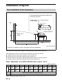
Installation Diagram .........................56
Floor Installation (Front
Projection) .............................56
Ceiling Installation (Front
Projection) .............................58
Index ................................................62
Precautions
maximum protection, repack your unit as it
was originally packed at the factory.
Cleaning the lens
On safety
• Check that the operating voltage of your
unit is identical with the voltage of your
local power supply.
• Should any liquid or solid object fall into
the cabinet, unplug the unit and have it
checked by qualified personnel before
operating it further.
• Unplug the unit from the wall outlet if it is
not to be used for several days.
• To disconnect the cord, pull it out by the
plug. Never pull the cord itself.
• The wall outlet should be near the unit and
easily accessible.
• The unit is not disconnected to the AC
power source (mains) as long as it is
connected to the wall outlet, even if the
unit itself has been turned off.
• Do not look into the lens while the lamp is
on.
• Do not place your hand or objects near the
ventilation holes. The air coming out is
hot.
• Be careful not to get your fingers caught in
the adjuster.
• Do not spread a cloth or paper under the
unit.
On preventing internal heat buildup
After you turn off the power with the ?/1
(On/standby) switch, do not disconnect the
unit from the wall outlet while the cooling
fan is still running.
Caution
The projector is equipped with ventilation
holes (intake) and ventilation holes
(exhaust). Do not block or place anything
near these holes, or internal heat build-up
may occur, causing picture degradation or
damage to the projector.
The lens surface is especially treated to
reduce reflection of light.
As incorrect maintenance may impair the
performance of the projector, take care with
respect to the following:
• Wipe the lens gently with a soft cloth such
as a cleaning cloth or glass cleaning cloth.
• Stubborn stains may be removed with a
soft cloth such as a cleaning cloth or glass
cleaning cloth lightly dampened with
water.
• Never use solvent such as alcohol,
benzene or thinner, or acid, alkaline or
abrasive detergent, or chemical cleaning
cloth, as they will damage the lens surface.
Cleaning the cabinet
• To remove dust from the cabinet, wipe
gently with a soft cloth. If dust is
persistent, wipe with a soft cloth slightly
moistened with a diluted mild detergent
solution.
• Never use any type of abrasive pad,
alkaline/acid cleaner, scouring powder, or
volatile solvent, such as alcohol, benzene,
thinner or insecticide.
• Using such materials or maintaining
prolonged contact with rubber or vinyl
materials may result in damage to the
screen surface and cabinet material.
Black points and bright points (red,
blue, or green) on the screen
The projector is manufactured using highprecision technology.
You may, however, see tiny black points
and/or bright points (red, blue, or green) that
continuously appear on the projector.
This is a normal result of the manufacturing
process and does not indicate a malfunction.
On repacking
Save the original shipping carton and
packing material; they will come in handy if
you ever have to ship your unit. For
5
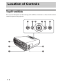
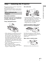
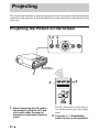
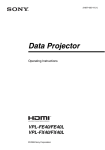
Location of Controls
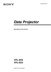
Top/Front/Side
You can use the buttons on the control panel with the same names as those on the remote
control to operate the projector.
4
5 6
7 8
1
6
2
0
3
qa
9
a Ventilation holes (exhaust)
Remove the lens cover before
projection.
c Front remote control detector
d ?/1 (On/standby) switch
Turns on the projector when the
projector is in standby mode. To turn off
the power, press the ?/1 switch twice
according to the message or hold the ?/1
switch for about one second.
The ?/1 (On/standby) indicator lights up
or flashes under the following
conditions:
–Lights in red when the AC power cord
is plugged into a wall outlet. Once the
projector is in standby mode, you can
turn it on with the ?/1 switch.
–Flashes in red when the temperature
becomes high inside the projector, or
when the projector fails to operate.
–Lights in green when the power is
turned on, and when it is ready to
operate.
–Flashes in green until the projector is
ready to operate after the projector is
turned on. Also, flashes in green while
the cooling fan is running after the
power is turned off with the ?/1
switch. The fan runs for about 90
seconds after the power is turned off.
(1 page 27)
–Lights in orange when the power
saving mode is on.
h MENU button
Displays the on-screen menu. Press
again to clear the menu.
i PIC MUTING button
Cuts off the picture. Press again to
restore the picture.
q; Zoom ring
Adjusts the picture size.
qa Focus ring
Adjusts the picture focus.
e INPUT button
Selects an input signal. The input signal
will change whenever you press the
button.
f M/m/</, (arrow) /
buttons
(enter)
Used to enter the settings of items in the
menu system, select a menu, or make
various adjustments.
g LAMP/COVER indicators
Flashes in orange under the following
conditions:
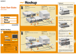
7
Location of Controls
b Lens
• A reception rate of 2 flashes when the
lamp cover or air filter cover is not
secured firmly.
• A reception rate of 3 flashes when the
lamp has reached the end of its life or
reaches a high temperature.
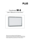
Rear/Bottom
56
7
S VIDEO VIDEO
INPUT A
8
9
0
SERVICE
INPUT
qa
1
8
2
qs
3
qd
4
qf
b Adjusters (fore pad)
c Lamp cover
m Security bar
An anti-theft chain or wire
(commercially available) can be
connected to this bar.
If it is difficult to pull out, pull out the
security bar using a screwdriver.
d Adjuster
Adjusts the picture position. (1 page
23)
e S VIDEO INPUT connector (mini
DIN 4-pin)
Connects to the S video output of video
equipment.
Security bar
f VIDEO INPUT connector (phono
type)
Connects to the video output of video
equipment.
g INPUT A connector (HD D-sub
15-pin, female)
Inputs a computer signal, video GBR
signal, component signal, or DTV signal
depending on the connected equipment.
Connects to the output connector of
equipment using the supplied cable or an
optional cable.
qf Security lock
Connects to an optional security cable
(from Kensington).
Web page address:
http://www.kensington.com/
Note
To maintain optimal performance, clean the
air filter whenever you replace the lamp. (1
page 51)
h Rear remote control detector
i HDMI connector
Connects to the video output connector
of the video equipment or the computer
equipped with HDMI/DVI output
connector (digital).
j SERVICE RS-232C connector
(D-sub 9-pin, female)
Used for service only.
This is not for customers’ use.
k AC IN socket
Connects the supplied AC power cord.
l Adjuster adjustment button
Press to pull out the adjuster. (1 page
23)
9
Location of Controls
a Ventilation holes (intake)/Air
filter cover
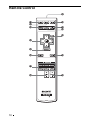
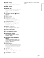
Remote Control
9
1
2
3
0
qa
qs
qd
4
5
6
qf
7
8
10
qg
a LIGHT button
Adjusts the white area of pictures (white
level).
b INPUT button
c FREEZE key
Freezes the projected picture. To cancel
the frozen picture, press the button
again.
d M/m/</, (arrow)/
buttons
(enter)
e MENU button
f WIDE MODE button
Changes the wide screen modes
according to the video signal received.
g PICTURE MODE buttons
Selects the picture viewing mode that
best suits the type of picture or the
environment.
h BRIGHT +/– button
Adjusts the brightness of the picture.
i Infrared transmitter
j ?/1 (On/standby) switch
k PIC MUTING button
Cuts off the picture. Press again to
restore the picture.
l APA (Auto Pixel Alignment)
button
Automatically adjusts a picture to its
clearest while a signal is input from a
computer. (1 page 39)
m RESET button
Resets the value of an item to its factory
preset value. This button functions when
the menu or a setting item is displayed
on the screen.
n ADJ PIC button
Adjusts the picture quality by selecting
the adjustment items.
o CONTRAST +/– button
11
Location of Controls
Illuminates the buttons on the remote
control.
Connections and Preparations
This section describes how to install the projector and screen, how to connect the
equipment from which you want to project the picture, etc.
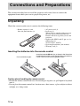
Unpacking
Check the carton to make sure it contains the following items:
• Remote control (1) and
Size AA (R6) batteries (2)
• AC power cord (1)
• Lens cap (1)
When you have purchased the projector,
the lens cap was fitted onto the lens.
Remove this lens cap when you use the
projector.
• Signal cable (HD D-sub 15-pin y 3 ×
phono plug) (1)
(9-885-125-47, SONY)
• Operating Instructions (this manual)
• Warranty card (1)
Inserting the batteries into the remote control
Push and slide to open.
Insert the batteries E side first as shown in the illustration.
Inserting them forcibly or with the polarities reversed may
cause a short circuit and may generate heat.
Caution about handling the remote control
• Handle the remote control with care. Do not drop or step on it, or spill liquid of any kind
onto it.
• Do not place the remote control in a location near a heat source, a place subject to direct
sunlight, or a damp room.
12
Step 1: Installing the Projector
Hot and humid
Before Setting Up the
Projector
Unsuitable installation
Do not place the projector in the following
situations, which may cause malfunction
or damage to the projector.
Poorly ventilated location
• Avoid installing the unit in a location
where the temperature or humidity is very
high, or the temperature is very low.
• To avoid moisture condensation, do not
install the unit in a location where the
temperature may rise rapidly.
Locations subject to direct cool or
warm air from an air-conditioner
• Allow adequate air circulation to prevent
internal heat build-up. Do not place the
unit on surfaces (rugs, blankets, etc.) or
near materials (curtains, draperies) that
may block the ventilation holes. When
internal heat builds up due to blockage of
ventilation holes, the temperature sensor
will function, and the power will be turned
off automatically.
• Leave space of more than 30 cm (11 7/8
inches) around the unit.
• Be careful not to allow the ventilation
holes to inhale tiny objects such as pieces
of paper or clumps of dust.
Installing the projector in such a location
may cause a malfunction of the unit due to
moisture condensation or rise in
temperature.
Near a heat or smoke sensor
Malfunction of the sensor may occur.
13
Connections and Preparations
The projector displays pictures output from
a VCR or other devices.
The projector can be used in various places
and you can enjoy viewing beautiful pictures
easily.
Very dusty and extremely smoky
locations
Avoid installing the unit in a very dusty or
extremely smoky environment. Otherwise,
the air filter will become obstructed, and this
may cause a malfunction of the unit or
damage it. Dust preventing the air passing
through the filter may cause a rise in the
internal temperature of the unit. Clean the
air filter whenever you replace the lamp.
Do not block the ventilation holes
Avoid using a thick-piled carpet or anything
that covers the ventilation holes (exhaust/
intake); otherwise, internal heat may build
up.
Do not place a blocking object just in
front of the lens
Unsuitable conditions
Do not use the projector under the
following conditions.
Do not stand the unit upright on one
side
Avoid using the unit standing upright on its
side. It may cause malfunction.
Do not place any object just in front of the
lens that may block the light during
projection. Heat from the light may damage
the object. Use the PIC MUTING button to
cut off the picture.
Do not use the security bar for
transporting or installation
Do not tilt the unit to the right or left
Avoid tilting the unit to an angle of 15°, and
avoid installing the unit in any way other
than placing it on a level surface or
suspending from the ceiling. Such an
installation may cause color shading or
shorten the lamp life excessively.
14
Use the Security bar at the rear of the
projector for a purpose of preventing theft,
by attaching a commercially available theft
prevention cable for example. If you lift the
projector by holding the Security bar, or
hang the projector by using this bar, it may
cause the projector to fall or be damaged.
Usage at high altitude
When using the projector at an altitude of
1,500 m or higher, turn on “High
Altitude Mode” in the INSTALL SETTING
menu. Failing to set this mode when using
the projector at high altitudes could have
adverse effects, such as reducing
the reliability of certain components.
Connections and Preparations
15
Positioning the Projector and a Screen
The installation distance between the projector and a screen varies depending on the size
of the screen.
1
Determine the installation position of the projector and screen.
Side view
Screen
Distance between the screen and
the center of the lens
* Adjuster not stretched, and the V Keystone function has been done.
When “Wide Mode” in the INPUT SETTING menu is set to “Full 2”
Unit: m (feet)
Projected image size
(diagonal) (inches)
40
80
100
150
200
250
300
Minimum Distance
1.2
(3.9)
2.5
(8.2)
3.1
(10.2)
4.6
(15.1)
6.2
(20.3)
7.7
(25.3)
9.3
(30.5)
Maximum Distance
1.5
(4.9)
2.9
(9.5)
3.7
(12.1)
5.6
(18.4)
7.4
(24.3)
9.3
(30.5)
11.1
(36.4)
There may be a slight difference between the actual value and the design value shown in
the table above.
Notes on Wide Mode settings
• When “Wide Mode” in the INPUT SETTING menu is set to the mode other than “Full 2”, black
bands may appear at the top and bottom or right and left of the screen.
• When “Wide Mode” in the INPUT SETTING menu is set to “4:3”, the projected image size
(diagonal) will be approximately 88 % of “Full 2” size.
• When “Wide Mode” in the INPUT SETTING menu is set to “16:9”, the projected image size
(diagonal) will be approximately 97 % of “Full 2” size.
For details on installation, see “Installation Diagram” on page 56.
16
2
Position the projector so that the lens is parallel to the screen.
Top view
Connections and Preparations
Screen
Note
When using a screen with an uneven surface, stripes pattern may rarely appear on the screen
depending on the distance between the screen and the projector or the zooming magnifications. This
is not a malfunction of the projector.
17
Step 2: Connecting the Projector
When making connections, be sure to do the following:
• Turn off all equipments before making any connections.
• Use the proper cables for each connection.
• Insert the cable plugs properly; poor connection at the plugs may cause a malfunction or
poor picture quality. When pulling out a cable, be sure to pull it out with holding the
plug, not the cable itself.
• Refer to the operating instructions of the connected equipment.
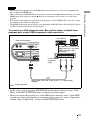
Connecting to a VCR
To connect to a DVD player/recorder and Blu-ray Disc player equipped with
HDMI output
You can enjoy better picture quality by connecting a DVD player/recorder and Blu-ray
Disc player equipped with HDMI output to the HDMI input of the projector.
AV amplifier
Speakers
Rear of the projector
UT A
DVD player/recorder and
Blu-ray Disc player, etc.,
with the HDMI output
SERVICE
INPUT
to HDMI output
HDMI cable (not supplied)
: Video signal flow
When using an optional HDMI cable, be sure to use
a cable that has acquired an HDMI logo.
............................................................................................................................................................
This projector supports PC Display input of HDMI. It also supports HDCP.
18
Notes
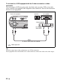
To connect to a DVD player/recorder, Blu-ray Disc player or digital tuner
equipped with a video GBR/component video connectors
Speakers
AV amplifier
Rear of the projector
S VIDEO VIDEO
INPUT A
INPUT
DVD player/recorder, HDD
recorder, Blu-ray Disc player,
digital tuner, etc., with video
GBR/component video
connectors
to video GBR or
component
output
Signal cable (HD D-sub 15-pin (male) y 3 × phono plug)
(supplid)
: Video signal flow
• Set the aspect ratio by pressing WIDE MODE on the remote control or using “Wide
Mode” in the INPUT SETTING menu according to the input signal.
• When you connect the projector to a video GBR output connector, select “Video GBR”
or when you connect the projector to component output connectors, select “Component”
with the “Input-A Signal Sel.” setting in the SET SETTING menu.
19
Connections and Preparations
• When connecting equipment to the HDMI input of the projector, be sure to use equipment that
have acquired the HDMI logo.
• When connecting an HDMI cable to the projector, make sure the v mark on the lower part of the
HDMI input of the projector and the v mark on the connector of the cable is set at the same
position.
• If the picture from equipment connected to the projector with an HDMI cable is not clear, check
the settings of the connected equipment.
• The HDMI connector of this projector is not compatible with DSD (Direct Stream Digital) Signal
or CEC (Consumer Electronics control) Signal.
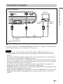
To connect to a VCR equipped with the S video connector or video
connector
You can connect a DVD player/recorder, hard disk video recorder, VCR or laser disk
player, which is not equipped with component video connectors. See also the instruction
manual of each equipment.
Speakers
Rear of the projector
S VIDEO VIDEO
AV amplifier
INPUT A
INPUT
Video equipment
to S video or
video output
S video or video cable (not supplied)
: Video signal flow
Tip
In order to enjoy better video performance, use S Video connector.
If the equipment to be connected has no S video connector, connect the cable to the video output.
20
Connecting to a Computer
Connections and Preparations
Rear of the projector
Computer
INPUT A
SERVICE
INPUT
to monitor
output
to DVI-D
output
HD D-sub15-pin cable (not supplied) or HDMI-DVI-D cable
(not supplied)
: Video signal flow
Tip
Set “Input-A Signal Sel.” in the SET SETTING menu to “Auto” or “Computer.” If the input signal
does not appear properly, set it to “Computer.” (1 page 39)
Notes
• The projector accepts VGA, SVGA, XGA, SXGA, SXGA+, WXGA signals. However, we
recommend that you set the output mode of your computer to WXGA mode for the external
monitor.
• To connect a Macintosh computer equipped with a video output connector of a type having two
rows of pins, use a commercially available plug adaptor.
• If you set your computer, such as a notebook type, to output the signal to both computer’s display
and the external monitor, the picture of the monitor may not appear properly. Set your computer
to output the signal only to the external monitor.
For details, refer to the computer’s operating instructions supplied with your computer. For
settings of the computer, consult with the manufacturer of the computer.
• The HDMI connector of this projector is not compatible with DSD (Direct Stream Digital) Signal
or CEC (Consumer Electronics control) Signal.
• When connecting an HDMI cable to the projector, make sure the v mark on the lower part of the
HDMI input of the projector and the v mark on the connector of the cable is set at the same
position.
21
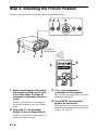
Step 3: Adjusting the Picture Position
Project an image on the screen and adjust the picture position.
1,2 4
6
Rear remote
control detector
8 7
1
5
4
2
6
1
After connecting the AC cord to
the projector, plug the AC cord
into a wall outlet, connect all
equipment, and remove the lens
cover.
The ?/1 (On/standby) switch lights in
red and the projector goes into standby
mode.
2
Press the ?/1 (On/standby)
switch to turn on the projector.
The ?/1 (On/standby) switch flashes in
green, then lights in green.
22
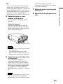
3
Turn on the equipment
connected to the projector.
Refer to the operating instructions of the
connected equipment.
4
Press INPUT to project the
picture on the screen.
Each time you press the button, the input
indication and equipment to be projected
change. (1 page 27)
5
adjusted depending on the room
temperature or the tilt of the screen. In this
case, adjust it manually.
7
Adjust the picture size using the
zoom lever.
8
Adjust the focus using the focus
ring.
Adjust the upper or lower
position of the picture.
Use the adjuster to adjust the picture
position.
Using the adjuster
Lift the projector while pressing the
adjuster adjustment button, and adjust
the tilt of the projector, then release the
button to lock the adjuster.
Adjuster adjustment button
Notes
• Be careful not to let the projector down
on your fingers.
• Do not push hard on the top of the
projector or do not drag it hard with the
adjuster out. It may cause malfunction.
6
Adjust the trapezoidal distortion
of the picture.
The V Keystone adjustment is
performed automatically when you
adjust the tilt of the projector with the
adjuster. If you do not want to perform
the keystone adjustment automatically,
set “V Keystone” in the INSTALL
SETTING menu to “Manual.” (1 page
42)
Note
If you set “V Keystone” to “Auto,” the V
Keystone correction is automatically
adjusted. However, it may not be perfectly
23
Connections and Preparations
Tips
• You can select the desired language for the
menu screen. For details, refer to “Step 4:
Selecting the Menu Language”. (1 page 24)
• When “Auto Input Search” is set to “On” in
the SET SETTING menu, the input terminal
with effective signals is automatically
displayed by pressing INPUT. (1 page 39)
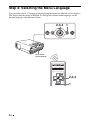
Step 4: Selecting the Menu Language
You can select one of 17 languages for displaying the menu and other on-screen displays.
The factory default setting is English. To change the current menu language, set the
desired language with the menu screen.
2,3,4 1
Rear remote
control detector
2,3,4
1
24
1
Press MENU.
The menu appears.
The menu currently selected is shown as
a yellow button.
Connections and Preparations
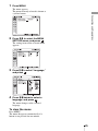
2
Press M/m to select the MENU
SETTING menu, and press
.
The setting items of the selected menu
appears.
3
Press M/m to select “Language,”
and press
.
4
Press M/m/</, to select a
language, and press
.
The menu changes to the selected
language.
To clear the menu
Press MENU.
The menu disappears automatically if a
button is not pressed for one minute.
25
Projecting
This section describes how to operate the projector to view the picture from the equipment
connected to the projector. It also describes how to adjust the quality of the picture to suit
your taste.
Projecting the Picture on the Screen
1,2 4
Rear remote
control detector
1
2
4
1
26
After connecting the AC cord to
the projector, plug the AC cord
into a wall outlet, connect all
equipment, and remove the lens
cover.
The ?/1 (On/standby) switch lights in
red and the projector goes into standby
mode.
2
Press the ?/1 (On/standby)
switch to turn on the projector.
The ?/1 (On/standby) switch flashes in
green, then lights in green.
The projector cannot be used while the
?/1 switch is flashing.
3
changing your computer’s settings.
The key used for switching the computer
to output to the projector varies
depending on the type of computer
Turn on the equipment
connected to the projector.
F7
4
Input-A t
HDMI t Video t S-Video
Fn
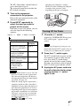
Turning Off the Power
1
To view the picture from Press INPUT
to display
The message disappears if you press any
button other than the ?/1 switch, or if you
do not press any button for five seconds.
HDMI
2
S-Video
Notes
• If “Auto Input Search” is set to “On,” the
projector searches for the signals from
the connected equipment and displays
the input channel where the input signals
are found. (1 page 39)
• When the analog signal is input from a
computer, the Smart APA (Auto Pixel
Alignment) feature adjusts the picture of
the connected equipment to its clearest.
• Depending on the type of your computer,
for example a notebook, or an all-in-one
LCD type, you may have to switch the
computer to output to the projector by
pressing certain keys (e.g.,
LCD / VGA ,
/ , etc.), or by
Press the ?/1 switch again.
The ?/1 switch flashes in green and the
fan continues to run to reduce internal
heat. Also, the ?/1 switch flashes
quickly for the first 60 seconds. During
this time, you will not be able to light up
the ?/1 switch again with this switch.
Video
Video equipment
connected to the VIDEO
INPUT connector
Video equipment
connected to the
S VIDEO INPUT
connector
Press the ?/1 switch.
A message “POWER OFF? Please press
?/1 switch again.” appears on the
screen.
Note
Input-A
Computer/Component
connected to the INPUT
A connector
Computer/VCR, etc.
connected to HDMI
(digital) connector
Fx
and
Press INPUT repeatedly to
select the input you want to
project on the screen.
Each time you press the button, you can
select the input in the following
sequence.
or
Projecting
Refer to the operating instructions of the
connected equipment.
3
Unplug the AC power cord from
the wall outlet after the fan stops
running and the ?/1 switch
lights in red.
27
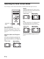
Selecting the Wide Screen Mode
You can enjoy various wide screen modes according to the video signal received.
Normal
A picture with normal 4:3 aspect ratio is
displayed in the center of the screen to fill
the vertical screen size.
Original image
Full
A picture squeezed to 4:3 is displayed with
the correct aspect ratio. A 4:3 picture is
enlarged horizontally to fit the 16:9 screen.
WIDE MODE
button
Press WIDE MODE.
Each time you press the button, you can
change the “Wide Mode” setting in turn.
You can also select it using the menu. (1
page 37)
Wide Zoom (When the SD signal is
input)
A 4:3 aspect ratio picture is enlarged over
the entire screen properly. The upper and
lower portions of the screen are slightly cut
off.
Original image
28
When the Wide
Mode is operated
When the Wide
Mode is operated
Original image
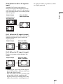
Squeezed
When the Wide
Mode is operated
Tip
Squeezed: An original 16:9 aspect ratio picture
is recorded horizontally compressed to a 4:3
picture.
Zoom (When the SD or PC signal is
input)
A normal 16:9 aspect ratio picture is
enlarged vertically and horizontally in the
same ratio to fill the screen. Use this mode to
view a letterbox picture or a letterbox picture
with side panels.
Letterbox picture
with side panels
Projecting
Original image
the rights of authors or producers, which
are legally protected.
When the Wide
Mode is operated
Letterbox picture
Full 1 (When the PC signal is input)
Displays a picture on the whole of the screen
without changing the aspect ratio of the
original picture.
Original image
When the Wide
Mode is operated
Full 2 (When the PC signal is input)
Displays a picture on the whole of the
screen.
Original image
When the Wide
Mode is operated
Notes
• Changing the aspect ratio of the original
picture will provide a different look from
that of the original image.
• Note that if the projector is used for profit
or for public viewing, modifying the
original picture by switching to the wide
mode may constitute an infringement of
29
Selecting the Picture Viewing Mode
You can select the picture viewing mode that best suits the type of program or room
conditions.
Press one of the PICTURE MODE
buttons (DYNAMIC, STANDARD,
CINEMA and USER 1, USER 2 and
USER 3).
DYNAMIC
The picture becomes bright suitable for
viewing the picture in a bright room.
PICTURE
MODE buttons
DYNAMIC
STANDARD
CINEMA
USER 1,
USER 2 and
USER 3
STANDARD
The quality of the picture becomes more
natural than the one selected by
“DYNAMIC.”
CINEMA
Recommended when viewing a movie in a
dark place.
USER 1, USER 2 and USER 3
You can adjust the quality of the picture to
suit your taste and store the settings into
the selected memory of the projector.
Press one of the USER 1, USER 2 and
USER 3 buttons, then adjust the picture
by using the buttons on the remote control
or the menus. (1 pages 31 and 35)
The settings are stored, and you can view
the picture with the adjusted picture
quality by pressing the button.
30
Adjusting the Picture Quality
You can adjust the picture quality that suits your taste by selecting the adjustment items
with the remote control. The adjusted data can be stored in each picture mode.
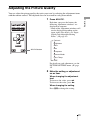
Press ADJ PIC.
Each time you press the button, the
following adjustment windows* are
displayed in sequence.
* Some of the adjustment windows will
not be displayed depending on the
input signal. For details, see “Input
Signals and Adjustable/Setting
Items.” (1 page 45)
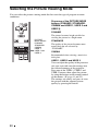
Contrast
Brightness
Color
Hue
ADJ PIC button
Sharpness
Gamma Mode
Color Temp.
DDE
For details on each adjustment, see the
PICTURE SETTING menu. (1 page
35)
2
Make the setting or adjustment
on an item.
When changing the adjustment
level
To increase the value, press ,.
To decrease the value, press <.
When changing the setting
Press M/m to change the setting.
31
Projecting
1
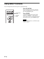
Using Other Functions
You can temporarily turn off or pause a projected picture.
Press PIC MUTING.
Press to temporarily turn off a projected
picture. To return to the previous screen,
press PIC MUTING again.
PIC MUTING
button
FREEZE
button
Press FREEZE.
A projected picture can be paused to be
displayed. “FREEZE” is shown on the
screen when a button is pressed. To return to
the previous screen, press FREEZE again.
Note
The FREEZE function is available for only
computer signal.
32
Using the Menus
This section describes how to make various adjustments and settings using the menus.
Operation through the Menus
Input signal setting indicator
When Input-A is selected: Shows “Auto”
or “Input-A Signal Sel.” setting in the SET
SETTING menu.
When Video or S-Video is selected: Shows
“Auto” or the “Color System” setting in the
SET SETTING menu.
RESET
button
1
The menu window appears.
The menu presently selected is shown as
a yellow button in the column on the left.
2,3,4
SET SETTING
1
S m a r t A PA :
Auto Input Search:
Input-A Signal Sel.:
Color System:
Pow e r S av i n g :
IR Receiver:
Lamp Timer Reset
Display items
The input signal and input signal setting
indicators are displayed on the upper right
corner of the menu window.
Input signal indicator
Input signal setting indicator
Input signal indicator
Shows the selected input channel. x
is
displayed when no signal is input. You can
hide this indicator using “Status” in the
MENU SETTING menu.
Press MENU.
Input-A
On
Off
Component
Au t o
Off
F ro n t & R e a r
2
Press M/m to select a menu, and
press , or
.
The items that can be set or adjusted
with the selected menu appear.
3
Press M/m to select an item you
want to set or adjust and press ,
or
.
The items that can be set appear in the
pop-up menu, adjustment menu, or in
the next menu window.
33
Using the Menus
The projector is equipped with an on-screen menu for making various adjustments and
settings. Some of the adjustable/setting items are displayed in a pop-up menu, in an
adjustment menu with no main menu, or in the next menu window. If you select an item
name followed by dots (···), the next menu window with setting items appears.
To change the on-screen menu language, see “Step 4: Selecting the Menu Language”.
(1 page 24)
To clear the menu
Pop-up menu
Menu
Setting items
MENU SETTING
Input A
Status:
L a n g u ag e :
M e nu Po s i t i o n :
S t a r t U p I m ag e
On
English
To p l e f t
Bottom Left
Center
To p R i g h t
Bottom Right
A
Adjustment menu
Next menu window
Menu
Setting items
PICTURE SETTING
Input A
ADJUST PICTURE
Contrast:
Brightness:
Gamma Mode:
C o l o r Te m p . :
S t a n d a rd
80
50
Off
High
Press MENU.
The menu disappears automatically if a
button is not pressed for one minute.
To reset the items that have been
adjusted
Select an item that you want to reset, then
press RESET on the remote control.
The message “Complete!” appears on the
screen and the setting of the item that you
have selected is reset to its factory preset
value.
Items that can be reset are:
• “Contrast,” “Brightness,” “Color,” “Hue”
and “Sharpness” in the “Adjust Picture...”
menu of the PICTURE SETTING menu
• “Dot Phase,” “H Size,” and “Shift” in the
“Adjust Signal...” menu of the INPUT
SETTING menu
Storage of the settings
The settings are automatically stored in the
projector memory when the
button is
pressed.
If no signal is input
If there is no input signal, the message
“Cannot adjust this item.” appears on the
screen.
4
Make the setting or adjustment of
an item.
When changing the adjustment
level
To increase the value, press M/,.
To decrease the value, press m/<.
Press
to restore the previous screen.
When changing the setting
Press M/m to change the setting.
Press
to restore the previous screen.
You can restore the previous screen
using < depending on the selected
item.
Items that cannot be adjusted
Adjustable items differ depending on the
input signal. The items that cannot be
adjusted or set do not appear in the menu.
(1 page 45)
34
PICTURE SETTING Menu
The PICTURE SETTING menu is used for adjusting the picture.
PICTURE SETTING
Picture Mode
Adjust Picture...
Input A
S t a n d a rd
PICTURE SETTING
Input-A
ADJUST PICTURE
Contrast:
Brightness:
Gamma Mode:
C o l o r Te m p . :
S t a n d a rd
80
50
Off
High
Using the Menus
Setting items
Functions
Initial setting
Picture Mode
You can select the picture viewing mode that best
suits the type of picture or the environment.
Dynamic: Select this for bright picture suitable for
viewing it in a bright room.
Standard: Select this for more natural picture than
the picture with the Dynamic setting.
Cinema: Select this for watching movies, etc. in a
dark environment.
User 1, User 2, User 3: You can adjust the quality of
the picture to suit your taste and then store the
settings. Once the settings are stored, you can view
the picture with the adjusted picture quality by
pressing PICTURE MODE on the remote control.
Set according to
the input signal
To store the settings
1 Select User 1, User 2, or User 3.
2 Adjust the items you want in the menus.
Tips
• You can also adjust the picture quality in
“Dynamic”, “Standard” or “Cinema”, and store the
settings. To reset everything to the factory settings,
select “Picture Mode,” and press RESET on the
remote control.
• Some items may not be displayed in the PICTURE
SETTING menu, depending on the type of input
signal. For details, see “Input Signals and
Adjustable/Setting Items” (1 page 45).
Adjust Picture...
Contrast
The projector can store the setting values of the following menu items for
each picture mode separately.
Adjusts the white area of pictures (white level).
The higher the setting, the greater the contrast. The
lower the setting, the lower the contrast.
You can make adjustments by pressing
CONTRAST+/– on the remote control.
80
35
Setting items
36
Functions
Initial setting
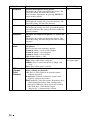
Brightness
Adjusts the brightness of the picture.
The higher the setting, the brighter the picture. The
lower the setting, the darker the picture.
You can make adjustments by pressing BRIGHT+/–
on the remote control.
50
Color
Adjusts the intensity of the color density.
The higher the setting, the greater the intensity. The
lower the setting, the lower the intensity.
50
Hue
Adjusts the color tone.
The higher the setting, the more greenish the picture
becomes. The lower the setting, the more reddish the
picture becomes.
50
Sharpness
Sharpens the outline of the picture, or reduces the
noise.
The higher the setting, the sharper the picture. The
lower the setting, the softer the picture, thus reducing
the noise.
30
Gamma
Mode
Adjusts the response characteristics of the tone of
the picture.
Select a favorite tone from three options.
Gamma1: Makes a scene a little brighter.
Gamma2: Makes a scene brighter.
Gamma3: Makes a scene darker.
Off: Gamma Mode is “Off”.
Off
Color Temp.
Adjusts the color temperature.
High: Gives white colors a blue tint.
Middle: Gives a neutral tint between “High” and
“Low”.
Low: Gives white colors a red tint.
Set according to
the input signal
DDE
(Dynamic
Detail
Enhancer)
According to the film source you have selected,
make a setting for playback.
Off: Plays a video signal in an interlace format
without converting.
Progressive: Converts an interlace format video
signal to a progressive format.
Film: Normally, select this option. Reproduces the 23 Pull-Down film sources with smooth picture
movement. When the video signal with a format
other than the 2-3 Pull-Down is input,
“Progressive” is automatically selected.
Film
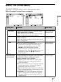
INPUT SETTING Menu
The INPUT SETTING menu is used to adjust the input signal.
When the signal is input from a computer
Setting items
Normal
Off
Using the Menus
Adjust Signal...
Wide Mode:
Over Scan:
Functions
Initial setting
Dot Phase
Adjusts the dot phase of the LCD panel and the
signal output from a computer.
Adjust the picture further for finer picture after the
picture is adjusted by pressing the APA key.
Set according to
the input signal
H Size
Adjusts the horizontal size of a picture output
from a computer.
Adjust the setting according to the dots of the input
signal. (1 page 54)
Set according to
the input signal
Shift
Adjusts the position of the picture.
H: As the setting for H (horizontal) increases, the
picture moves to the right, and as the setting
decreases, the picture moves to the left. Use
</, to adjust the horizontal position.
V: As the setting for V (vertical) increases, the
picture moves up, and as the setting decreases, the
picture moves down. Use M/m to adjust the
vertical position.
Set according to
the input signal
You can set the aspect ratio of the picture to be
displayed for the current input signal. This item is
enabled only when an video signal (preset
memory numbers 1 to 11) is input.
Normal: A picture with normal 4:3 aspect ratio is
displayed in the center of the screen to fill the
vertical screen size.
Full: A picture squeezed to 4:3 is displayed with the
correct aspect ratio. A 4:3 picture is enlarged
horizontally to fit the 16:9 screen.
Zoom: A normal 16:9 aspect ratio picture (SD signal
only) is enlarged vertically and horizontally in the
same ratio to fill the screen.
Wide Zoom: A 4:3 aspect ratio picture (SD signal
only) is enlarged over the entire screen properly.
The upper and lower portions of the screen are
slightly cut off.
Set according to
the input signal
Adjust Signal...
Wide Mode
(When the video
signal is input)
37
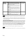
Setting items
Functions
Initial setting
Wide Mode
(When the PC
signal is input)
You can set the aspect ratio of the picture to be
displayed for the current input signal. This item is
enabled only when an PC signal (preset memory
numbers 21 to 63) is input.
Full 1: Displays a picture on the whole of the screen
without changing the aspect ratio of the original
picture.
Full 2: Displays a picture on the whole of the screen.
Normal: Displays the picture while matching one
pixel of input picture element to that of the LCD.
The picture will be clear but the picture size will
be smaller.
Zoom: A normal 16:9 aspect ratio picture is enlarged
vertically and horizontally in the same ratio to fill
the screen.
Set according to
the input signal
Over Scan
Hides the outer edges of the picture.
On: Hides the outer edges of the input picture. Select
this setting when noise appears along the edge of
the picture.
Off: Projects the whole of the input picture.
On
Notes
• Some of the “Wide Mode” setting items are not displayed on the screen according to the input
signal.
• Note that if the projector is used for profit or for public viewing, modifying the original picture by
switching to the wide mode may constitute an infringement of the rights of authors or producers,
which are legally protected.
About the Preset Memory No.
This projector has 45 types of preset data for input signals (the preset memory). When a
preset signal is input, the projector automatically detects the signal type and recalls the
data for the signal from the preset memory to adjust it to an optimum picture. The memory
number and signal type of that signal are displayed on the INFORMATION menu (1
page 44). You can also adjust the preset data through the INPUT SETTING menu.
See the chart on page 54 to find if the signal is registered in the preset memory.
Note
When the aspect ratio of input signal is other than “Full 2”, a part of the screen may be displayed in
black.
38
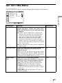
SET SETTING Menu
The SET SETTING menu is used for changing the settings of the projector.
SET SETTING
Input-A
On
Off
Au t o
Au t o
Off
F ro n t & R e a r
Setting items
Functions
Initial setting
Smart APA
The APA (Auto Pixel Alignment) automatically
adjusts “Dot Phase,” “H Size” and “Shift” in the
INPUT SETTING menu for the input signal from
a computer.
On: When a signal is input from a computer, the
APA functions automatically so that the picture
can be seen clearly. Once the specified input
signal has been adjusted by the “Smart APA,” it
will not be readjusted even when the cable is
disconnected and connected again or the input
channel is changed. You can adjust the picture by
pressing APA on the remote control even if “Smart
APA” is set to “On.”
Off: APA functions only when you press APA on the
remote control.
On
Auto Input Search
Detects the input signal and displays the detected
input signal automatically when the INPUT
button is pressed.
When set to “On,” the projector detects input signals
in the following order: Input-A, HDMI, Video and SVideo. It indicates the input channel when the power
is turned on or the INPUT button is pressed.
Off
Input-A Signal
Sel.
Selects the type of signal input from the
equipment connected to the INPUT A connector.
Selects the type of signal input from the equipment
by selecting “Input-A” with the INPUT button.
Auto: Selects the input signal type automatically.
Computer: Inputs the signal from a computer.
Component: Inputs the component signal from a
DVD player/recorder, Blu-ray Disc player, digital
tuner, etc.
Video GBR: Inputs the signal from a TV game or
HDTV broadcast.
Auto
Using the Menus
S m a r t A PA :
Auto Input Search:
Input-A Signal Sel.:
Color System:
Pow e r S av i n g :
IR Receiver:
Lamp Timer Reset
39
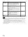
Setting items
Functions
Initial setting
Color System
Selects the color system of the input signal.
If you select “Auto,” the projector detects the color
system of the input signal automatically. If the
picture is distorted or colorless, select the color
system according to the input signal.
Auto
Power Saving
Selects the Power Saving mode.
Lamp off: The lamp goes off if no signal is input for
10 minutes. The lamp lights again when a signal is
input or any button is pressed.
Standby: The projector goes into Standby mode if
no signal is input for 10 minutes. To use it, turn on
the power again.
Off: The projector does not go into Power Saving
mode.
Off
IR Receiver
Selects the remote control detectors (IR Receiver)
on the front and rear of the projector.
Front & Rear: Activates both the front and rear
detectors.
Front: Activates the front detector only.
Rear: Activates the rear detector only.
Front & Rear
Lamp Timer
Reset
When replacing the lamps, reset the lamp timer.
–
Notes
• Press APA when the full image is displayed on the screen. If the projected image includes a black
portion around it, the APA function will not work properly and some parts of the image may not
be displayed on the screen.
- You can cancel the adjustment by pressing APA again while “Adjusting” appears on the screen.
- The picture may not be adjusted properly depending on the type of input signal.
- Adjust the “Dot Phase,” “H Size,” and “Shift” items in the INPUT SETTING menu when you
adjust the picture manually.
• If the input signal is not displayed correctly when “Input-A Signal Sel.” is set to “Auto,” set it to
conform the input signal.
40
MENU SETTING Menu
The MENU SETTING menu is used for changing the menu displays.
Functions
Initial setting
Status (on-screen
display)
Sets whether or not the on-screen display is
displayed.
Set to “Off” to turn off the on-screen displays except
for the menus, message when turning off the power,
and warning messages.
On
Language
Selects the language used in the menu and onscreen displays.
The languages available are: English, Nederlands,
Français, Italiano, Deutsch, Español, Português,
, Svenska, Norsk,
,
,
,
,
,
and
.
English
Menu Position
Selects the display position of the menu.
You can select from “Top Left,” “Bottom Left,”
“Center,” “Top Right,” and “Bottom Right.”
Bottom Left
Start Up Image
Sets whether or not the start-up image is
displayed after the projector is turned off.
On: Displays the Start Up Image in the window after
turning on the power.
Off: Does not display the Start Up Image in the
window after turning on the power.
On
Using the Menus
Setting items
41
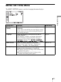
INSTALL SETTING Menu
The INSTALL SETTING menu is used for changing the settings of the projector.
INSTALL SETTING
Input-A
V Key s t o n e :
Au t o
I m ag e F l i p :
Off
B a ck g ro u n d :
Blue
Lamp Mode:
S t a n d a rd
High Altitude Mode: O f f
Setting items
Functions
Initial setting
V Keystone
Corrects the trapezoidal distortion caused by the
projection angle.
Select “Auto” for automatic correction, or “Manual” for
manual correction using the M/m/</, buttons.
When the bottom of the trapezoid is longer than the
top
: Sets a lower value.
When the top of the trapezoid is longer than the
bottom
: Sets a higher value.
Auto
Image Flip
Flips the image on the screen horizontally and/or
vertically.
HV: Flips the image horizontally and vertically.
H: Flips the image horizontally.
V: Flips the image vertically.
Off: The image does not flip.
Off
Background
Selects the background color of the screen when no
signal is input.
Select “Black” or “Blue.” Normally, set to “Blue.”
Blue
Lamp Mode
Sets the lamp brightness used during the projection.
High: Illuminates the projected image brightly.
Standard: Reduces fan noise and power consumption.
The brightness of the projected image will be lower
compared with the “High” setting.
Standard
High Altitude
Mode
Set to “On” when the projector is used at an altitude
of 1,500 m or higher.
Off
42
Notes
• The picture quality may deteriorate when the V Keystone function is used, because it is an
electrical correction.
• If you set “High Altitude Mode” to “On” at an altitude of under 1,500 m, the reliability of the lamp
may be reduced.
• The auto V Keystone adjustment may not correct the trapezoidal distortion perfectly, depending
on the room temperature or the screen angle.
Using the Menus
43
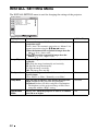
INFORMATION Menu
The INFORMATION menu displays the model name, serial number, the horizontal and
vertical frequencies of the input signal and the cumulated hours of usage of the lamp.
Model name
INFORMATION
VPL-BW5
fH:
fV:
Lamp Timer:
Input A
Serial No. 3 3 3 3 3 3 3
48,47kHz
60,00Hz
No.23
1024x768
2
H
Serial number
Memory number
Signal type
Model name
Displays the model name.
Serial number
Displays the serial number.
fH (horizontal frequency)
Displays the horizontal frequency of the input signal.
fV (vertical frequency)
Displays the vertical frequency of the input signal.
Memory number
Displays the preset memory number of the input signal.
Signal type
Displays the type of the input signal.
Lamp Timer
Indicates how long the lamp has been turned on (total usage).
Notes
• fH (horizontal frequency) and fV(vertical frequency) may not be displayed depending on the input
signal used on the projector.
• You cannot change any items listed above.
44
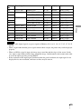
Input Signals and Adjustable/Setting Items
Some of the items in the menus cannot be adjusted depending on the input signal as
indicated in the following tables. The items that cannot be adjusted are not displayed in
the menu.
PICTURE SETTING menu
Input signal
Item
Component
Video GBR
Computer
HDMI
z
z
z
z
z
Using the Menus
Picture Mode
Video or SVideo (Y/C)
Adjust Picture...
Contrast
z
z
z
z
z
Brightness
z
z
z
z
z
Color
z
z
z
–
z
Hue
z
z
z
–
–
(NTSC 3.58/
4.43 only)
Sharpness
z
z
z
–
z
Gamma
Mode
z
z
z
z
z
Color Temp.
z*2
z*2
z*2
z*2
DDE
z
z
–
z
(Interlace
format only)*1
(Interlace
format
only)*1
z*2
z
(Interlace
format
only)*1
z : Adjustable/can be set
– : Not adjustable/cannot be set
*1: Except for preset memory No. 7, 8
*2
: Cannot be set in the Dynamic mode
INPUT SETTING menu
Input signal
Item
Video/S-Video
(Y/C)
Component
Video GBR
Computer
HDMI
z
z
z
z*3
z
Dot Phase
–
–
–
z
–
H size
–
–
–
z
–
Shift
–
z
z
z
–
–
z
z
–
z
Wide Mode
Adjust Signal...
Over Scan
z : Adjustable/can be set
– : Not adjustable/cannot be set
*3
: Can be set except preset memory number 49.
45
Others
This section describes how to solve the problems, how to replace the lamp and air filter,
etc.
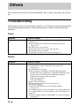
Troubleshooting
If the projector appears to be operating erratically, try to diagnose and correct the problem
using the following instructions. If the problem persists, consult with qualified Sony
personnel.
Power
Symptom
Cause and Remedy
The power is not turned
on.
• The power has been turned off and on with the ?/1 switch at a
short interval.
c Wait for about 90 seconds before turning on the power
(1 page 27).
• The lamp cover is not secured.
c Close the lamp cover securely (1 page 49).
• The air filter cover is detached.
c Attach the air filter cover securely (1 page 51).
Picture
Symptom
Cause and Remedy
No picture.
• A cable is disconnected or the connections are wrong.
c Check that the proper connections have been made
(1 page 18).
• The connections are wrong.
c This projector is compatible with DDC2B (Digital Data
Channel 2B). If your computer is compatible with DDC, turn
the projector on according to the following procedures.
1 Connect the projector to the computer.
2 Turn the projector on.
3 Start the computer.
• Input selection is incorrect.
c Select the input source correctly (1 page 27).
• The picture is muted.
c Press PIC MUTING to release the picture muting
(1 page 32).
• The computer signal is not set to output to an external monitor or
set to output both to an external monitor and a LCD monitor of a
computer.
c Set the computer signal to output only to an external monitor
(1 page 21).
46
Cause and Remedy
Noise may appear on the background depending on the
combination of the number of dots input from the computer and
the numbers of pixels on the LCD panel.
c Change the desktop pattern on the connected computer.
The picture from the
INPUT A connector is
colored strange.
The input signal cannot be received at “Auto” of “Input-A Signal
Sel” in the SET SETTING menu, or the setting of “Input-A Signal
Sel” is incorrect.
c Selects “Computer”, “Video GBR” or “Component” correctly
according to the input signal (1 page 39).
On-screen display does
not appear.
“Status” in the MENU SETTING menu has been set to “Off.”
c Set “Status” in the MENU SETTING menu to “On”
(1 page 41).
Color balance is
incorrect.
• The picture has not been adjusted properly.
c Adjust the picture (1 page 31).
• The projector is set to the wrong color system.
c Set “Color System” in the SET SETTING menu to match the
color system being input (1 page 40).
The picture is too dark.
• Contrast or brightness has not been adjusted properly.
c Adjust the contrast or brightness in the “Adjust Picture...”
menu properly (1 page 35).
• The lamp has burnt out or is dim.
c Replace the lamp with a new one (1 page 49).
The picture is not clear.
• The picture is out of focus.
c Adjust the focus using the focus ring (1 page 23).
• Condensation has accumulated on the lens.
c Leave the projector for about two hours with the power on.
The image extends
beyond the screen.
• The APA button has been pressed even though there are black
edges around the image.
c Display the full image on the screen and press APA.
c Adjust “Shift” in the INPUT SETTING menu properly
(1 page 37).
• The input signal cannot be projected as the frequency is out of
the acceptable range of the projector.
c Input a signal that is within the range of the frequency.
• The resolution setting of the output signal of the computer is too
high.
c Set the output setting to WXGA (1 page 21).
The picture flickers.
“Dot Phase” in the INPUT SETTING menu has not been adjusted
properly.
c Adjust “Dot Phase” in the INPUT SETTING menu properly
(1 page 37).
Remote control
Symptom
Cause and Remedy
The remote control does
not work.
Batteries are dead.
c Replace them with new batteries (1 page 12).
47
Others
Symptom
The picture is noisy.
Indicators
Symptom
Cause and Remedy
The LAMP/COVER
indicator flashes in
orange. (Repetition rate
of 2 flashes)
• The lamp cover or the air filter cover is detached.
c Attach the cover securely (1 pages 49 and 51).
The LAMP/COVER
indicator flashes in
orange. (Repetition rate
of 3 flashes)
• The lamp has reached the end of its life.
c Replace the lamp (1 page 49).
• The lamp has reached a high temperature.
c Wait for 60 seconds until the lamp cools, then turn on the
power again.
:/1 switch flashes in
red. (Repetition rate of 2
flashes)
• The internal temperature is unusually high.
c Check to ensure that nothing is blocking the ventilation holes.
• The projector is being used at a high altitude.
c Ensure that “High Altitude Mode” in the INSTALL SETTING
menu is set to “On.”
:/1 switch flashes in
red. (Repetition rate of 4
flashes)
The fan is broken.
c Consult with qualified Sony personnel.
:/1 switch flashes in
red. (Repetition rate of 6
flashes)
Unplug the AC power cord from the wall outlet after the :/1
switch stops flashing, plug the power cord to the wall outlet, then
turn the projector on again. If the :/1 switch flashes in red and the
problem persists, the electrical system has failed.
c Consult with qualified Sony personnel.
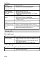
Message Lists
Warning Message
Message
Meaning and Remedy
Please replace the Lamp
and clean the Filter.
• It is time to replace the lamp and clean the air filter.
c Replace the lamp (1 page 49) and clean the filter (1 page
51).
• When this message appears even after replacing the lamp, the
task has not been completed.
c Perform the operation of steps 10 to 13 on page 50.
Caution Message
Message
Meaning and Remedy
Not applicable!
You have pressed the wrong button.
c Press the appropriate button.
48
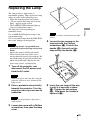
Replacing the Lamp
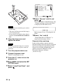
Note
For safety reasons, do not loosen any other
screws.
4
Notes
• If the lamp breaks, ask qualified Sony
personnel to replace the lamp and to check
inside.
• Pull out the lamp by holding the handle.
• When removing the lamp, make sure it
remains horizontal, then pull straight up. Do
not tilt the lamp. If you pull out the lamp
while tilted and if the lamp breaks, the
pieces may scatter, causing injury.
1
Loosen the two screws on the
lamp unit with the Phillips
screwdriver (a). Fold out the
handle (b), then pull out the
lamp unit by the handle (c).
Handle
Turn off the projector, and
disconnect the AC power cord
from the AC outlet.
Note
When you replace the lamp after using the
projector, wait for at least an hour for the
lamp to cool.
2
Place a protective sheet (cloth)
beneath the projector. Turn the
projector over so you can see its
underside.
5
Insert the new lamp all the way
in until it is securely in place
(a). Tighten the two screws
(b). Fold down the handle to
replace it (c).
Note
Be sure that the projector is placed on a
stable surface.
3
Loosen the screw with a Phillips
screwdriver, then open the lamp
cover.
49
Others
The lamp used as a light source is
consumable product. Thus replace the lamp
with a new one in the following cases.
• When the lamp has burnt out or dims
• “Please replace the Lamp and clean the
Filter” appears on the screen
• The LAMP/COVER indicator lights up
(repeats flashing three times)
The lamp life varies depending on
conditions of use.
Use an LMP-E190 Projector Lamp as the
replacement lamp.
Use of any other lamps than the LMP-E190
may cause damage to the projector.
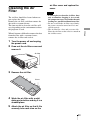
SET SETTING
Input-A
S m a r t A PA :
Auto Input Search:
Input-A Signal Sel.:
Color System:
Pow e r S av i n g :
IR Receiver:
Lamp Timer Reset
On
Off
Au t o
Au t o
Off
F ro n t & R e a r
12 Select “Execute” with m, and
press
.
The Lamp Timer is initialized to 0, and
“Change the Lamp and clean the Filter?”
is displayed in the menu screen.
Notes
• Be careful not to touch the glass surface
of the lamp.
• The power will not turn on if the lamp is
not secured properly.
• Do not allow any liquid or other objects
into the slot to avoid electrical shock or
fire.
6
Close the lamp cover and
tighten the screw.
Note
Be sure to attach the lamp cover securely
as it was. If not, the projector cannot be
turned on.
7
8
Turn the projector back over.
Connect the power cord.
The ?/1 switch lights in red.
9
Press the ?/1 switch to turn the
projector on.
10Press MENU, and select the SET
SETTING menu.
11Select “Lamp Timer Reset”, and
press
50
.
Change the Lamp and clean the Filter?
Yes:
No:
Refer to page 51 for “Cleaning the Air
Filter”.
13 Select “Yes” with M.
“Lamp Timer Reset Complete!” is
displayed in the menu screen.
Disposal of the used lamp
Lamp in this product contains mercury.
Disposal of these materials may be regulated
due to environmental considerations. For
disposal or recycling information, please
contact your local authorities or the
Electronic Industries Alliance
(www.eiae.org).
air filter cover and replace the
cover.
Cleaning the Air
Filter
Notes
The air filter should be cleaned whenever
you replace the lamp.
Remove the air filter, and then remove the
dust with a vacuum cleaner.
The time needed to clean the air filter will
vary depending on the environment or how
the projector is used.
1
Turn the power off and unplug
the power cord.
2
Draw out the air filter cover and
remove it.
Air filter
3
Remove the air filter.
Claws
4
Wash the air filter with a mild
detergent solution and dry it in a
shaded place.
5
Attach the air filter so that it fits
securely into each claw on the
51
Others
When it becomes difficult to remove the dust
from the filter with a vacuum cleaner,
remove the air filter and wash it.
• If you neglect to clean the air filter, dust
may accumulate, clogging it. As a result,
the temperature may rise inside the unit,
leading to a possible malfunction or fire.
• Be sure to attach the air filter cover firmly;
the power can not be turned on if it is not
closed securely.
• The air filter has a face and a reverse side.
Place the air filter so that it fits in a notch on
the air filter cover.
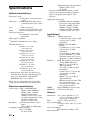
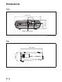
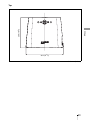
Specifications
Optical characteristics
Projection system
3 LCD panels, 1 lens, projection
system
LCD panel
0.59-inchvWXGA panel, about
3,070,000 pixels (1280 × 800 ×
3)
Lens
1.2 times zoom lens
f 18.53 to 22.18 mm/F1.65 to 1.93
Lamp
190 W Ultra high pressure lamp
Projected picture size
40 to 300 inches (measured
diagonally)
Light output1) 2000 lm
1)
Applicable video signals
15 k RGB/component 50/60 Hz,
Progressive component 50/60
Hz, DTV (480/60i, 575/50i,
480/60p, 575/50p, 720/60p,
720/50p, 1080/60i, 1080/50i),
Composite video, Y/C video
Input/Output
VIDEO IN
When the Lamp Mode is set to “High.”
Throwing distance 2)
40-inch: 1.2 to 1.5 m
(3.9 to 4.9 feet)
80-inch: 2.5 to 2.9 m
(8.2 to 9.5 feet)
100-inch: 3.1 to 3.7 m
(10.2 to 12.1 feet)
150-inch: 4.6 to 5.6 m
(15.1 to 18.4 feet)
200-inch: 6.2 to 7.4 m
(20.3 to 24.3 feet)
250-inch: 7.7 to 9.3 m
(25.3 to 30.5 feet)
300-inch: 9.3 to 11.1 m
(30.5 to 36.4 feet)
2)
(Maximum input signal resolution:
SXGA+ 1400 × 1050
fV: 60 Hz)
3) Set the resolution and the frequency of the
signal of the connected computer within the
range of acceptable preset signals of the
projector.
INPUT A
When placed on the floor, the adjuster not
stretched, the V Keystone function has been
done, and “Wide Mode” in the INPUT
SETTING menu is set to “Full 2.”
There may be a slight difference between the
actual value and the design value shown above.
Electrical characteristics
Color system NTSC3.58/PAL/SECAM/
NTSC4.43/PAL-M/PAL-N/
PAL60 system, switched
automatically/manually
(NTSC4.43 is the color system
used when playing back a video
recorded in NTSC on a
NTSC4.43 system VCR.)
Resolution
750 horizontal TV lines (video
input)
1280 × 800 dots (RGB input)
Acceptable computer signals3)
fH: 19 to 92 kHz
fV: 48 to 92 Hz
52
HDMI
SERVICE
VIDEO: phono type
Composite video: 1 Vp-p ±2 dB
sync negative (75 ohms
terminated)
S VIDEO: Y/C mini DIN 4pintype
Y (luminance): 1 Vp-p ±2 dB
sync negative (75 ohms
terminated)
C (chrominance): burst 0.286
Vp-p ±2 dB (NTSC) (75 ohms
terminated), burst 0.3 Vp-p ±2
dB (PAL) (75 ohms terminated)
RGB: HD D-sub15-pin (female)
Analog RGB/component:
R/R-Y: 0.7 Vp-p ±2 dB (75
ohms terminated)
G: 0.7 Vp-p ±2 dB (75 ohms
terminated)
G with sync/Y: 1 Vp-p ±2 dB
sync negative (75 ohms
terminated)
B/B-Y: 0.7 Vp-p ±2 dB (75
ohms terminated)
HD: Horizontal sync input: TTL
level, positive/negative
VD: Vertical sync input: TTL
level, positive/negative
Digital RGB/Y CB (PB) CR (PR)
RS-232C: D-sub 9 pin
General
314 × 109 × 269 mm (12 3/8 ×
4 3/8 × 10 5/8 inches) (w/h/d)
(without projecting parts)
Mass
Approx. 3.0 kg (6 lb 10 oz)
Power requirements
AC 100 to 240 V, 2.6 to 1.1 A, 50/
60 Hz
Power consumption
Max.260 W (in standby: 3 W)
Heat dissipation
Dimensions
Others
884 BTU
Operating temperature
0°C to 35°C (32°F to 95°F)
Operating humidity
35% to 85% (no condensation)
Storage temperature
–20°C to +60°C (–4°F to +140°F)
Storage humidity
10% to 90%
Supplied accessories
Remote control (1)
Size AA (R6) batteries (2)
Signal cable (HD D-sub 15-pin
y 3 × phono plug) (1)
(9-885-125-47, SONY)
AC power cord (1)
Lens cap (1)
Operating Instructions (1)
Warranty card (1)
Design and specifications are subject to change
without notice.
Optional accessory
Projector Lamp
LMP-E190 (for replacement)
Some of the items may not be available in
some areas. For details, please consult your
nearest Sony dealer.
Pin assignment
INPUT A connector (HD D-sub 15-pin,
female)
1
R/R-Y
9
2
3
4
5
6
7
8
G/Y
B/B-Y
RESERVE
GND
GND (R)
GND (G)
GND (B)
10
11
12
13
14
15
Power
supply input
for DDC
GND
GND
DDC/SDA
HD
VD
DDC/SCL
53
Preset Signals
Memory Preset signal
No.
fH (kHz)
fV (Hz)
Sync
1
Video 60 Hz
60 Hz
15.734
59.940
–
2
Video 50 Hz
50 Hz
15.625
50.000
–
3
480/60i
480/60i
15.734
59.940
S on G/Y
4
575/50i
575/50i
15.625
50.000
S on G/Y
5
480/60p
480/60p (Progressive
component NTSC)
31.470
60.000
S on G/Y
6
575/50p
575/50p (Progressive
component PAL)
31.250
50.000
S on G/Y
7
1080/60i
1035/60i, 1080/60i
33.750
60.000
S on G/Y
8
1080/50i
1080/50i
28.130
50.000
S on G/Y
10
720/60p
720/60p
45.000
60.000
S on G/Y
11
720/50p
720/50p
37.500
50.000
S on G/Y
21
640 × 350
VGA mode 1
31.469
70.086
H-pos, V-neg
22
23
640 × 400
VGA VESA 85 Hz
37.861
85.080
H-pos, V-neg
PC-9801 Normal
24.823
56.416
H-neg, V-neg
24
VGA mode 2
31.469
70.086
H-neg, V-pos
25
VGA VESA 85 Hz
37.861
85.080
H-neg, V-pos
26
640 × 480
VGA mode 3
31.469
59.940
H-neg, V-neg
27
Macintosh 13"
35.000
66.667
H-neg, V-neg
28
VGA VESA 72 Hz
37.861
72.809
H-neg, V-neg
29
VGA VESA 75 Hz
37.500
75.000
H-neg V-neg
30
VGA VESA 85 Hz
43.269
85.008
H-neg V-neg
SVGA VESA 56 Hz
35.156
56.250
H-pos, V-pos
32
SVGA VESA 60 Hz
37.879
60.317
H-pos, V-pos
33
SVGA VESA 72 Hz
48.077
72.188
H-pos, V-pos
34
SVGA VESA 75 Hz
46.875
75.000
H-pos, V-pos
35
SVGA VESA 85 Hz
53.674
85.061
H-pos, V-pos
31
800 × 600
36
832 × 624
Macintosh 16"
49.724
74.550
H-neg, V-neg
37
1024 × 768
XGA VESA 60 Hz
48.363
60.004
H-neg, V-neg
38
XGA VESA 70 Hz
56.476
70.069
H-neg, V-neg
39
XGA VESA 75 Hz
60.023
75.029
H-pos, V-pos
40
XGA VESA 85 Hz
68.677
84.997
H-pos, V-pos
SXGA VESA 70 Hz
63.995
70.019
H-pos, V-pos
42
SXGA VESA 75 Hz
67.500
75.000
H-pos, V-pos
43
SXGA VESA 85 Hz
77.487
85.057
H-pos, V-pos
41
54
1152 × 864
Memory Preset signal
No.
fH (kHz)
fV (Hz)
Sync
44
1152 × 900
Sunmicro LO
61.795
65.960
H-neg, V-neg
45
1280 × 960
SXGA VESA 60 Hz
60.000
60.000
H-pos, V-pos
SXGA VESA 75 Hz
75.000
75.000
H-pos, V-pos
1280 × 1024
SXGA VESA 60 Hz
63.974
60.013
H-pos, V-pos
48
SXGA VESA 75 Hz
79.976
75.025
H-pos, V-pos
49
SXGA VESA 85 Hz
91.146
85.024
H-pos, V-pos
46
47
1400 × 1050
SXGA+ 60 Hz
65.317
59.978
H-neg, V-pos
1280 × 768
WXGA 60Hz
47.776
59.870
H-neg, V-pos
56
1280 × 720
WXGA 60Hz
44.772
59.885
H-neg, V-pos
60
1360 × 768
1360 × 768/60
44.720
59.799
H-neg, V-pos
61
1440 × 900
1440 × 900/60
55.935
59.887
H-neg, V-pos
63
1280 × 800
1280 × 800/60
49.702
59.810
H-neg, V-pos
Others
50
55
Notes
• The receivable digital signals are preset signals of Memory No. 3 to 11, 26, 32, 37, 45, 47, 50, 55
and 56.
• When a signal other than the preset signals shown above is input, the picture may not be displayed
properly.
• When an SXGA+ signal is input, the image may extend beyond the edges of the screen. In this
case, input a signal with no black edges around the image, and disconnect and reconnect the cable
or select the input signal by pressing INPUT.
• If the resolution of the input signal is different from the panel resolution, the input signal is not
displayed in its own resolution, and letters or lines may be uneven.
55
Installation Diagram
Floor Installation (Front Projection)
Distance between the front of the cabinet and
the center of the lens
Foremost part
of the cabinet
Front of the lens
Wall
14.6 (19/32)
Center of the lens
Center of the
screen
Floor
Unit: mm (inches)
* Adjuster not stretched, and the V Keystone function has been done.
This section describes the examples of installing the projector on a desk, etc.
The alphabetical letters in the illustration indicate the distances below.
a: distance between the screen and the center of the lens
b: distance between the floor and the center of the lens
c: distance between the floor and the bottom of the adjusters of the projector
x: distance between the floor and the center of the screen (free)
When “Wide Mode” in the INPUT SETTING menu is set to “Full 2”
Unit: mm (inches)
PS
a
40
60
80
100
120
150
180
200
250
300
1250
(49 1/4)
1890
(74 1/2)
2530
(99 5/8)
3170
(124 7/8)
3810
(150 1/8)
4770
(187 7/8)
5730
(225 5/8)
6370
(250 7/8)
7970
(313 7/8)
9570
(376 7/8)
M 1410
(55 5/8)
2140
(84 3/8)
2860
(112 5/8)
3580
(141)
4300
(169 3/8)
5390
(212 1/4)
6470
(254 7/8)
7200
(283 1/2)
9000
(354 3/8)
10810
(425 3/4)
N
b
Based on the calculation formula given below.
c
Based on the calculation formula given below.
a (N) = {(PS × 31.076) × 1.03} – 31.7
56
a (M) = {(PS × 37.252) × 0.97} – 31.7
b = x – {PS × 4.465 + (a + 31.7) × 0.1405 – 4.5}
c = x – {PS × 4.465 + (a + 31.7) × 0.1405 – 4.5 + 90.5}
Notes
• The projected image size is the one when “Wide Mode” in the INPUT SETTING menu is set to
“Full 2”. When “Wide Mode” in the INPUT SETTING menu is set to the mode other than “Full
2”, black bands may appear at the top and bottom or right and left of the screen.
• When “Wide Mode” in the INPUT SETTING menu is set to “4:3”, the projected image size
(diagonal) will be approximately 88 % of “Full 2” size.
• When “Wide Mode” in the INPUT SETTING menu is set to “16:9”, the projected image size
(diagonal) will be approximately 97 % of “Full 2” size.
Others
The alphabetical letters in the charts and calculation methods indicate the following.
PS: projected image size measured diagonally (inches)
a: distance between the screen and the center of the lens
b: distance between the floor and the center of the lens
c: distance between the floor and the adjusters of the projector
x: free
N: minimum
M: maximum
57
Ceiling Installation (Front Projection)
69.5 (2 3/4)
104.5 (4 1/8)
42.2 (1 5/8)
The unit is set so that the bottom is parallel to the ceiling. The V Keystone function has been done.
Center of the screen
Center of the lens
Center of the Projector
Holes for mounting a
projector suspension support
Ceiling
Center of the lens
Center of the screen
Foremost part of
the cabinet
Hole for mounting a
projector suspension
support (front)
72.5
(2 7/8)
10.4 (3/8)
26.7 (1)
Center of the lens
Center of the lens
Distance between the front of the cabinet and the hole
for mounting a projector suspension support (front)
Unit: mm (inches)
This section describes the examples for installing the projector on the ceiling.
When installing the projector on the ceiling, use a Projector Suspension Support recommended
by Sony.
For ceiling installation, ask for qualified Sony personnel.
See the chart on page 59 concerning the installation measurements.
The alphabetical letters in the illustrations indicate the distances below.
a’: distance between the hole (front) for mounting a projector suspension support on bottom
surface of this projector and the center of the screen
b: distance between the hole (front) for mounting a projector suspension support on bottom
surface of this projector and the ceiling
x: distance between the ceiling and the center of the screen
58
When “Wide Mode” in the INPUT SETTING menu is set to “Full 2”
Unit: mm (inches)
PS
40
60
80
a’ N
1270
(50)
1910
(75 1/4)
2160
(85 1/8)
M 1430
(56 3/8)
100
120
150
180
200
250
300
2550
3190
(100 1/2) (125 5/8)
3830
(150 7/8)
4800
(189)
5760
(226 7/8)
6400
(252)
8000
(315)
9610
(378 1/2)
3610
2880
(113 1/2) (142 1/4)
4330
(170 1/2)
5420
(213)
6510
(256 3/8)
7230
(284 3/4)
9050
(356 3/8)
10860
(427 5/8)
x
Based on the calculation formula given below.
b
Free
Others
a’(N) = {(PS × 31.147) × 1.03} – 32.0 + 16.4
a’(M) = {(PS × 37.367) × 0.97} – 32.0 + 16.4
x = b + {PS × 4.481 + (a’+ 32.0 – 16.4) × 0.07344 – 2.3 + 72.5}
Notes
• The projected image size is the one when “Wide Mode” in the INPUT SETTING menu is set to
“Full 2”. When “Wide Mode” in the INPUT SETTING menu is set to other than “Full 2”, black
bands may appear at the top and bottom or right and left of the screen.
• When “Wide Mode” in the INPUT SETTING menu is set to “4:3”, the projected image size
(diagonal) will be approximately 88 % of “Full 2” size.
• When “Wide Mode” in the INPUT SETTING menu is set to “16:9”, the projected image size
(diagonal) will be approximately 97 % of “Full 2” size.
The alphabetical letters in the charts and calculation methods indicate the following.
PS: projected image size measured diagonally (inches)
a’: distance between the hole (front) for mounting a projector suspension support on bottom
surface of this projector and the center of the screen
b: distance between the projector suspension support mounting surface on bottom of this
projector and the ceiling
x: distance between the center of the screen and the ceiling
N: minimum
M: maximum
59
Dimensions
Front
314 (12 3/8)
109 (4 3/8)
72.2 (2 7/8)
69.5 (2 5/8)
Center of the projector
Unit: mm (inches)
Side
109 (4 3/8)
269 (10 5/8)
Unit: mm (inches)
60
Others
269 (10 5/8)
Top
314 (12 3/8)
Unit: mm (inches)
61
Index
unsuitable conditions ...........................14
unsuitable installation ..........................13
IR Receiver ..............................................40
A
L
Adjust Signal
Dot Phase ............................................ 37
H Size .................................................. 37
Shift ..................................................... 37
Adjuster ................................................... 23
Adjusting
picture position .................................... 22
picture quality ...................................... 31
Auto Input Search ................................... 39
Lamp Mode .............................................42
Lamp replacement ...................................49
Lamp Timer .............................................44
Lamp Timer Reset ...................................40
Language .................................................41
selecting the menu language ................24
Location of Controls
Rear/Bottom ...........................................8
Top/Front/Side .......................................6
B
M
Background ............................................. 42
Brightness ............................................... 36
Menu
INFORMATION Menu .......................44
INPUT SETTING menu ......................37
INSTALL SETTING menu .................42
MENU SETTING menu ......................41
PICTURE SETTING menu .................35
SET SETTING menu ...........................39
Message List ............................................48
C
Color ....................................................... 36
Color System ........................................... 40
Color Temp. ............................................ 36
Connecting
Computer ............................................. 21
Video equipment ................................. 18
Contrast ................................................... 35
O
Optional accessory ...................................53
Over Scan ................................................38
D
DDE ........................................................ 36
F
fH .......................................................... 44
fV .......................................................... 44
G
Gamma Mode .......................................... 36
H
HDMI ...................................................... 18
High Altitude Mode ................................ 42
Hue .......................................................... 36
I
Image Flip ............................................... 42
Input-A Signal Sel. .................................. 39
Installation
Ceiling ................................................. 58
Floor .................................................... 56
62
P
Picture Mode
CINEMA ..............................................30
Cinema .................................................35
DYNAMIC ..........................................30
Dynamic ...............................................35
STANDARD ........................................30
Standard ...............................................35
USER ...................................................30
User ......................................................35
Pin assignment .........................................53
Power
turn on ..................................................27
Power Saving ...........................................40
Precautions ................................................5
Preset Memory .........................................38
Preset Signals ...........................................54
Projecting .................................................26
R
Remote control
inserting the batteries ...........................12
location of controls ..............................10
Reset
resettable items ....................................34
resetting the items ................................34
S
Others
Security bar ...............................................9
Sharpness .................................................36
Smart APA ..............................................39
Start Up Image ........................................41
Status .......................................................41
Supplied accessories ................................12
T
Troubleshooting ......................................46
V
V Keystone ..............................................42
W
WIDE MODE ..........................................28
Wide Mode
Full ......................................................37
Full 1 ....................................................38
Full 2 ....................................................38
Normal .................................................37
Wide Zoom ..........................................37
Zoom ...................................................37
63
Sony Corporation
Printed in China