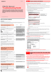
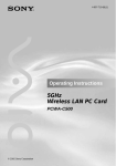
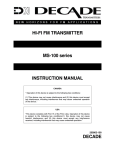
1
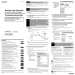
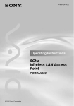
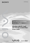
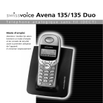
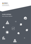
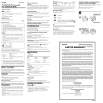
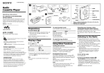
4-674-610-11(1) Router Unit PCWA-R1 Safety Information Introduction WARNING • Opening the unit, for whatever reason, could lead to damage that is not covered by the warranty. • Do not touch the device or accessories during thunderstorms. Electrical shock could result. • This device is made for use in the USA and Canada only. • This device is made for indoor use only. • Do not use this equipment on hospital premises. Doing so may cause medical devices to malfunction. • Do not use this equipment in an aircraft. Doing so could cause the aircraft’s equipment to malfunction. • While using the Wireless Broadband Router, do not cover it or turn it on its side. Do not cover the Wireless Broadband Router with objects such as magazines or newspapers or use it in confined, enclosed places, such as the spaces between walls and furniture. Furthermore, do not turn the Wireless Broadband Router on its side while using it. Either situation could cause heat to build up inside the Wireless Broadband Router, leading to overheating and possible fire. • Exercise care when installing the Ethernet cable, Wireless Unit cable, AC adapter, and power cord. Personal injury or damage to the Wireless Broadband Router could result from people tripping over these. Protect wiring by installing it in places where people do not walk. • Do not swing the Router Unit, Wireless Unit, or AC adapter. Injury could result if they strike a person or fragile material, such as glass. • Keep the Wireless Broadband Router out of the reach of children. Unforeseen injury could result from swallowing loose parts, etc. • Place the Wireless Broadband Router on a stable surface. Do not place the Wireless Broadband Router on wobbly or tilted surfaces. • When hanging the units, make sure that the wall is strong enough to support the Wireless Unit and Router Unit. They may fall if the wall is not strong enough, leading to unforeesen accidents. Further, be careful not to drop the units or the tools used to install them. Doing so could result in unforeseen accidents. • Avoid locations that are directly exposed to sunlight or heat. Internal overheating could result in fire or damage to the unit. • Make sure that the connectors are properly connected. – Do not insert any metallic objects inside the connectors. Short-circuiting the pins could cause fire or damage to the unit. – Be careful to insert connectors squarely. Crooked insertion could cause pins to short-circuit, leading to fire or damage. • Use only the supplied AC adapter with your Sony Wireless Broadband Router. To disconnect your Wireless Broadband Router from the power supply, unplug the AC adapter. • ISDN and telephone lines cannot be connected to the WAN or LAN connectors of the Router Unit. If these connectors are connected to the network or telephone lines mentioned below, high electric current to the connectors may cause damage, overheating, or fire. Connecting to home or business-use telephone lines is strictly prohibited. – Telephone lines – PBX (private branch exchange) – Home or business-use telephone lines – Lines other than those mentioned above For customers in Canada • This class B digital apparatus complies with Canadian ICES-003. • Operation is subject to the following two conditions; (1) this device may not cause interference, and (2) this device must accept any interference, including interference that may cause undesired operation of the device. • To prevent radio interference to the licensed service, this device is intended to be operated indoors and away from windows to provide maximum shielding. Equipment (or its transmit antenna) that is installed outdoors is subject to licensing. • The term “IC” before the equipment certification number only signifies that Industry Canada technical specifications were met. • The installer of this radio equipment must ensure that the antenna is located or pointed in such away that it does not emit an RF field in excess of Health Canada limits for general population. Refer to Safety Code 6, which can be obtained from the Health Canada Web site at http://www.hc-sc.gc.ca/rbc. The PCWA-AR300 is a Wireless Broadband Router that compiles with IEEE 802.11g standards as a wireless LAN access point. It has the following features. Front Wireless Broadband Router Read This First The PCWA-AR300 consists of: • Broadband Router Unit PCWA-R1 • Wireless LAN Access Point PCWA-A320 In this document, we refer to the Broadband Router Unit as the Router Unit and to the Wireless LAN Access Point as the Wireless Unit. PCWA-AR300 Sony Corporation 2003 Printed in Japan WARNING To prevent fire or shock hazard, do not expose the unit to rain or moisture. To avoid electrical shock, do not open the cabinet. Refer servicing to qualified personnel only. Owner’s Record The model and serial numbers are located on the back or bottom of the product. Record the serial number in the space provided below. Refer to them whenever you call your Sony dealer regarding this product. Model No. PCWA-R1 Model No. PCWA-A320 Serial No.____________ Serial No._____________ CAUTION You are cautioned that any changes or modifications not expressly approved in this manual could void your warranty. This device contains the Transmitter Module FCC ID: H8NWLL3020 Exposure to Radio Frequency Radiation The radiated output power of the Wireless Broadband Router is far below the FCC radio frequency exposure limits. Nevertheless, the Wireless Broadband Router shall be used in such a manner that the potential for human contact during normal operation is minimized. FCC Radio-Frequency Exposure Statement This equipment complies with FCC radiation exposure limits, set forth for an uncontrolled environment. This equipment should be installed and operated with a minimum distance of 20 cm (7.9 in.) between the radiator and your body. This transmitter must not be co-located or operated in conjunction with any other antennas or transmitters. NOTE: This equipment has been tested and found to comply with the limits for a Class B digital device, pursuant to Part 15 of the FCC Rules. These limits are designed to provide reasonable protection against harmful interference in a residential installation. This equipment generates, uses, and can radiate radio frequency energy and, if not installed and used in accordance with the instructions, may cause harmful interference to radio or communications. However, there is no guarantee that interference will not occur in a particular installation. If this equipment does cause harmful interference to television reception, which can be determined by turning the equipment off and on, you are encouraged to try to correct the interference by one or more of the following measures: – Reorient or relocate the receiving antenna. – Increase the separation between the equipment and receiver. – Connect the equipment into an outlet on a circuit different from that to which the receiver is connected. – Consult the dealer or an experienced radio/TV technician for help. You are cautioned that any changes or modifications not expressly approved in this manual could void your authority to operate this equipment. If you have questions about this product, call the Sony Customer Information Center at 1-877-760-7669; or write to the Sony Customer Information Center at 12451 Gateway Boulevard, Fort Myers, FL 33913. The number below is for FCC-related matters only. This device must not be co-located or operating in conjunction with any other antenna or transmitter. Declaration of Conformity Trade Name: Sony Model No: PCWA-R1 Responsible Party: Sony Electronics Inc. Address: 680 Kinderkamack Road, Oradell, NJ 07649 USA Telephone: 201-930-6972 This phone number is for FCC-related matters only. This device complies with part 15 of the FCC Rules. Operation is subject to the following two conditions: (1) This device may not cause harmful interference, and (2) this device must accept any interference received, including interference that may cause undesired operation. Declaration of Conformity Trade Name: Sony Model No: PCWA-A320 Responsible Party: Sony Electronics Inc. Address: 680 Kinderkamack Road, Oradell, NJ 07649 USA Telephone: 201-930-6972 This phone number is for FCC-related matters only. This device complies with part 15 of the FCC Rules. Operation is subject to the following two conditions: (1) This device may not cause harmful interference, and (2) this device must accept any interference received, including interference that may cause undesired operation. The shielded interface cable recommended in this manual must be used with the equipment to comply with the limits for a digital device pursuant to Subpart B of Part 15 of the FCC Rules and Canadian ICES-003. Le câble d’interface blindé recommandé dans ce document doit être utilisé avec les appareils pour être conforme aux limitations des appareils numériques telles que spécifiées dans la norme NMB-003 du Canada. NOTE: The power outlet should be installed near the equipment and should be easily accessible. Pour les utilisateurs au Canada • Ces appareils numériques de la classe B sont conformes à la norme NMB-003 du Canada. • L’utilisation de ces appareils est autorisée seulement aux conditions suivantes : (1) ils ne doivent pas produire de brouillage et (2) l’utilisateur des appareils doit être prêt à accepter tout brouillage radioélectrique reçu, même si ce brouillage est susceptible de compromettre le fonctionnement des appareils. • Pour empêcher que ces appareils causent du brouillage au services faisant l’objet de licences, ils doivent être utilisés à l’intérieur et devraient être placés loin des fenêtres afin de fournir un écran de blindage maximal. Si les appareils (ou leurs antennes d’émission) sont installés à l’extérieur, ils doivent faire l’objet de licences. • Le terme « IC » devant le numéro d’homologuation signifie simplement que les normes d’Industrie Canada ont été respectées. • L’installateur de ces appareils radio doit s’assurer que l’antenne soit située ou pointée de manière à ce qu’elle n’émette pas de champs de radiofréquences électromagnétiques supérieurs aux limites spécifiées par Santé Canada pour le grand public. Consultez le code de sécurité 6, disponible sur le site Web de Santé Canada à l’adresse suivante : http://www.hc-sc.gc.ca/rpb. (Opposite side view) qa 0 Wireless Internet access from various locations in your home Using this product as a base station, you can build a network environment from computers with wireless LAN PC cards (installed or built in), and devices with Access Points installed. When this product is connected to a DSL or cable modem, it provides wireless Internet access for computers on the LAN. Connect devices equipped with Ethernet connectors The Router Unit has a LAN connector for Ethernet devices such as desktop computers, to provide Internet access. The IP addresses of connected devices are automatically assigned by the Router Unit, so there is no need to set the IP address of each device manually. PO W ER qh qg qf qd qj qs Bottom qk 0 STATUS indicator Indicates the status of the Router Unit. • Booting: Flashes white • During normal operation: Lights white • During firmware update: Flashes red • If firmware update fails: Continues flashing red after firmware update DSL or cable modem Documentation ❑ Quick Start Guide Describes the required preparations and settings initially necessary to connect to the Internet. z Hint Use a straight-through or cross-over Ethernet cable. qa LINK/ACT indicators Light when a link is established at the LAN connectors qd or WAN connector qf, and flash when sending and receiving data. qg Reset switch Returns Router Unit settings to their factory defaults. See “Resetting to factory default settings” overleaf or Help for details. qs Wireless Unit/LAN connectors Connect to the Access Point or to a device such as a computer with an Ethernet connector. qh DC IN connector Connects to the AC adapter. qd LAN connectors Connect via an Ethernet cable to a device such as a computer with an Ethernet connector. This product is supplied with the following manuals and help files: qf WAN connector Connects via an Ethernet cable to a communication device such as a cable or DSL modem. z Hint Use a straight-through or cross-over Ethernet cable. qj MAC address The Router Unit’s WAN port MAC address is printed here. qk Wall mounting holes Use these holes to hang the Router Unit to a wall. See “Hanging the units” overleaf for details. ❑ Troubleshooting Guide Provides solutions to common problems. ❑ Setup Page Online Help This is Help for the pages used to set up this product. Refer to it for details about setup page operations and setting items of this product. To display the setup page online Help Display the setup page of the Router Unit or Access Point, and click or . Refer to Procedure 4 in the Quick Start Guide for details about how to display the setup page. AC adapter Names of parts and functions Wireless Unit PCWA-A320 Front Rear ql w; (With rear cover removed) ql Power switch Press to turn the device on (?) or off (a). w; 100-240 V AC jack Connect the supplied power cord. Getting help This section describes how to get help and support from Sony, as well as troubleshooting tips for your Wireless Broadband Router. About Sony’s Support Options Sony provides several support options for your Wireless Broadband Router. 7 ❒ Read This First (this manual) contains important information that you should read before using the Wireless Broadband Router. 8 9 ❒ Quick Start Guide explains how to install the Wireless Broadband Router. ❒ Troubleshooting Guide provides solutions to the most common problems users have with their Wireless Broadband Router. ❒ Online Help for the Wireless Broadband Router Setup Page explains how to configure the Wireless Broadband Router. ❒ The Sony Wireless Broadband Router support Web site http://www.sony.com/wirelesslansupport provides the latest information on your Wireless Broadband Router. ❒ The Sony e-mail support service answers your questions by electronic mail. Just send your question in an e-mail message and a customer service representative will reply. To send a question to Sony e-mail support, fill out the e-mail form at http://www.ita.sel.sony.com/support/pc/email.html. ❒ The Sony fax-back service provides you with answers to commonly asked questions. You can use this automated service to request a list of available topics, and then select the topics you want to receive. To contact the Sony fax-back service, call 1-877-760-7669. ❒ The Sony Customer Information Services Center offers information about your Wireless Broadband Router, Wireless LAN PC Card, and other Sony products that work with your computer. To contact the Sony Customer Information Services Center, call 1-877-760-7669. Open 24 hours/day, 7 days/week. 1 STATUS indicator Indicates the status of the Wireless Unit. • Booting: Quickly flashes white • Normal: Slowly flashes white • During firmware update: flashes red • If firmware update fails: Continues flashing red after firmware update 2 Reset switch Returns Wireless Unit settings to their factory defaults. See “Resetting to factory default settings” overleaf or Help for details. 3 LINK/ACT indicator Lights when the Wireless Unit cable is connected to the Wireless Unit/LAN connectors qs on the Router Unit and a link is established, and flashes while sending and receiving. 4 Wireless Unit cable Connects to the Wireless Unit/LAN connectors qs on the Router Unit. 5 Rear cover Remove this cover if you want to hang the Wireless Unit to a wall and to verify the MAC address and Network Name (SSID). See “Hanging the units” overleaf for details about removing the rear cover. • Sony, VAIO, , , and the Eco Info logo are trademarks of Sony Corporation. • Microsoft and Windows are registered trademarks of Microsoft Corporation in the United States and/or other countries. 6 Wall mounting holes Use these holes to hang the Wireless Unit to a wall. See “Hanging the units” overleaf for details. 7 ID The six-character hexadecimal unique product ID is printed here. This ID is used as the default Network Name (SSID) of the Wireless Unit. 8 MAC address The Wireless Unit MAC Address is printed here. 9 Quick Setup switch Use this switch to set up the Wireless LAN Converter PCWA-DE30. Refer to the Quick Start Guide of the Wireless Converter or Help for details. Printed on 100% recycled paper using VOC (Volatile Organic Compound)-free vegetable oil based ink. Continued on next page Factory default settings 2 Installation Precautions Using screws or nails, hang the unit to a wall. • Wireless Unit Specifications • Router Unit Router Unit (PCWA-R1) Refer to the separate Quick Start Guide for information about connecting the Wireless Unit, Router Unit and AC adapter, and how to turn them on. Factory default settings 3.15 Access Point Installation The factory default settings of the Access Point are: Item Default setting Network Name (SSID) The six characters printed on the label under the rear cover of the Access Point (Wireless Unit). 0.94 (2 Disabled Frequency (Channel) Auto Select Broadcast Network Name (SSID) Yes IEEE 802.11 Mode 11g, 11b Access Control Accept all Connection Method Obtain an IP address automatically (DHCP) DNS Server – Speed Auto-Detect Quick Setup Switch Enable Time Server (NTP Server) – 4) Select a secure location for the Wireless Unit or Router Unit where it cannot drop or fall over. Route the cable to the Wireless Unit to suit the installation location. Installation examples • Desktop installation Encryption (WEP) (80) • Hanging Wireless Unit Router Unit units: inches (mm) The Wireless Unit and Router Unit do not come with any sort of fittings used in hanging them. Use screws of sufficient strength to support them. ■ Recommended screws • Roundhead screws Ø0.23 (5.7) Router Unit Ø0.13 (3.1) 0.08 (1.8) homegate – – – – ■ WAN settings Connection Method Speed DHCP Client ID Obtain an IP address automatically Auto-Detect – ■ LAN settings IP Address Subnet Mask DHCP Server IP Address No. 192.168.11.1 255.255.255.0 16 ■ Other information UPN Pass Through UPnP PPTP & IPSec enabled Notes Notes • Do not install at an insecure location. • Do not install at a location where the Wireless Unit or Router Unit could fall as a result of shock or vibration, such as on the edge of a shelf. • Do not install at a location where the Wireless Unit, Router Unit or cables could be accidentally bumped by a person or other objects. • Always use two screws or nails and make sure that the units are secure on the wall. • Select a location that will hold the weight of the units when hanging them to a wall. If the location cannot hold the weight of the units, they may fall and cause accidents. • When hanging the units to walls made of plasterboard or other brittle material, make sure that the material is strong enough to support the units’ weight and use special screw fasteners or other fixtures designed for use with that material. If the units are hung with ordinary screws, they may fall. • When hanging the units to a wall, be careful not to drop the units or the tools used for doing the work. Dropping the units or tools could result in unforeseen accidents. Connecting a computer with a LAN cable To connect a device such as a desktop computer or hub, connect a LAN cable to a LAN connector of the Router Unit. Approx. 5 W Interfaces Interfaces 100BASE-TX/10BASE-T (automatic MDI/MDI-X detection) LAN connector × 4 WAN connector × 1 100BASE-TX/10BASE-T (automatic MDI/MDI-X detection) Maximum external dimensions Approx. 7.9 × 2.8 × 1.3 inches (W × H × D) (approx. 200 × 69 × 32 mm) Protocol support TCP/IP Operating temperature Maximum external dimensions Approx. 3.9 × 3.9 × 1.3 inches (W × H × D) (approx. 98 × 98 × 33 mm) Mass Approx. 11 oz. (approx. 320 g) (incl. connection cable) Recommended number of connected clients 16 or less Protocol support TCP/IP Standards 41°F to 95°F (5°C to 35°C) (no condensation) IEEE 802.11b IEEE 802.11g Storage temperature Radio frequency –4°F to 140°F (–20°C to 60°C) (no condensation) 2.4 GHz wireless network: 2.4 to 2.4835 GHz (IMS band) Maximum connection distance Line of sight approx. 328 feet (100 m) (The maximum connection distance depends on the environment.) WEP (Data encryption) Modulation methods Precautions DS-SS OFDM Operating temperature LAN connectors AC adapter Use only the supplied AC adapter and power cord. Other AC adapters may damage the Wireless Broadband Router. 41°F to 95°F (5°C to 35°C) (no condensation) Storage temperature –4°F to 140°F (–20°C to 60°C) (no condensation) Design and specifications are subject to change without notice. Safety In the table above, “–” indicate blank settings. Do not drop the Wireless Broadband Router. Careful handling helps to prevent damage. Wireless Unit/LAN connectors Resetting to factory default settings Use the following procedure to reset the Access Point or Router Unit to their factory defaults. The procedure is the same for both units and either can be reset independently. • Wireless Unit • Router Unit Reset switch Quick Setup swich Reset switch To computer, etc. Installation z Hints • Use a straight-through or cross-over Ethernet cable. • Connect the Wireless Unit to a Wireless Unit/LAN connector of the Router Unit. • Make the following TCP/IP settings on the computer to be connected: – IP Address setting: Select “Obtain an IP address automatically” – DNS Configuration: With the Windows Me operating system, select “Disable DNS”. With the Windows 2000 and Windows XP operating systems, select “Obtain DNS server address automatically”. Hanging the units 1 • On the Wireless Unit • On the Router Unit Turn on the unit(s). Exposure to rapid changes in temperature or very damp environments can cause condensation on internal parts. This may prevent the Wireless Broadband Router from operating properly. If this should happen, unplug the AC adapter from the power outlet and allow the Wireless Broadband Router to dry for two to three hours. Cleaning Clean the casing with a soft cloth lightly moistened with water or a mild detergent solution. Do not use any type of abrasive pad, scouring powder, or solvent such as alcohol or benzene. This may damage the finish of the casing. With a paper clip, press and hold the Reset switch for at least one second on the bottom of the Wireless Unit or the side of the Router Unit that you want to reset. To hang the Wireless Unit to a wall, remove the rear cover by sliding it in the direction of the arrow. Be careful not to press the Quick Setup swich by mistake when you reset the Wireless Unit. When the Status indicator flashes, release the Reset switch. The Wireless Unit or Router Unit restarts automatically with all settings returned to their factory defaults. Do not place the Wireless Broadband Router where it is exposed to the following conditions: • Unstable surfaces • High humidity or poor ventilation • Excessive dust • Direct sunlight or extreme heat • Closed cars • Magnetic fields (near magnets, speakers, or televisions) • Frequent vibration • Locations where the transmission of radio waves may be obstructed by metal plates or concrete walls Operation Locate the wall mounting holes. Note 3 Power consumption Approx. 5 W 64 bits/128 bits Note 1 2 Power consumption 16 or less Default setting ■ Common settings Host Name Administrator Password Guest Password Time Server (NTP server) DNS Server DC 12 V (Supplied by the PCWA-R1) Recommended number of connected clients units: inches (mm) Item Power AC100 - 240 V, 50/60 Hz (The power cord plug is for use with AC 120 V.) Approx. 12 oz. (approx. 340 g) Ø0.25 (6.2) Ø0.13 (3.1) 0.1 (2.3) Power Mass • Flathead screws Access Point (PCWA-A320) Bottom Note Be cautious when removing or replacing the cover of the Wireless Unit. z Hint To replace the rear cover of the Wireless Unit, align the rails on the rear of the Wireless Unit with the grooves in the rear cover, and slide it upwards. Emergencies In case of an emergency, stop the wireless functions by unplugging the power cord.