1
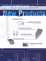
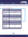
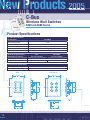
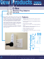
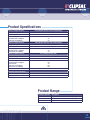
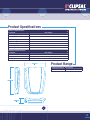
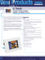
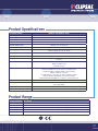
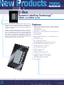
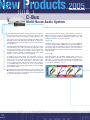
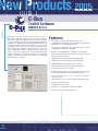
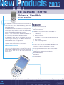
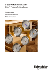
clipsal.com/cis
Contentss -
New
w Products
Prod
Pro
ro
2005
2005
05
2
Contents – New Products 2005
Introduction to New Products 2005
C-Bus Wireless System
C-Bus Wireless Wall Switches, 5850 and 5880 Series
C-Bus Wireless Plug Adaptors, 5812 Series
C-Bus Wireless Remote Control, 5888 Series
C-Bus Wireless Gateway, 5800 Series
C-Bus Colour Touch Screen, 5080CTC and 5050CTC Series
C-Bus DLTTM, 5080DL and 5050DL Series
24
4
26
28
30
0
32
34
4
36
38
2
4
6
10
0
14
16
16
18
20
22
22
C-Bus Multi-Room Audio System
C-Bus Audio Matrix Switcher
C-Bus Audio Distributor
C-Bus Audio Amplifiers
Schedule Plus and Homegate Software V3
C-Bus Toolkit Software
Infrared Distribution System, 8050 Series
Universal, Hand Held IR Remote Control
3
IIntroduction
nt dutoction
ntroduction
ti
New
Ne
N
e Produ
Products
Pr
P
s
C-Bus Wireless System
A retrofitable solution for Home Automation.
C-Bus Wireless Wall Switches
Allows existing 240V wall switches to be replaced with
C-Bus Wireless technology.
C-Bus Wireless Plug Adaptors
Allows devices plugged into 240V General Purpose Outlets
to be controlled using C-Bus Wireless technology.
C-Bus Wireless Remote
Allows control of C-Bus Wireless Wall
Switches and Plug Adaptor units remotely.
C-Bus Wireless Gateway
Allows a C-Bus Wireless network to be linked to a C-Bus Cat-5 wired network.
C-Touch Colour Touch Screen
Provides an elegant wall mounted interface
to a C-Bus system.
4
20
2005
TM
Dynamic Labelling Technology
An elegant solution for easy and flexible switch labelling.
C-Bus Multi-Room Audio System
Listen to and conveniently control music anywhere in the home.
C-Bus Schedule Plus and HomeGate Software V.3
Includes a number of major new features, including a
fully featured programmable logic engine.
C-Bus Toolkit Software
Includes an overhauled version of the C-Bus installation
software with enhanced features and usability.
IR Distribution System
A flexible, cost effective multi-zone Infrared Distribution System.
Universal IR Remote Control
Allows users to control C-Bus and a wide range of other electronic
devices that are equipped with infrared control.
5
New Products
Pr
2005
C-Bus
Wireless System
The C-Bus Wireless product range incorporates a family of
C-Bus Radio Frequency (RF) devices, including Wall
Switches, Plug Adaptors, a hand held Remote Control and a
Gateway to Cat-5 Wired C-Bus units.
C-Bus Wireless Wall Switches are designed to easily
replace standard, 240V wall switches. They incorporate
patented Clipsal technology and are two wire devices
requiring no neutral connection (240V a.c. active and load
connections only).
All C-Bus Wireless units incorporate Clipsal C-Bus’ unique
Learn Mode functions for programming devices.Wall Switches,
Plug Adaptors and the Gateway unit can also be programmed
via the C-Bus Toolkit software. Multiple C-Bus Wireless units
can be linked into a common network using Learn Mode or the
C-Bus Toolkit software.
Associations can be created between buttons on multiple
units, so that a button press on one unit will operate a button
on another unit or units.
C-Bus Wireless units include scene capabilities, which allow
the user to perform a series of actions across multiple outputs
by pressing a single button. For example, on arrival home a
home owner could use a scene to switch on lights in the
hallway, kitchen and lounge, and also switch on a heater.
Programming a C-Bus Wireless Unit via C-Bus Toolkit Software
The diagrams below show two of the many possible basic
C-Bus Wireless unit installations. Room A uses stand-alone
units, which can be switched via the Wireless hand held
Remote Control. Room B uses networked units where buttons
on one unit can operate other units or trigger scenes.
Room A Grouping C-Bus
Wireless Units
via Learn Mode
Stand Alone C-Bus Wireless Units
Room B Networked C-Bus Wireless Units
6
Basic Operation
Buttons on a Wireless Wall Switch or Plug Adaptor are
organised in pairs that control the output channels. Remaining
pairs (free buttons) are used to control outputs on other units
when multiple C-Bus Wireless units are configured as part of
a network. For example, the figure below shows a 6 button, 2
channel Saturn Wireless Dimmer unit. Its buttons perform the
following functions:
Buttons 1 and 2 control the first channel. (A quick press
on either button toggles the channel on or off. A long
press on button 1 or 2 dims down or up alternatively).
Buttons 3 and 4 control the second channel.
Buttons 5 and 6 are unused when the unit is used as a
stand-alone unit. They may be used to control outputs on
other units when part of a multi-unit network.
When a C-Bus Wireless Wall Switch or Plug Adaptor unit is first
installed, it functions as a stand-alone unit. In this basic default
mode, the unit functions as a dimmer or switch, depending on
the model.
C-Bus Wireless Plug Adaptors have one output channel (a
single, 240V a.c. socket) and two buttons. Wall plate units
are available in one or two output channel versions, with
two, four, six or eight buttons (eight button, Neo only). Each
channel controls one or more lights or other electrical devices
connected to its output.
7
New Products
Pr
2005
C-Bus
Wireless System
C-Bus Wireless Networks
Mode 1
To experience the full capabilities of wireless operation,
C-Bus Wireless units are linked together to form a network.
Stand-Alone Mode
In this mode, C-Bus Wireless Wall Switches and Plug Adaptors
act as stand-alone dimmers or switches and make no use of
the inbuilt wireless capabilities. No setup is required for this
mode; Plug Adaptors simply plug into the mains, and Wireless
Wall Switches are installed by a licensed electrician in place of
existing wall switches. The buttons on the units control the local
dimming or switching channels of the unit only.
To communicate with each other, all units within the same
network should be located within 15 to 20 metres of each
other. This distance depends on building materials used.
Up to 30 units may be connected within the same C-Bus
Wireless network.
Mode 2
Simple Remote Controlled Mode
In this mode, a C-Bus Wireless Wall Switch acts as a standalone dimmer or switch and a C-Bus Wireless Remote Control
operates the Wall Switch from a distance. This mode is simple
to set up and is suitable for small installations where networking
is not needed. C-Bus Wireless Wall Switch or Plug Adaptor units
are controlled using a C-Bus Wireless Remote: In this mode, the
buttons on the Wireless Wall Switch control the local dimming or
switching channels of the unit, and the Remote Control is linked
to buttons on a Wall Switch using a Learn Mode operation. No
PC is required to configure this mode.
C-Bus Wireless Network Security
C-Bus Wireless units can optionally use 128-bit encrypted
messages to communicate with each other. This results in
a highly secure network.
Nearby C-Bus Wireless Networks
It is possible to have several separate networks present
alongside each other without interferance, as each separate
C-Bus Wireless network has an automatically assigned,
unique ‘House Code’.
C-Bus Wireless Modes of Operation
C-Bus Wireless units have five major modes of operation.
8
Mode 3
Networked Mode
In this mode, a C-Bus Wireless Wall Switch acts as a dimmer or
switch and multiple C-Bus Wireless units can be linked to each
other with the C-Bus Wireless technology. This mode is simple to
setup, and is suitable for more complex installations. In this mode,
local control buttons control the dimming or switch channel of the
unit, and may also control other C-Bus Wireless units. Free buttons
can control the dimmer or switch channels of other units via a
C-Bus Wireless network established using Learn Mode operations.
The operation of buttons is set using Learn Mode operations or
using the C-Bus Toolkit Software.
Mode 4
Networked with Remote
In this mode, a C-Bus Wireless Wall Switch acts as a dimmer or
switch and multiple C-Bus Wireless units can be linked to each
other with the C-Bus Wireless technology. Local control buttons
control the dimming or switch channel of the unit, and may also
control other C-Bus Wireless units. Free buttons can control the
dimmer or switch channels of other units via a C-Bus Wireless
network established using Learn Mode operations or C-Bus
Toolkit software. Buttons on the Wireless Remote are linked to
Wall Switch and Plug Adaptor buttons as desired.
Mode 5
Networked mode in combination with Cat-5 wired C-Bus units
The C-Bus Wireless Gateway is used to link a C-Bus Wireless
network to a C-Bus Cat-5 wired network. It is functionally
equivalent to a C-Bus Network Bridge. Using the Gateway, C-Bus
Wireless and Cat-5 networks can communicate and interact with
each other. Both Wireless and Cat-5 Networks use the same
command structure, and are 100% compatible.
9
New Products
Pr
2005
C-Bus
Wireless Wall Switches
5850 and 5880 Series
C-Bus Wireless Wall Switches allow existing, standard 240V a.c.
wall switches to be replaced with a wall switch containing
C-Bus Wireless technology. C-Bus Wireless Wall Switches are
able to communicate with other C-Bus Wireless devices
using Radio Frequency wireless messaging and form a
C-Bus Wireless Network.
Features
Replaces standard, existing wall switches.
Two-Wire connection (no neutral required).
Communicates directly with other C-Bus Wireless devices.
The Wall Switches are two-wire devices (240V a.c. active and
load), with no neutral connection required. This enables
the wall switches to be installed with minimal changes to the
existing mains wiring.
Can be controlled via C-Bus Cat-5 Wired Input Units (via a
Gateway Unit), such as Touch Screens.
The control buttons on the Wall Switches are able to control
a load connected to the Wall Switch directly and can also
control loads connected to other C-Bus Wireless devices.
Each control button can be programmed to function as an
on/off switch, a dimmer, or can issue a scene, as well as a
number of other options.
128-encrypted communications.
Unique C-Bus Wireless House Code.
Programmable via C-Bus Learn features or via C-Bus
Toolkit software.
1 Channel and 2 Channel versions.
Leading Edge and Trailing Edge Dimming Units, 1 Channel
500VA and 2 Channel 250VA per channel.
Relay unit, 1 Channel 8A (fluorescent) rating and 2 Channel
4A (fluorescent) per channel.
Available in Neo and Ulti Saturn style.
Neo
10
Ulti Saturn
Product Specifications
Electrical Specifications
Supply Voltage
2-Wire Leading Edge Dimmer Units – 1 & 2 Channel
240V a.c. @ 50Hz
Min. Load Per Channel
25W Lamp or 0.25A Fan Motor
Max. Load Per Channel
500W, 2A (Single Channel Unit)
250W, 1A (Two Channel Unit)
Load Rating
Incandescent / Halogen
Iron Core LV Lighting
Fan Motors
Off State Power Consumption
Off State Leakage Current
Electrical Specifications
Supply Voltage
2A
2A
2A
0.5W
12mA Channel 1, 5mA Channel 2
2-Wire Trailing Edge Dimmer Units – 1 & 2 Channel
240V a.c. @ 50Hz
Min. Load Per Channel
25W Lamp
Max. Load Per Channel
500W, 2A (Single Channel Unit)
250W, 1A (Two Channel Unit)
Load Rating
Incandescent / Halogen
Electronic LV Lighting
Off State Power Consumption
Off State Leakage Current
Electrical Specifications
Supply Voltage
2A
2A
0.5W
15mA Channel 1, 10mA Channel 2
2-Wire Switch Units – 1 & 2 Channel
240V a.c. @ 50Hz
Min. Load Per Channel
25W, 0.1A
Max. Total Load
2000W, 8A
Load Rating
Incandescent / Halogen
Fluorescent ¹
Iron Core LV Lighting
Electronic LV Lighting
Fan Motors
Off State Power Consumption
Off State Leakage Current
8A
4A
8A
8A
2A
0.25W
10mA Channel 1, 0mA Channel 2
¹ Fluorescent luminaire requires Power Factor Correction (PFC) capacitor fitted in order for switch
unit to function correctly.
11
New Products
Pr
2005
C-Bus
Wireless Wall Switches
5850 and 5880 Series
Product Specifications
RF C-Bus Specifications
RF Frequency
433.92MHz
Transmitting Power
1mW
Maximum Range
Control Functions
50m (Typical 15m - 20m)
Load Switching, Dimming (LE / TE only), Timer, Relay
Status Indicator
Orange
Warm-Up Time
Mechanical Specifications
Dimensions (L x W x H)
5 Seconds
Neo
Ulti Saturn
116 x 76 x 38.5mm
116 x 76 x 41mm
Mounting Centres
Weight
84mm
133g
186g
Environmental Specifications
Operating Temp. Range
Operating Humidity Range
Neo
12
0 – 40ºC
10 – 95% R.H.
Ulti Saturn
Product Range
C-Bus Wireless Wall Switch Dimmer Units
Channels
Type
Current
Part Number
Neo
1
Leading Edge
2A
2
Leading Edge
1A
1
Trailing Edge
2A
2
Trailing Edge
1A
1
Leading Edge
2A
2
Leading Edge
1A
1
Trailing Edge
2A
2
Trailing Edge
1A
2 Button
4 Button
8 Button
5852D2L1AA
5854D2L1AA
5858D2L1AA
–
5852D2T1AA
–
E5852D2L1TA
–
E5852D2T1TA
–
Leading Edge
2A
2
Leading Edge
1A
1
Trailing Edge
2A
2
Trailing Edge
1A
1
Leading Edge
2A
2
Leading Edge
1A
1
Trailing Edge
2A
2
Trailing Edge
1A
5858D1L2AA
5858D2T1AA
5854D1T2AA
5858D1T2AA
E5854D2L1TA
E5858D2L1TA
E5854D1L2TA
E5858D1L2TA
E5854D2T1TA
E5858D2T1TA
E5854D1T2TA
E5858D1T2TA
2 Button
4 Button
6 Button
5882D2L1AA
5884D2L1AA
5886D2L1AA
5884D1L2AA
5886D1L2AA
5884D2T1AA
5886D2T1AA
5884D1T2AA
5886D1T2AA
E5884D2L1TA
E5886D2L1TA
Ulti Saturn
1
5854D1L2AA
5854D2T1AA
–
5882D2T1AA
–
E5882D2L1TA
–
E5882D2T1TA
–
E5884D1L2TA
E5886D1L2TA
E5884D2T1TA
E5886D2T1TA
E5884D1T2TA
E5886D1T2TA
C-Bus Wireless Wall Switch Relay Units
Channels
Current
Neo
1
8A
2
4A
1
8A
2
4A
Ulti Saturn
1
8A
2
4A
1
8A
2
4A
Part Number
2 Button
4 Button
8 Button
5852R8F1AA
5854R8F1AA
5858R8F1AA
5854R4F2AA
5858R4F2AA
E5854R8F1TA
E5858R8F1TA
E5854R4F2TA
E5858R4F2TA
–
E5852R8F1TA
–
2 Button
4 Button
6 Button
5882R8F1AA
5884R8F1AA
5886R8F1AA
5884R4F2AA
5886R4F2AA
E5884R8F1TA
E5886R8F1TA
E5884R4F2TA
E5886R4F2TA
–
E5882R8F1TA
–
13
New Products
Pr
2005
C-Bus
Wireless Plug Adaptors
5812 Series
C-Bus Wireless Plug Adaptors allow devices normally
plugged into 240V a.c. General Purpose Outlets (for
example, lounge or bedside lamps) to be controlled using
C-Bus Wireless technology. C-Bus Wireless Plug Adaptors
are able to communicate with other C-Bus Wireless devices
(such as Wireless Wall Switches) using Radio Frequency
wireless messaging and form a C-Bus Wireless Network.
C-Bus Wireless Plug Adaptors plug into existing Power
Outlets, and the device to be controlled via C-Bus Wireless
then piggybacks into the Plug Adaptor. No additions or
alterations to existing wiring are required.
C-Bus Wireless Plug Adaptors are available in Leading Edge
Dimming and Trailing Edge Dimming Units, as well as a
Relay output version.
Features
Plugs into a Standard Australian General Purpose
electrical outlet.
Communicates directly with other C-Bus Wireless devices.
Separate Leading Edge and Trailing Edge Dimming
units available.
Relay output version available.
Integral, easily accessible control/override/programming
buttons.
Can be controlled via C-Bus Cat-5 wired Input Units (via a
Gateway Unit), such as Touch Screens.
Unique C-Bus Wireless House Code.
128-bit encrypted communications.
Programmable via C-Bus Learn features or via C-Bus
Toolkit software.
14
Product Specifications
Electrical Specifications
Plug Adaptor Dimmer Unit (Leading Edge)
Supply Voltage
240V a.c. @ 50Hz
Max. Total Load
750W, 3A
Load Rating
Incandescent / Halogen
Iron Core LV Lighting
3A
3A
Electrical Specifications
Plug Adaptor Dimmer Unit (Trailing Edge)
Supply Voltage
240V a.c. @ 50Hz
Max. Total Load
500W, 2A
Load Rating
Incandescent / Halogen
Electronic LV Lighting
2A
2A
Electrical Specifications
Plug Adaptor Switch Unit
Supply Voltage
240V a.c. @ 50Hz
Max. Total Load
2400W, 10A
Load Rating
Incandescent / Halogen
Fluorescent
Iron Core LV Lighting
Electronic LV Lighting
10A
4A
10A
10A
Fan Motors
2A
Mechanical Specifications
Dimensions (L x W x H)
123 x 50 x 64mm
Weight
118g
Product Range
Catalogue Number
Description
5812D3L1AA
Plug Adaptor Dimmer Unit (Leading Edge)
5812D2T1AA
Plug Adaptor Dimmer Unit (Trailing Edge)
5812R10F1AA
Plug Adaptor Switch Unit
15
New Products
Pr
2005
C-Bus
Wireless Remote Control
5888 Series
The C-Bus Wireless Remote Control allows a user to control
buttons on C-Bus Wireless Wall Switch and Plug Adaptor
units remotely. Unlike an infrared (IR) remote, it utilises radio
frequency (RF) communication therefore, the user does not
need to point it directly at the unit to be controlled.
Up to 10 separate Wall Switch or Plug Adaptor buttons
can be controlled by the Remote Control unit. These can be
on various units on different networks. A single button on a
Wall Switch or Plug Adaptor unit can be controlled by up to
two remote controls.
The Remote Control buttons are organised in two banks of
five buttons. Banks are alternately selected by pressing the
Shift button.
Up and Down buttons allow the user to dim the level associated
with the last button selected (on dimmer units). An ‘All Off’
button provides a convenient way to switch off all buttons that
have been associated with the remote control unit.
Features
Five programmable function buttons, with Shift button
providing five more programmable functions.
C-Bus Wireless Groups and Scenes can be controlled
from the remote.
Up, down, off and “shift” buttons.
Blue LED Backlight.
LCD display.
Button labelling.
Transmit Indicator.
20-25m range (typical).
Programming / learn switch.
A single C-Bus Wireless unit can be controlled by 1 or 2
Remotes.
A key on a Remote can be linked to several different C-Bus
Wireless units.
Different buttons on the same Remote can be linked to
different C-Bus Wireless units.
16
Product Specifications
Electrical Specifications
RF Frequency
433.92 MHz
Transmitting Power
10mW
Typical Range
20-25m
Maximum Range
Backlighting
Display
Batteries
70m (free air)
Blue LEDs
LCD
2 x AAA
Mechanical Specifications
Dimensions (L x W x H)
Weight
149 x 52 x 26mm
87g (including batteries)
Product Range
Catalogue Number
Description
5888TXBA
C-Bus Wireless Hand Held Remote
17
New Products
Pr
2005
C-Bus
Wireless Gateway
5800 Series
The C-Bus Wireless Gateway is used to link a C-Bus Wireless
network to a C-Bus Cat-5 Wired network. It is functionally
equivalent to a C-Bus Network Bridge. Using the Gateway,
C-Bus Wireless and Cat-5 networks can communicate and
interact with each other. Both Wireless and Cat-5 Networks
use the same command structure.
The Gateway allows:
Control of a C-Bus Wireless network, via control units
on a C-Bus wired network, or from software such as
Schedule Plus or HomeGate.
Control of output units and electrical loads in one network
type, from Input Units (such as switches) in the other
network type.
Features
Allows seamless communication between a wired C-Bus
network and a C-Bus Wireless Network.
Desktop or wall mounted.
A C-Bus Cat-5 cable connected to the wired C-Bus network
is plugged into an RJ45 socket at the rear of the Gateway.
Power for the Gateway is provided by the wired C-Bus
network, no additional power source is required.
The connection to a C-Bus Wireless network is
accomplished by a C-Bus Learn Mode operation.
The connection to a C-Bus Cat-5 wired network requires
the use of the C-Bus Toolkit software.
The Gateway supports routing of messages into and
through both wired and wireless networks.
Messages on each network (such as button presses) can
be passed through to the adjacent network.
A Gateway links Cat-5 wired and Wireless
networks together
18
Product Specifications
Electrical Specifications
Parameter
C-Bus supply voltage
RF frequency
Transmitting power
Typical range
Maximum range
Operating temperature range
Operating humidity range
Description
15 to 36 V d.c., 32 mA
433.92 MHz
1 mW
15 to 20 m
50 m (open air)
0 to 40 °C
10 to 95% RH
Mechanical Specifications
Parameter
Dimensions (W×H×D)
Description
105 × 149 × 26 mm
Weight
105 g
Fixing centres
40 mm
Product Range
Catalogue Number
Description
5800WCGA
Wireless Gateway
19
New Products
Pr
2005
C-Touch
Colour Touch screen
5080CTC and 5050CTC Series
C-Touch Colour Touch Screen provides a wall mounted, touch
sensitive LCD screen that can display pages of graphical
items, such as buttons, sliders and images. These graphical
items perform C-Bus related functions when pressed.
The unit also includes a real time clock for automatic
scheduling of events based on the time of day, week, month
or year. The touch screen allows control via an Infrared handheld remote control unit.
C-Touch Colour can be completely customised to suit
user requirements via the included Windows™ compatible
configuration software. The software also includes a Logic
Engine module that allows the installer to program logic based
(if-then-else) control into the touch screen configuration.
Available in Neo and Ulti Saturn Glass style surrounds,
the Colour Touch Screen is aesthetically appealing and an
extremely functional addition to the comprehensive range of
C-Bus products.
Features
General
Connects directly to a C-Bus network (no external PC
Interface required).
Control and Monitor devices connected to C-Bus and
RS-232 (Custom RS-232 support via the included logic
programming language).
On-board audio supports external speakers.
Programmable via Ethernet.
Real Time Clock (astronomical).
256Mb Compact Flash (upgradeable to 1Gb) factory
programmed with Touch Screen firmware.
Software
GUI based drag and drop configuration software, plus
freeform logic programming language.
Software interface design supports 101 levels of alpha
blending.
Animated buttons with more than 256 animation frames
supported.
Fully customisable graphics including bar graphs, sliders,
percentage indicators, images, gauges and clocks with
any border and background style.
Supports project theme templates.
Audio WAV file support.
Scene Control.
Event Scheduling support.
Astronomical Clock Support.
Irrigation Control.
Password access control.
20
Product Specifications
Catalogue Number
5080CTC and 5050CTC Series
Screen Type
LCD active Matrix
Screen Size
6.4 inch (diagonal)
Screen resolution
VGA, 640 x 480 pixels
Pixel Pitch
0.204mm(H) x 0.202mm(V)
Screen viewing area
130.6(H) mm x 97.0(V) mm
Touch Overlay type
Resistive membrane
Viewing Angle:
Horizontal: typical. 70° left and right
Vertical: typical. 40° up, 70° down
Luminance
300cd/ m2
Backlight
Cold Cathode with Light sensor for automatic backlight level control
Memory
256MB Compact Flash (upgradeable to 1 GB) factory programmed with panel
firmware
Front Panel
Ethernet 10/100 Port: RJ-45 port (under facia)
Speaker (under facia)
Infrared receiver
Rear Connectors
C-Bus RJ-45 connectors, x 2
Ethernet 10/100 Port: RJ-45 port for communication
Composite video output via RCA socket (75ohm)
RS232 via DB 9 connector
2 x USB (type A connectors) for future software support
Remote IR input (hardwired via 3.5mm mini-jack)
External Speaker/Headphone Connector: 3.5mm mini-jack.
Enclosure
Moulded Faradex
Fascia
Ulti Saturn Style: Glass
Neo Style: ABS
Power
<5A @ 5Vd.c. (Power pack ordered seperately)
Dimensions (WHD)
248mm x 175mm x 60mm
Product Range
Catalogue Number Description
5080CTC, GF
C-Bus Colour Touch Screen, 6.4 inch screen, Ulti Saturn Glass Style, White
5080CTC-680
C-Bus Colour Touch Screen, 6.4 inch screen, Ulti Saturn Glass Style, Black
5080CTC-380
C-Bus Colour Touch Screen, 6.4 inch screen, Ulti Saturn Glass Style, Cream
5080CTC-780
C-Bus Colour Touch Screen, 6.4 inch screen, Ulti Saturn Glass Style, Mid-Brown
5050CTC
C-Bus Colour Touch Screen, 6.4 inch screen, Neo Style, Battleship Grey and Brushed Aluminium*
* Other Colours Available, please contact Clipsal.
21
New Products
Pr
2005
C-Bus
Dynamic Labelling Technology
TM
5080DL and 5050DL Series
Clipsal’s new Dynamic Labelling Technology™ has been
incorporated in C-Bus Saturn and Neo units allowing C-Bus
installers to electronically label switches according to the
requirements of the user and easily change this labelling via
software, as required.
Dynamic Labelling Technology™ switches incorporate
editable LCD text or bitmap labels, plus function indicators
such as bar-graphs. The units have eight programmable
buttons for C-Bus Group/Scene control over two pages, with
a Scroll button to toggle between these pages. The 64 x 128
pixel LCD screen incorporates a backlight. Text, sliders and
bitmaps can be defined in the C-Bus Toolkit software and
downloaded to the unit via a C-Bus network.
Features
Editable LCD Labels with Dynamic Graphic Displays
called Function Indicators, which can be optionally
enabled/disabled.
LCD labelling for each button.
Eight buttons for C-Bus group/Scene over two pages (four
buttons per page).
Page/scroll button.
Each can be programmed as on/off, dimming, time or
scene control.
64 x 128 pixel screen.
Up to 8 Languages supported.
Downloadable bitmaps per group address or Scene.
Dimmable White LED backlighting for the LCD.
Dimmable Blue LED on each button.
Ignore first button press option.
Fallback to page 1 option.
Time Clock Display.
Available in Saturn and Neo styles.
Programmed via C-Bus Toolkit software.
Nightlight on all buttons or just 5th button.
LCD feedback under Learn Mode.
Scene dimming.
22
Product Specifications
Catalogue Number
5080DL and 5050DL Series
C-Bus Supply Voltage
15 - 36V d.c.
Current Drawn
22mA
AC Input Impedance
50k @ 1kHz
Max. No. of Units on Network
Control Functions
50 units
Load switching, Dimming, Timing, Scene Control
Warm-Up Time
5 seconds
Storage Temperature Range
-10 - 60°C
Operating Temperature Range
0 - 45°C
Operating Humidity Range
C-Bus Input Terminals
-10 - 95% R.H.
0.2 - 1.5mm2 (24-16AWG)
Ulti Saturn
Neo
Product Range
Catalogue Number Description
5085DL, GF
Ulti Saturn Glass, rectangular style C-Bus switch, incorporating Dynamic
Labelling Technology, 5 buttons, White*, Learn Enabled.
EA5084DL, GF
Ulti Saturn Glass, square style C-Bus switch, incorporating Dynamic Labelling
Technology, 4 buttons, White*, Learn Enabled.
5055DL
Neo, rectangular style C-Bus switch, incorporating Dynamic Labelling
Technology, 5 buttons, Battleship Grey and Brushed Aluminum, Learn Enabled.
E5054DL
Neo, square style C-Bus switch, incorporating Dynamic Labelling Technology,
4 buttons, Battleship Grey and Brushed Aluminum, Learn Enabled.
*Also available in black, mid-brown and cream.
23
New Products
Pr
2005
C-Bus
Multi-Room Audio System
The C-Bus Multi-Room Audio System allows users to listen to
and control audio sources from convenient locations around
a home. The system is both simple to install and easy to use.
The system has been designed utilising new digital audio
distribution technology (developed by Clipsal), in conjunction
with Clipsal C-Bus core technology for system communication
and integration.
Clipsal’s digital audio distribution technology allows for noise
and interference free audio reproduction, whilst the C-Bus
technology allows the audio products to be seamlessly
integrated and used with all existing C-Bus products. For
example, volume can all be controlled from the same C-Bus
Switch or Touch Screen which controls lighting.
In addition, the system allows any input audio source to
be made available in any audio zone. Changes to the input
audio source can easily be made by the user from a local
C-Bus device at any time, regardless of where the audio
source equipment (e.g., CD Player) is physically located. It
is compatible with most audio sources; it accommodates
standard stereo line level analogue inputs as well as digital
audio TOSlink inputs.
Infrared signals from hand held remote controls can be routed
through the system by connecting IR targets and emitters. IR
commands can also be stored by the system and activated
by programmed C-Bus commands.
24
The C-Bus Multi-Room Audio System allows a number of
different system layout options. This flexibility allows for a wide
range of customer needs and installation requirements. Two
example schematics are shown opposite.
Option A
This basic option allows a single audio source to be available to
a number of C-Bus Audio Amplifiers and to be controlled from
convenient locations around the home (via any combination of
C-Bus input devices). This option requires one Cat-5 cable for
the Audio distribution, with this cable cascaded between each
Audio Amplifier.
Option B
This option allows more flexibility. Multiple audio sources are
made available to all audio zones, with all the audio sources
selectable on a zone-by-zone basis via C-Bus Input Devices.
This option requires a separate (star wired) Cat-5 Audio cable
to each Audio Amplifier in a zone.
Option A
Option B
Note 1
Depending on the number of amplifiers in an installation, and their
power rating (25W or 10W RMS), C-Bus Audio Amplifiers may
require a local power-pack connection.
Note 2
The C-Bus Audio Distributor and Matrix Switcher are able to
supply a limited amount of power to the Audio Amplifiers, as the
system shares power available via the Cat-5 Audio network.
25
New Products
Pr
2005
C-Bus
Audio Matrix Switcher
Cat No. 5560884
The Audio Matrix Switcher is a C-Bus unit, which switches
four stereo audio inputs to any of the eight available digital
audio outputs. These digital outputs are then distributed to
C-Bus Audio Amplifiers via Cat-5 data cable. Switching audio
sources is achieved via any C-Bus input device or via the
control panel on the front of the Matrix Switcher.
Features
Digital audio distribution technology, for noise free audio
reproduction.
Four stereo analogue audio source inputs.
Eight digital audio zone outputs (~45m for each star wired
output).
Cat-5 cable connection between Matrix switcher and
amplifiers
Two mono annunciation inputs.
Voice annunciation of channel changes. (selectable)
One fibre-optic SPDIF input.(digital audio compatible)
One custom digital input to allow cascading of units.
C-Bus infrared output (2 zones) for third party equipment
control.
Reticulated IR support.
User interface consisting of LCD display and tactile
feedback switches.
C-Bus messages control selection of input/output routing.
Internal 400mA C-Bus PSU.
Internal 4A PSU for the amplifiers.
Configuration setup through either C-Bus or USB.
Control via C-Bus input devices, such as C-Bus Wall
Switches, Touch Screens, etc.
26
Product Specifications
Provisional Specifications
Design Technology
16-bit Audio Path
Sampling Rates
48kHz
Source Inputs
4 Stereo Line Level Analogue
2 Mono all channel inputs
1 Digital Audio
1 TOSlink
Zone Outputs
8 Digital Audio outputs
Expansion
Power Distribution
Up to 3 Matrix Switches per system
Centralised power sufficient for 6W per channel for each
of 8 zones. Additional power requires local amplifier
power supplies.
Analog Inputs
4 Line Level Stereo
Analog Loop Through
Use looping connectors
Digital Audio Input
RJ45 and TOSlink (48KHz)
Analog Input Impedance
47k ohms
Digital Input Impedance
110 ohms
IR Outputs
2 x C-Bus controlled IR ports + Reticulated IR
Controller Connectors
C-Bus (RJ45)
Home Control System Interface
C-Bus
Source Input Connectors
RCA/RJ45/TOSlink
Power Connector
IEC
Digital Audio Connections
Wiring Specification
Cat-5
Connectors
RJ45 8P8C
C-Bus
Current Drawn
18 mA
C-Bus PSU
400mA
Dimensions
424mm(W) x 267mm(D) x 66mm(H)
Product Range
Catalogue Number
Description
5560884
C-Bus Audio Matrix Switcher for Multi-Room Audio System.
27
New Products
Pr
2005
C-Bus
Audio Distributor
Cat No. 560011
The Audio Distribution unit is used to distribute a single
stereo audio source to C-Bus Audio Amplifiers via a digitised
signal over Cat-5 cable. This unit does not require any C-Bus
programming.
Features
One stereo analogue audio source input.
One digital audio output (cascadable to multiple zones).
Cat-5 cable connection between Distributor and amplifiers.
Provides limited power for amplifiers (with dc power pack
connected).
Output can be looped between C-Bus Audio Amplifiers.
Infrared emmiter output.
28
Product Specifications
Provisional Specifications
Design Technology
Sampling Rates
Source Inputs
Outputs
Power Distribution
16-bit Audio Path
48kHz
1 Stereo Line Level Analogue
1 Digital Audio output
Unit can use a local power supply (24V a.c./DC) or if
connected to an amplifier, obtain power from the amp.
Analogue Input Impedance
47k ohms
Digital Input Impedance
110 ohms
Source Input Connectors
Power Link Jack
RCA
DC power jack or power via amplifier
Digital Audio Connections
Wiring Specification
Cat-5
Connectors
RJ45 8P8C
Dimensions
165mm(W) x 50mm(D) x 40mm(H)
Product Range
Catalogue Number
Description
560011
Audio Distribution Unit,
one stereo audio input
source and one digital
output source.
29
New Products
Pr
2005
C-Bus
Audio Amplifiers
5601 Series
Desktop Audio Amplifier
The desktop mounted, C-Bus Stereo Audio Amplifier,
is rated at 25 Watt/Channel (RMS). Volume, Bass, Treble
and Balance are all adjustable via C-Bus input devices. The
Desktop Amplifier front panel includes Power on/off, Mute,
Volume and source select buttons and an infrared target for
remote control. Used in conjunction with the C-Bus Audio
Matrix Switcher or the Audio Distribution unit.
Remote Mount Amplifier
The Remote Mount, C-Bus Stereo Audio Amplifiers are
available in 25 Watt/Channel (RMS) and 10Watt/Channel
(RMS) versions. Volume, Bass, Treble and Balance adjusted
via C-Bus input devices, and are used in conjunction with the
C-Bus Audio Matrix Switcher or the Audio Distribution unit.
Features
Control via C-Bus input devices, such as C-Bus Wall
Switches and Touch Screens.
Volume, bass, treble, balance controlled by C-Bus.
Quiet Digital Audio design.
Stereo 25W RMS per channel – Remote and Desktop
mounted units.
Stereo 10W RMS per channel – Remote mounting only.
Can be cascaded off one Digital Audio Cat 5 input.
Pre-amp output stage for connecting to a 3rd party power
amplifier.
Desktop unit includes Power on/off, Mute, Volume and
source select button and IR control.
Setup via C-Bus software.
Signal source either:
Distributed Digital
Locally connected line-level analogue
Fibre-optic (TOSlink) SP/DIF (16bit, 48kHz)
IR Target connection for reticulated IR support.
High efficiency, ~70% at full power.
Supports C-Bus Audio Plug and Play.
30
Product Specifications
Provisional Specifications
Type
Digital Stereo
Pulse Width Modulated - 8x Oversampling
Power
25W per channel and 10W per Channel (RMS) into 4 Ohms
Power Connector
4pin mini DIN, [email protected]
Frequency
20Hz – 20kHz
THD
<0.2%@1kHz 1W
Loudspeaker Impedance
4 Ohms Nominal
Loudspeaker Output
Spring Loaded, Wire Trap, L & R x 2
Tone Control
Bass and Treble (+/-16dB)
Balance Control
IR Receiver
Inputs
Yes (+/- 16dB)
Reticulated IR inputs output +12V and accept and passthrough raw modulated IR data
Digital Audio / Line level stereo analog / TOSLINK (16bit 48kHZ
for digital)
Outputs
Speakers / Line level analog stereo / digital audio
Headphone Connector
(Desktop Version)
P° >100MW
Digital Audio Connections
Wiring Specification
CAT-5 or better
Connectors
RJ45 8P8C - Digital audio in/out
TOSlink – optical
RCA - analogue
C-Bus
Current Drawn
Powered from Amplifier for power levels <6W/Channel
Connection
RJ45 x 2
Dimensions
Front Panel
180mm(W) x 194mm(D) x 66mm(H)
Product Range
Catalogue Number
Description
560125D
25 Watt/Channel (RMS) Stereo Audio Amplifier, C-Bus Enabled. Desktop version.
560125R
25 Watt/Channel (RMS) Stereo Audio Amplifier, C-Bus Enabled. Remote-mount version.
560110R
10 Watt/Channel (RMS) Stereo Audio Amplifier, C-Bus Enabled. Remote-mount version.
31
New Products
Pr
2005
Software
Schedule Plus and HomeGate V3
Featuring the new C-Bus Logic Engine
Schedule Plus and HomeGate software packages provide a
powerful and easy to use interface to C-Bus via a standard
PC. Schedule Plus has been developed specifically for
commercial and industrial applications, and HomeGate for
residential environments. The software packages provide
scheduling, manual control and monitoring of a C-Bus system
from a PC running Windows 98SE, 2000, NT, ME or XP.
Version 3 of Schedule Plus and HomeGate include a
number of major new features, including a fully featured
programmable logic engine.
Features
Major New Version 3 features
Ability for components to control System I/O Variables
(used with Logic).
New Special Functions:
Set Internet properties.
Set networking properties.
Show System properties (processor, memory etc).
Set display (screen saver etc).
Set region (for date / time format etc).
Set sound.
Set time, date and timezone.
Store Scene.
‘Copy Groups’ function to copy the group address from one
component to another.
Option to show component number or actions.
Support for project Themes.
Auto Scene Creation from selected components.
Alpha blending of component background & border.
Support for embedding Web pages.
Support for animated bitmaps.
New page backgrounds.
New component borders.
New selector component.
New component status options.
Automatic component labelling.
32
New C-Bus Enabled Logic Engine
The Logic Engine forms an integrated part of the Schedule
Plus and HomeGate packages. It provides a general-purpose
means of describing the behavior of a system, and executes
programs for the user to implement functions such as:
The language has been extended to support automation
functions such as:
Control and Monitor C-Bus Groups / Scenes.
C-Bus Tag names.
Scheduling (time and date based events).
Serial (RS232) and TCP/IP.
Logic (conditional events).
Schedule Plus / HomeGate specific commands (Page
select etc).
Combinations of Scheduling and Logic.
Calculations.
Graphics.
Protocol conversions.
Logging.
The programming language used in the Logic Engine is
based on the standard Pascal computer language, enhanced
with specific commands related to C-Bus control. The Pascal
language supports commands such as:
Conditional Logic (IF THEN, AND, OR, NOT etc).
Flow Control (FOR, REPEAT, WHILE).
User inputs and outputs.
Edge triggered conditional statements.
The Logic Engine has been designed to be uniquely intuitive
and simple to use, with inbuilt wizards for basic logic, a text
based entry for more sophisticated logic and for advanced
programmers and dialogue boxes to access most functions.
Variables (integer, real, Boolean, character, string).
Procedures and Functions.
Arithmetic functions.
Product Range
Catalogue Number
Description
5000SP/3
Schedule Plus Application Software, Single Network Licence
5000SP5/3
Schedule Plus Application Software, Five Network Licence
5000SPUNL/3
Schedule Plus Application Software, Unlimited Network Licence
5000SPUP3
Schedule Plus Upgrade Pack, Upgrade to Version 3
5000HG/3
HomeGate Application Software, Single Network Licence
5000HG5/3
HomeGate Application Software, Five Network Licence
5000HGUP3
HomeGate Upgrade Pack, Upgrade to Version 3
33
New Products
Pr
2005
C-Bus
Toolkit Software
5000S/3 Series
T
The C-Bus Software Toolkit includes the new version of
the C-Bus installation software. This new version supports
WindowsTM 98SE, ME, 2000 and XP. The software supports
a new and unique Barcode Scanning programming feature,
in addition to traditional programming methods. The barcode
scanning technique allows the installer to scan the C-Bus
packaging of each new unit to automatically add the unit to
the C-Bus project database. This ensures the correct unit
type is added and saves the installer having to select from
a list of unit types. C-Bus units are packaged with serial
number labels that can be affixed to plans etc. Units already
added to a Network can then be recalled by scanning the
Serial Number of the Unit.
Features
Full support for all existing and new C-Bus units.
Compatible with all existing C-Bus installations programmed
with Version 1 or 2 installation software.
Full support for WindowsTM XP operating system, as well
as WindowsTM 98SE, ME and 2000.
Based on standard WindowsTM Explorer style interface.
Supports programming via RS-232 (via C-Bus PCI) and
Ethernet (via C-Bus CNI).
Upgraded and fully interactive Topology Manager.
Upgraded, and now integrated, Project Manager.
Upgraded and fully integrated C-Bus calculator.
Remote programming of networks via the Internet.
Scene Editor supports Live modes.
Support for programming using a barcode scanner, as well
as the traditional (Version 2) programming methods.
New commissioning tools to speed up Network
commissioning.
New Diagnostic tools to make commissioning even faster.
Support for Multiple Users.
Sortable Browser Columns.
Support for Long Tag Names has been added.
Units can now have long descriptions.
34
Product Range
Catalogue Number
Description
5000S/3
C-Bus Toolkit Software
35
New Products
Pr
2005
Infrared
Distribution System
8050 Series
The 8050 product series forms a flexible, cost effective
multi-zone Infrared Distribution System, which can be
used in isolation or as part of the Clipsal StarServe Home
Networking range.
This allows the homeowner to only control particular source
equipment in certain areas of the home. For example, Set Top
Box 1 can be controlled in the Bedrooms and Lounge; Set Top
Box 2 can only be controlled in the Family Room and Kitchen.
Most homes have audio/visual systems that incorporate
infrared control to operate source functions such as
play, stop, channel up and down etc. Clipsal’s Infrared
Distribution System allows the control of source functions
from different rooms or the control of source equipment
located in a solid cabinetry.
IR emitter leads (8050LD or 8050/2LD) are connected to either
Zone A (1st Zone) or Zone B (2nd Zone) of the 8050EJ and
are run to the desired source equipment, where the head of
the lead is positioned on or near the IR receiver.
Additionally, Clipsal’s Infrared Distribution system provides
two independently controlled IR zones for installations
where multiple set-top-boxes may be installed, with
matching remotes.
Typical System Diagram demonstrating how
the individual components can be installed to
form an IR Distribution System.
36
A connection from the Zone A or Zone B connection point on
a 8050EJ to a 8050TJ unit is made via Cat-5e cable, which
terminates in the RJ45 sockets of both units. Both the 8050EJ
(Zone B only) and 8050TJ junction boxes provide a further
RJ45 socket to enable multiple junction boxes to be connected
into the IR Distribution Network.
Targets can then be plugged into the 8050TJ and placed at
desired locations around the home.
The system can be expanded to have more IR targets and IR
emitters as required.
IR Distribution System Components
IR Distribution System Components
IR Targets
IR Distribution System Emitter Junction Box
The 8050EJ has been designed to sit on top of or near
the AV equipment. It is the main distribution hub of the IR
Distribution Network.
These targets contain an infrared receiver array, designed
to receive and relay IR data from required locations to the
centrally located Emitter Junction Box. An Infrared Target
may be installed in each room of the house, allowing the user
to control audio/visual equipment (such as VCRs, Cable TV
Decoders, CD Players etc) from each required location.
There are three types of targets that can be used on the IR
Distribution system.
The unit connects to the distribution system as follows.
8050ST -
IR Emitter Ports – There are five output connections for
IR Emitter leads. Emitter Output 1 is dedicated for Zone
A, Emitter Output 5 is dedicated to Zone B, Emitter Outputs
2,3 and 4 can be used by either zone.
IR Distribution System
Shelf Top Target
Suitable for use on top
of TVs or inside Stereo
cabinets
RJ45 Connections – The Emitter Junction Box has three RJ45
connections, allowing Target Junction boxes to be networked
via a Cat-5 connection. RJ45 Output 1 is dedicated to Zone
A, while Zone B has the ability to supply two Target Junction
Boxes, via RJ45 Outputs 2 and 3.
Local target connections – Both Zone A and B have the
ability to power one locally placed target each directly.
IR Distribution System Target Junction Box
The 8050TJ acts as a termination point
between an IR Target and the 8050EJ. It
has the ability to enable the installation
to loop to the next 8050TJ.
The 8050TJ can be mounted onto a
Clipsal Wall Switch (eg 2000, Classic,
Slimline and Eclipse series), as well as
inside a cabinet or wall stud.
8050FT IR Distribution System
Flat Target
Suitable for use in speaker
grilles and air conditioning
vents
8050TT IR Distribution
System Tube Target
Can be mounted behind a
Clipsal Slimline, Eclipse,
Classic and 2000 Series
grid plates.
Product Range
Catalogue Number
Description
8050EJ
IR Distribution System Emitter Junction Box
8050TJ
IR Distribution System Target Junction Box
8050ST
IR Distribution System Shelf Top Target
8050TT
IR Distribution System Tube Target
8050FT
IR Distribution System Flat Target
37
New Products
Pr
2005
IR Remote Control
Universal, Hand Held
Cat No 5030URC
The 5030URC is a universal, hand held, infrared remote
control unit that is easy to program and use. It allows the
user to control electronic devices that are equipped with an
infrared (IR) remote.
The 5030URC is simple to use via the touch screen panel and
control buttons. When a device is selected, the appropriate
screen appears. Up to 16 devices can be controlled, including
C-Bus, VCRs, DVDs, TVs and satellite receivers.
C-Bus IR codes for the C-Bus 5038TX and 5035TX IR
Remote Controls are imbedded into the 5030URC. These
are accessed by selecting the ‘C-Bus’ device button.
The 5030URC is quick and easy to configure with new IR
codes using the “learning eye.” In addition, the advanced
macro function allows a chain of up to 60 commands to be
activated with the touch of a single button.
Convenient and easy to use, the 5030URC provides a
complete, central, infrared remote control solution.
C-Bus Remote Controls
The C-Bus device contains two built-in pages for the
control of C-Bus devices. Pages 1 and 2 provide controls
for the 5038TX and 5035TX Remote Controls respectively.
These remotes work with the Neo and SceneMaster
C-Bus devices.
Features
In-built C-Bus Infrared Codes.
Large touch screen display.
Quick Control buttons.
LED indicators provide information and feedback on:Status of the beep feature (audible button press
confirmation).
Battery low warning.
Confirmation of a successfully transmitted infrared code.
Error warning.
Touch screen page number.
Macro function (up to 60 commands per macro).
Control of up to 16 devices including C-Bus, DVDs, TVs,
satellite receivers, VCRs and CDs.
Learning IR codes from existing remote controls.
Pre-programmed manufacturer codes for many models.
User programmable buttons for each device include 7
rubber buttons and 48 touch screen buttons.
Blue LED backlighting.
Sleep button.
Page/Date Button.
38
Product Specifications
Parameter
Dimensions (W×H×D)
Weight (without batteries)
Description
82 ×185 × 30 mm
220 g (7.8 oz)
Number of devices
16
LCD Screen (W×H)
60 × 82 mm (2.4 × 3.2 inches)
Touch screen buttons per device
48 (2 pages of 24 buttons)
Black rubber buttons per device
7 usable
Backlighting
Blue LED
Learning Frequency
10 kHz to 455 kHz and pulse
Memory
256 kB flash memory
Batteries
4 × AAA alkaline batteries
Power consumption
LCD off : 50 µA
LCD on : 300 µA
Operate: 30 to 150 mA
Battery life
Approximately 3 to 6 months
Operating Distance
Approximately 9 m (30 feet)
Product Range
Catalogue Number
Description
5030URC
Universal, Hand Held, IR Remote Control
39
Product of
Clipsal Integrated Systems Pty Ltd
Member of Clipsal Australia Holdings Group
ABN 15 089 444 931
Head Office
12 Park Terrace, Bowden
South Australia 5007
PO Box 103 Hindmarsh
South Australia 5007
Telephone
(08) 8440 0500
International +61 8 8440 0500
Facsimile
International
(08) 8346 0845
+61 8 8346 0845
Internet
E-Mail
www.clipsal.com/cis
[email protected]
CIS Technical Support Hotline
1300 722 247
International Representatives
NSW Sydney
Albury
(02) 9794 9200
(02) 6041 2377
VIC
Melbourne
Country Areas
(03) 9207 3200
1800 653 893
QLD
Brisbane
Townsville
(07) 3244 7444
(07) 4729 3333
SA
Adelaide
(08) 8268 0400
WA
Perth
(08) 9442 4444
TAS
Launceston
(03) 6343 5900
NT
Darwin
(08) 8947 0278
International Enquiries
International Sales and Marketing
Telephone
+61 8 8269 0587
Facsimile
+61 8 8340 7350
E-Mail
[email protected]
New Zealand
Clipsal Industries (NZ) Ltd
Telephone
+64 9 576 3403
Facsimile
+64 9 576 1015
E-Mail
[email protected]
Customer Service
Free Facsimile (0508) 250 305
Auckland/Mobile Phone (09) 572 0014
Free Phone
(0508) CLIPSAL
2 547725
Malaysia
Clipsal Integrated Systems (M) Sdn Bhd
Unit 3-2, Level 3, C P Tower
No.11, Jalan 16/11, Seksyen 16,
46350 Petaling Jaya, Selangor, Malaysia
Telephone
+60 3 7665 3555
Facsimile
+60 3 7665 3155
E-Mail
[email protected]
Singapore
Clipsal Integrated Systems Pte Ltd
5, Fourth Chin Bee Road
619 699 Singapore
Telephone
+65 6415 3232/3233
Facsimile
+65 6415 3289
E-Mail
[email protected]
China
Clipsal China Limited
Telephone +86 755 8237 5959
Greece
Schneider Electric AE
Telephone +30 69 4646 3200
Hong Kong
Clipsal Integrated Systems (HK) Limited
Telephone +852 2487 0261
India
Schneider Electric India Pvt Ltd
Telephone +91 11 5159 0000
Indonesia
PT Clipsal Graha Nusa
Telephone +62 21 630 6430
Korea
Clipsal Korea Co. Ltd
Telephone +822 549 5550
Pakistan
Clipsal Pakistan (Pvt) Ltd
Telephone +92 21 506 7278
Philippines
Clipsal Philippines Inc.
Telephone +632 683 0275-78
South Africa
Clipsal South Africa (Pty) Ltd
Telephone +27 11 314 5200
Taiwan
Clipsal (Taiwan) Co Ltd
Telephone +886 2 2558 3456
Thailand
Clipsal Thailand Ltd
Telephone +66 2 952 5338-42
United Arab Emirates
Clipsal Middle East
Telephone +971 6 5570 777
United Kingdom
Clipsal Integrated Systems
C/o Schneider Electric
Telephone +44 870 608 8 608
Vietnam
Clipsal - VTEC
Telephone +848 856 3002
You can find this brochure and many
others online in PDF format at:
clipsal.com
Follow the links off the home page
or access the following page directly:
clipsal.com/wat_lib_pdf.cfm
clipsal.com/cis
Clipsal Integrated Systems Pty Ltd reserves the right to
change specifications, modify designs and discontinue
items without incurring obligation and whilst every effort
is made to ensure that descriptions, specifications
and other information in this catalogue are correct, no
warranty is given in respect thereof and the company
shall not be liable for any error therein.
© Clipsal Integrated Systems Pty Ltd 2005.
All rights reserved.
This material is copyright under Australian and
international laws. Except as permitted under
the relevant law, no part of this work may be
reproduced by any process without prior written
permission of and acknowledgement to Clipsal
Integrated Systems Pty Ltd.
IS1-003
Offices in all States
O/N 8273 March 05/02