1
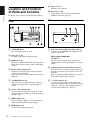
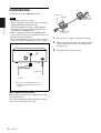
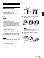
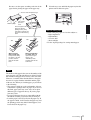
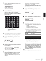
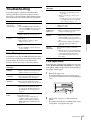
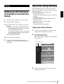
2-653-913-13(1)
DICOM Color
Printer
Instructions for Use Page 2
Setup Manual Page 24
This manual is comprised of the Instructions for Use and the Setup Manual.
The Instructions for Use gives the information on how to use the printer for the
routine work.
The Setup Manual gives the system administrator the information needed to setup
the printer and connect it to the network.
UP-D77MD
© 2005 Sony Corporation
Owner's Record
For the customers in Canada
The model and serial numbers are located at the rear.
Record these numbers in the space provided below.
Refer to these numbers whenever you call upon your
Sony dealer regarding this product.
This unit has been certified according to Standard CSA
C22.2 No.601.1.
Model No. ____________________
Serial No. ____________________
WARNING
To reduce the risk of fire or electric shock, do
not expose this apparatus to rain or moisture.
To avoid electrical shock, do not open the
cabinet. Refer servicing to qualified personnel
only.
For the customers in the U.S.A and
Canada
Model UP-D77MD is Non-Patient Equipment.
This unit can not be used in the vicinity of patients.
* Patient Vicinity
m
83 t)
R fee
(6
1.
THIS APPARATUS MUST BE EARTHED.
To disconnect the main power, unplug the AC
IN connector.
This symbol indicates the equipotential
terminal which brings the various parts of a
system to the same potential.
For the customers in the U.S.A.
This equipment has been tested and found to comply
with the limits for a Class A digital device, pursuant to
Part 15 of the FCC Rules. These limits are designed to
provide reasonable protection against harmful
interference when the equipment is operated in a
commercial environment. This equipment generates,
uses, and can radiate radio frequency energy and, if not
installed and used in accordance with the instruction
manual, may cause harmful interference to radio
communications. Operation of this equipment in a
residential area is likely to cause harmful interference in
which case the user will be required to correct the
interference at his own expense.
You are cautioned that any changes or modifications not
expressly approved in this manual could void your
authority to operate this equipment.
All interface cables used to connect peripherals must be
shielded in order to comply with the limits for a digital
device pursuant to Subpart B of Part 15 of FCC Rules.
2
When you use this product connected to 240 V single
phase, be sure to connect this product to a center tapped
circuit.
Important safeguards/notices for use in
the medical environments
1. All the equipments connected to this unit shall be
certified according to Standard IEC60601-1,
IEC60950-1, IEC60065 or other IEC/ISO Standards
applicable to the equipments.
2. When this unit is used together with other equipment
in the patient area*, the equipment shall be either
powered by an isolation transformer or connected via
an additional protective earth terminal to system
ground unless it is certified according to Standard
IEC60601-1.
* Patient Area
5m
1.
R
3. The leakage current could increase when connected
to other equipment.
4. This equipment generates, uses, and can radiate radio
frequency energy. If it is not installed and used in
accordance with the instruction manual, it may cause
interference to other equipment. If this unit causes
interference (which can be determined by
unplugging the power cord from the unit), try these
measures: Relocate the unit with respect to the
susceptible equipment. Plug this unit and the
susceptible equipment into different branch circuit.
Consult your dealer. (According to standard
EN60601-1-2 and CISPR11, Class B, Group 1)
Caution
When you dispose of the unit or accessories, you must
obey the law in the relative area or country and the
regulation in the relative hospital.
Warning on power connection
Use a proper power cord for your local power supply.
1. Use the approved Power Cord (3-core mains lead) /
Appliance Connector / Plug with earthing-contacts
that conforms to the safety regulations of each
country if applicable.
2. Use the Power Cord (3-core mains lead) / Appliance
Connector /Plug conforming to the proper ratings
(Voltage, Ampere).
If you have questions on the use of the above Power
Cord/Appliance Connector/Plug, please consult a
qualified service personnel.
Warning on power connection for
medical use
Please use the following power supply cord.
With connectors (plug or female) and cord types other
than those indicated in this table, use the power supply
cord that is approved for use in your area.
United States
Canada
Plug Type
HOSPITAL GRADE*
HOSPITAL GRADE*
Female end
E62405, E35708
LR53182, LL022442,
LL088408
Cord type
E159216, E35496
Min.Type SJT
Min.18 AWG
LL112007-1, LL20262,
LL32121, LL84494
Min.Type SJT
Min.18AWG
Minimum cord set
rating
10A/125V
10A/125V
Safety approval
UL Listed
CSA
*Note: Grounding reliability can only be achieved when the equipment is connected to an equivalent receptacle marked ‘Hospital Only’
or ‘Hospital Grade’.
For Customers in Taiwan only
3
Instructions for Use
Table of Contents
Introduction
Features ...................................................................5
System Configuration ............................................5
Location and Function of Parts and Controls .....6
Front ....................................................................6
Rear .....................................................................6
Preparation
Supplied Accessories ..............................................7
Assembly .................................................................7
Connections ............................................................8
Operation
Before Printing .......................................................9
Loading an Ink Ribbon Cassette .........................9
Loading the Paper .............................................10
Printing .................................................................12
Starting to Print .................................................12
Making Printouts with the Desired Color .........12
Adjusting Printouts ..............................................13
Adjusting Gray ..................................................13
Adjusting the Color ...........................................14
Miscellaneous
Precautions ...........................................................17
Safety ................................................................17
Installation ........................................................17
On Transportation .............................................17
Cleaning ............................................................17
Ink Ribbon and paper .........................................19
Specifications ........................................................20
Troubleshooting ....................................................21
Error Messages .................................................21
If the Paper Jams ...............................................21
Index ......................................................................23
Introduction
The UP-D77MD DICOM Color Printer is a dye
sublimation thermal transfer printer designed to
reproduces image data in DICOM format sent via the
network.
The UP-D77MD has the following functions’
• Equipped with DICOM (Digital Imaging and
Communications in Medicine) features
The DICOM portion of the unit receives image data in
DICOM format sent from the modality via the
network, processes them in A4 size paper either by
enlarging or reducing them.
• High quality and high print resolution
The unit allows you to print out in full color (256
gradations process for each color) and in highresolution print mode (300 dpi).
The system allows you to make printouts of the data in
DICOM format, sent from image diagnosis equipment
such as CTs, NMs.
The following shows a system configuration example.
Personal computer for
managing the system
Introduction
Features
System Configuration
DICOM server
DICOM LAN network
Modality
Image diagnosis
equipment and so on
Modality
Image diagnosis
equipment and so on
UP-D77MD
Features / System Configuration
5
Location and Function
of Parts and Controls
I Paper cover (7)
Printouts are ejected here.
Introduction
For details, refer to the pages indicated in parentheses.
J Paper tray (7, 10)
Load paper here. Press the point marked with
PUSH to remove the paper tray.
Front
Rear
A !POWER switch
Press to turn the printer on or off.
A Network connector (RJ-45 modular jack) (8)
Conforms to the 100BASE-TX standard. Used to
connect to the LAN.
B Fan cover (7, 18)
Provided to prevent the printer from dust.
C Ribbon door (9)
Pull the tab (marked with PULL) on the top on the
ribbon door to open it when loading an ink ribbon
cassette.
D Printer window display (12)
Displays the status messages. In menu operation,
menu items are displayed.
If an error occurs, a corresponding error message is
displayed.
E ALARM indicator (21)
Lights in orange when the ink ribbon or paper is
exhausted, the paper jams, or another problem
occurs.
F Cursor control buttons (13)
Use these buttons to increase or decrease a value
and level shown on the menu, or scroll up and down
through a menu.
G MENU button (13)
Press this button to display or close the printout
adjust menu in the printer window display.
H EXEC button (13)
Use this button in menu operation.
6
Location and Function of Parts and Controls
When using a LAN cable:
CAUTION
For safety, do not connect to the connector for
peripheral device wiring that might have excessive
voltage.
B
Equipotential ground terminal connector
Used to connect to a ground (equipotential) plug to
bring the various parts of the system to the same
potential.
Refer to “Important safeguards/notices for use in
the medical environments” on page 2.
C -AC IN connector (8)
Use a proper power cord for your local power
supply (not supplied).Refer to “Warning on power
connection” on page 3 and “Warning on power
connection for medical use” on page 3.
Preparation
Assembly
Mount the supplied ink ribbon holder, paper tray, paper
cover, bottom cover and fan cover.
Supplied Accessories
This printer is packed together with the following
accessories. Check that nothing is missing from your
package.
Paper cover (1)
You cannot mount the ink ribbon holder when the
thermal head is locked.
Before assembling, turn on the power of the printer. The
thermal head is unlocked and you can mount the ink
ribbon holder. (page 9)
Preparation
Paper tray (1)
Note
Paper cover
Ink ribbon holder (1)
Bottom cover (1)
Fan cover
with a filter
Bottom
cover
Ink ribbon holder
Paper tray
Fan cover with a filter (1)
Fan cover
Filter
Thermal Head Cleaning Kit (1)
Ferrite core (2)
CD-ROM (1)
Before Using this Printer (1)
Note
Retain the original carton and packing materials in case
you have to transport this unit in the future.
Note on using the UP-D77MD
The unit is equipped with a hard disk which is used as
the system region and for temporarily storing the image
data. The hard disk is susceptible to shock, vibration,
and so on.
Pay attention to the following when using the unit:
• Do not subject the printer to shock.
• Do not use the printer in a place that vibrates or is
unstable.
• Do not move the printer while it is turned on.
• Do not turn the printer off while printing.
• Do not subject the printer to wide or sudden changes
in temperature.
Note that the UP-D77MD may not be able to start, if the
hard disk is damaged for some reason.
Supplied Accessories / Assembly
7
Connections
Connect the unit to the 100BASE-TX LAN.
Ferrite core
Stoppers
Notes
Preparation
• Connect the AC power cord last.
• Before connecting to the LAN, be sure to set up the
required IP address and sub-net mask.
For detailed information, refer to “Setup Manual”
provided in the latter part of this manual, and also
consult the system administrator.
• Before connecting the unit using a 100BASE-TX
cable, attach the ferrite cores provided to both ends of
the cable for noise prevention.
For detailed information on how to attach the ferrite
cores, see “How to attach the ferrite cores” on page 8.
to the network connector
to- AC IN
100BASE-TX cable a)
Power cord
to the LAN
a) Be sure to use a network cable of less
than 30 m in length, and rated more than
category 5.
How to attach the ferrite cores
Before using the unit, attach the supplied ferrite cores
for noise prevention.
To confirm to radiation standards, attach the supplied
ferrite cores to both ends of the cable.
8
Connections
About 13 mm
(1/2 inch)
About 13 mm
(1/2 inch)
1
Release the two stoppers to open the ferrite core.
2
Make a loop at the end of the cable about 13 mm (1/
2 inch) away from the connector, and then attach
the ferrite cores.
3
Close the ferrite core until it clicks.
Operation
1
Open the ribbon door by pulling the tab on the
ribbon door and marked with PULL.
2
Remove the ink ribbon cassette by pressing the
EJECT button.
The ink ribbon cassette pops out.
Before Printing
Notes
• When replacing the ink ribbon or paper, do not turn off
the power. Turning off the power will cause the image
stored in the memory to be lost.
• Use the ink ribbon suitable for the type of print
material. Before attempting to load an ink ribbon,
make sure that the combination of the ribbon and
paper is compatible. (See “Ink Ribbon and paper” on
page 19.)
• Use only ink ribbon and paper designed for use
with this printer. Failing to do so is likely to result
in unsatisfactory printing or malfunctions. (See
“Ink Ribbon and paper” on page 19.)
Loading an Ink Ribbon Cassette
Load the ink ribbon to the supplied ink ribbon holder,
and load the ink ribbon cassette (referring to the ink
ribbon holder loaded with the ink ribbon) to the printer’s
ribbon compartment.
Operation
This section describes the operations that must be
performed prior to starting printing. This explanation
assumes that the printer has already been installed and
that all connections have been made.
• Loading an ink ribbon cassette (on this page)
• Loading the paper (page 10)
Once these operations have been completed, there
should be no need to perform them again during routine
printing.
Note
Never put your hand into the ink ribbon
compartment. The thermal head becomes very hot.
You may burn yourself if you touch it.
3
Detach the used ink ribbon from the ink ribbon
holder.
Notes
• When you use the printer at the first time, the thermal
head was locked at the factory. Turn on the printer first
to unlock the thermal head, then start to load an ink
ribbon cassette.
• Once an ink ribbon has been completely used, replace
it. Ink ribbons are not reusable.
• Do not rewind the ink ribbon for reuse.
• Do not touch the ink ribbon or place it in a dusty
location. Finger prints or dust on ink ribbon will result
in imperfect printing.
1 Remove the spool
with the ink ribbon,
while pressing in
the arrow
direction.
2 Remove the
other spool.
Before Printing
9
4
Load the ink ribbon to ink ribbon holder.
1 Load the spool holding the ink ribbon into the right-hand
part of the holder, while pressing in the arrow direction.
If your ink ribbon should tear
Repair the tear with transparent tape. There should be no
problem with using the remaining portion of the ribbon.
Transparent
tape
Remove any
slack.
Ink ribbon holder
(supplied)
2 Fit the other
spool into the
left-hand part of
the holder.
Bar code
Operation
Notes When storing ink ribbons
5
Remove any slack from the ink ribbon.
If the ribbon is left slack, it may be crumpled and
damaged when inserted.
“Start” position
marker
• Avoid placing the ink ribbon in a location subject to:
– high temperatures
– high humidity
– excessive dust
– direct sunlight
• Store partially used ink ribbon in its original package.
Loading the Paper
Wind the spool until the
“Start” position marker faces
upward.
6
Insert the ink ribbon cassette firmly until it stops.
Load the paper by the following procedure. Be careful
not to touch the printing surface of the paper.
Note
When loading the paper, do not turn off the power. If you
turn off the power, the image data stored in the memory
will be lost.
1
Press PUSH on the paper tray.
The paper tray is ejected.
SONY mark faces forwards.
Remove the printing surface
protection sheet, if any.
7
Close the ribbon door.
Paper tray
2
10
Before Printing
Open the tray cover and place the paper in the paper
tray.
Be sure to set the spacer according to the size of the
paper before placing the paper in the paper tray.
3
Close the tray cover and slide the paper tray into the
printer until it clicks into place.
Reverse side with printed logos
Riffle the paper.
Print surface
protection
sheet
Place the paper in the
paper tray with the
printing surface (shiny
side with no legends) and
its protection sheet facing
down.
When using the
UPC-770 (A4 size):
Pull up the tab, bring
the spacer to the “A4”
position, and then
push the tab down
there.
Tab
• Avoid storing the paper in a location subject to:
– high temperatures
– high humidity
– excessive dust
– direct sunlight
• Use the original package for storing unused paper.
Operation
Tab
Notes on storing paper
When using the UPC771 (letter size): Pull
up the tab, bring the
spacer to the
“LETTER” position,
and then push the tab
down there.
Notes
The number of the paper is the same as the number of the
paper that one roll of the ink ribbon can afford. Usually
the ink ribbon and paper have run out at the same time.
However, even when either the ink ribbon or the paper
has run out, replace both the ink ribbon and the paper
with new ones. When you load the paper, pay attentions
to the following.
• The paper tray holds up to the total number of sheets
contained in a package sheets of paper. If you exceed
this limit, paper jams may occur. Also, do not place
different types of paper in the tray. If you do, paper
jams may occur.
• If you load the paper that is not compatible with the
ink ribbon used, the gray balance may be changed.
• Load the paper so that it lays flat in the paper tray. If
the paper is curled, it will overflow the paper tray and
the printing position may shift. If this happens, load
fewer sheets in the paper tray.
Before Printing
11
2 The printer starts printing and the following
message appears.
Printing
Before printing
• Ensure that the printer is properly connected (page 8).
• Ensure that the combination of the ink ribbon and
paper is correct (pages 9 and 10).
• Ensure that the ink ribbon cassette and paper are
properly loaded (page 19).
• Ensure that the desired color is loaded (page 12)
Starting to Print
Operation
Printer window display
1
1
3 The printing time depends on the size of image,
type of ribbon, and/or resolution mode. It takes
about 85 seconds (A4 size paper) for a printout
to emerge from the paper outlet.
Once printing has been completed, the printer
returns to standby status.
Paper outlet
Notes
Turn on the power of the printer.
While the printer is starting up, “INITIALIZING”
is displayed.
After about two minutes, the following message
appears in the printer window display, and the
printer is in standby status. While “READY” is
displayed, the printer is in standby mode.
The size of the paper
being loaded
2
Color indication changes
as color printing
proceeds:
Laminate printing:
Starting t YELLOW t
MAGENTA t CYAN t
LAMI t Finishing
Send the image data from the computer (modality)
to the printer.
1 While the printer is receiving the image data
from the computer, the following message
appears:
• Do not pull the paper out until the printer finishes
printing.
• To prevent paper jamming, do not allow more than
20 printouts on the paper cover.
If the printer does not print
The printer will fail to print when an error message is
displayed in the printer window display. Take remedies
according to explanation of the message given in “Error
Messages” on page 21.
Notes on storing your printouts
• Avoid storing the printout in a location subject to high
temperatures, high humidity, excessive dust, and
direct sunlight.
• Do not stick tape on a printout. Also avoid leaving a
plastic eraser on a printout or placing a printout in
contact with materials which contain plasticizer
(under a desk mat, for example).
• Do not allow alcohol or other volatile organic solvents
to come into contact with the printouts.
Making Printouts with the Desired
Color
You can register the desired color of printouts as a user
setting. The printer allows you to register up to 9 sets of
12
Printing
settings. By selecting a desired user set number, you can
make printouts in the desired color.
4
Printer window display
3
2
You can adjust the gray first, then you can adjust colors
based on the adjusted gray. You can store up to 9 color
settings as a user set. The printer retains these settings
even if you turn off the power. Thus, different operators
can make printouts with different color settings by
loading the appropriate user set. If the data of the loaded
user set is modified, the printer operates according to the
modified data. In such a case, the modified data remains
effective until another user set is loaded, even if you turn
off the power.
Adjusting Gray
Press the MENU button.
“INFORMATION” appears.
3,4
Printer window display
2
Operation
1
1 5
Adjusting Printouts
2,4
Press the g button.
“COLOR ADJUST” appears.
3
Press the f button.
“LOAD USER X” appears.
4
Select the desired user preset number by pressing
the G or g button.
1
Make a printout of image data which has a large
amount of gray parts.
It is recommended that you make a printout of the
full-size picture. If you make a printout composed
of multiple reduced images, it may be difficult to
check the color.
If you are satisfied with the gray in that printout, go
to “Adjusting the Color” on page 14.
If you wish to adjust the gray further, proceed as
follows.
2
Press the MENU button.
“INFORMATION” appears.
3
Press the g button.
“COLOR ADJUST” appears.
Display the desired user
preset number by
pressing the G or g
button.
5
Press the EXEC button.
The user setting selected in step 4 is loaded.
Adjusting Printouts
13
4
Adjust the gray.
When you adjust the gray, the color intensity is also
adjusted. However, adjust the gray first, then adjust
the desired color.
To adjust the tone (density gradation)
Item to be
adjusted
Adjustment
GAMMA
To adjust the half tone of printouts
To adjust the sharpness
Item to be
adjusted
Adjustment
SHARPNESS
To adjust the sharpness of printouts
The sharpness can be adjusted between 0 to 3.
Operation
1 Select the item for adjustment by using the F or
f button.
f: Scrolls up to the next item.
F: Scrolls down to the previous item.
2 Adjust the level by pressing the G or g button.
You can adjust the color level for CYN-RED,
MAG-GRN, YEL-BLU, DARK and LIGHT
for the tone, and GAMMA for the half tone
between –32 to +32. The value 0 is the standard
level.
g: Increases the level.
G: Decreases the level.
When you keep the button pressed, the number
changes quickly.
To adjust the color intensity (RED/
GREEN/BLUE)
Item to be
adjusted
Adjustment
Button to be
pressed
CYN-RED
To make an image
reddish
g
To make an image
cyan
G
To make an image
greenish
g
To make an image
magenta (pink)
G
To make an image
bluish
g
To make an image
yellowish
G
MAG-GRN
YEL-BLU
Example: To set CYN-RED to +20 toward
RED
Press the g button until “+20” appears.
When you keep the button pressed, the number
changes quickly.
Press the g button until
“+20” appears.
3 After finishing the adjustment of 1 and 2,
press the MENU button to exit the adjustment
mode.
4 Make a printout again.
Repeat your adjustments until the desired gray
level is obtained.
When the desired gray is obtained, go to the
next color adjustment.
Adjusting the Color
After finishing the gray, continue adjustment for the
color.
Before starting the color adjustment, make a full-size
printout of the image which has the color you want to
adjust.
1,4,5,7,8,9,10
9,11
Printer window display
To adjust the contrast
Item to be
adjusted
Adjustment
DARK
To adjust the dark area of an image
LIGHT
To adjust the light area of an image
2,6,10
14
Adjusting Printouts
1
2
Display “PRINT PATCH” by pressing the F or f
button in menu mode.
When you are satisfied with the color balance
selected in step 3, go to step 10.
If you are not satisfied with the color and want to
adjust the hue, saturation, and value of the color, go
to the next step.
7
Display “ADVANCED” by pressing the F or f
button.
8
Display “STANDARD” by pressing the g button.
9
Adjust the hue, saturation, and value of the color.
Press the EXEC button.
25 identical images of the image last printed are
printed on a sheet of paper as a patch print.
Each image has a different color balance, but they
have the same gray.
Operation
1 Select the item to be adjusted by using the F or
f button.
f: Scrolls up to the next item.
F: Scrolls down to the previous item.
Image whose gray and color
adjusted in “Adjusting Gray” on
page 13
3
4
Select the image which has the best color balance
among the 25 images, by looking at the printout.
Display “SEL PATCH” by pressing the F or f
button.
2 Adjust the level by pressing the G or g button.
You can adjust each item between –32 to +32.
The value 0 is the standard level.
Item to be
adjusted
Adjustment
HUE
To adjust the hue of the color
SATURATION
To adjust the saturation of the color
VALUE
To adjust the value of the color
3 After adjusting the hue, saturation, and value of
the color, press the MENU button to exit the
adjustment mode, and make a printout to
confirm the results of the adjustment.
5
Display the number selected in step 3 by pressing
the G or g button.
Keep pressing the G or
g button until the
number selected in step
3 is displayed.
When you are not satisfied with the results
Reset the printer to menu mode again, following the
procedure in steps 2 and 3 in “Adjusting Gray” on
page 13. The printer retains those adjusted values,
even if you turn off the power. Proceed as follows
to save them as a user set.
10 Store the adjusted values of the color as a user set.
6
Press the EXEC button.
The color is determined according to the patch
number selected in step 3. However, the gray
adjusted in “Adjusting Gray” on page 13 is not
changed.
Adjusting Printouts
15
1 In menu mode, display “SAVE /USER X/” by
pressing the F or f button.
2 Display the desired user set number by pressing
the G or g button.
Keep pressing the G or
g button until the
desired user number is
displayed.
Operation
3 Press the EXEC button.
All values adjusted in “Adjusting Gray” on
page 13 and here, “Adjusting the Color,” are
registered in the user set number selected in
step 2.
The printer operates according to this
registered value set unless you load another
user set. Also, if you modify the settings, the
modified values remain effective until another
user set is loaded, even if you turn off the
power.
11 Press the MENU button to exit menu mode for
adjusting gray and color.
The printer returns to standby status and “READY”
appears in the printer window display.
16
Adjusting Printouts
Miscellaneous
Precautions
Safety
Installation
• Avoid placing the unit in a location subject to:
– mechanical vibration
– high humidity
– excessive dust
– direct or excessive sunlight
– extremely high or low temperatures
• Ventilation holes are provided on the both sides and
the rear of the unit to prevent the unit from
overheating. Be careful not to obstruct them with other
objects or by covering the unit with a cloth etc.
On condensation
• If the printer is subjected to wide and sudden changes
in temperature, such as when it is moved from a cold
room to a warm room or when it is left in a room with
a heater that tends to produce quantities of moisture,
condensation may form inside the printer. In such
cases the printer will probably not work properly, and
may even develop a fault if you persist in using it. If
moisture condensation forms, turn off the power and
leave the printer standing for at least one hour.
• If the printing pack is subjected to wide and sudden
changes in temperature, condensation may form on
the ink ribbon or paper inside. This will cause the
On Transportation
Do not transport the printer with the supplied
accessories. Doing so may cause malfunction.
1
Remove the ink ribbon cassette and the paper tray.
2
Lock the thermal head.
1 Turn on the power of the printer.
2 Press the MENU, G and g buttons together and
hold them for 2 seconds.
3 Turn off the power of the printer.
Miscellaneous
• Operate the printer using the power source specified in
“Specifications” (page 20).
• Be careful not to damage the power cable by placing
or dropping heavy objects on it; it is dangerous to use
the unit with a damaged power cable.
• If you do not intend to use the unit for a long time,
disconnect the power cable.
• Unplug the power cable by grasping the plug, not the
cable itself.
• Do not disassemble the unit. There is a danger of
electric shock from the internal parts.
• Be careful not to spill water or other liquids on the
unit, or to allow combustible or metallic material to
enter the cabinet. If used with foreign matter in the
cabinet, the unit is liable to fail, or present a risk of fire
or electric shock.
• If the unit malfunctions or if a foreign body falls into
the cabinet, disconnect the power immediately and
consult your Sony service facility or your Sony dealer.
printer to malfunction. Also if the printing pack is
used in this state, spots are likely to appear on the
printout.
• To store a half-used printing pack, replace it in its
original packing and reseal the package. If possible,
keep the sealed printing pack in a cool, dark location.
To subsequently use the printing pack, place it, in its
sealed package, in a warm room for several hours.
Doing so prevents condensation from forming when
the printing pack is removed from its package.
Note
Never put your hand into the ink ribbon compartment,
when locking the thermal head. Doing so may cause
injury to your hand because it may be caught by the
thermal head.
To unlock the thermal head
Turn on the power of the printer again. The thermal head
moves and you can load the ink ribbon cassette again.
Cleaning
Note
Be sure to turn off the power of the printer before
cleaning it. The ink ribbon and paper roll removed
When the cabinet becomes dirty
Clean the cabinet, panel and controls with a soft dry
cloth, or a soft cloth lightly moistened with a mild
detergent solution.
Do not use any type of solvent, such as alcohol or
benzine or chemical cloth, which may damage the
finish.
Cleaning the filter
Ventilation holes are provided to prevent the unit from
overheating on the both sides and the rear of the printer.
When the message “CLEAN FAN FILTER” appears on
the printer widow display, the filter of the ventilation
holes on the left side has become dirty.
Precautions
17
To clean the filter, proceed as follows.
1
Remove the fan cover, then filter.
Filter
Use the black tip in the following cases
• When a scratch appears only on the printout, but no
scratches appear on the spaces around the picture.
• When the use of the white tip has no effect.
• Periodic head cleaning
We recommend use of the black tip every month
(or every 500 sheets of printout) to keep the
thermal head clean.
Store the tips by inserting the white one into the cleaning
tip hole on the holder, and the black one into the spare
tip hole.
Fan cover
2
Cleaning tip hole
Clean the filter using the vacuum cleaner and the
like.
Spare tip hole
Notes
Miscellaneous
• Be careful that the filter will be caught in the
cleaner.
• Do not rub the net of the filter strongly.
3
Attaching the tips on the cleaning kit holder
Reset the filter and the fan cover on the side panel
as they were.
1
Align the pronged parts of the tip with the cross
notches of the hole.
Cross notches
Pronged parts
2
Cleaning the thermal head
You should clean the thermal head in the following
cases:
• When the vertical white stripe appears on the printout.
• When the scratch appears on the printout.
How to use the white tip and black tip
When using the white tip, the sponge roller wipes off the
dust on the thermal head.
When using the black tip, the polishing material on the
sponge roller scrapes off the dust on the head.
Use the white tip in the following cases
• When a vertical white stripe appears on the printout
because of dirt on the thermal head.
• Ordinary head cleaning for preventing accumulation
of dirt on the head
18
Precautions
Insert the tip fully until it stops with a click.
Turning the tip to keep the cleaning effect
The cleaning effects decreases when the tip is used the
following number of times:
White tip: Cleaning about 30 times
Black tip: Cleaning one time
To regain the original cleaning effect, reinsert the tip, as
shown below, so that you can clean the head with the
unused surface of the tip.
Pull out the tip, turn it 90°,
then reinsert it.
One tip provides four new surfaces. After using all
unused surfaces, exchange the tip for a new one.
The cleaning tip set is available using part number A8279-104 (at a charge).
Cleaning of the thermal head
To clean the thermal head, proceed as follows:
1
Remove the ink ribbon cassette from the printer.
2
Attach the cleaning tip to the cleaning tip holder,
and install the cleaning tip holder in the printer.
The cleaning tip holder can be mounted in the same
way as that of the ink ribbon cassette.
3
Insert the cleaning tip holder fully until it stops,
then pull the holder out until the open window of
the holder fully appears. Repeat the inserting/
pulling-out of the holder about three times.
Open window
Ink Ribbon and paper
You need paper and ink ribbon cassette for printing.
(“Ink ribbon cassette” stands for the supplied ink ribbon
holder loaded with ink ribbon.) Use the ink ribbon and
paper contained in the same package. If the printer
detects an incompatible combination, an error message
appears in the printer window display and you cannot
make printouts.
Self-laminating Color Printing Pack UPC-770
Contains an ink ribbon and paper for automatic laminate
coating.
Color ink ribbon 1 roll
A4 size paper 72 sheets
Miscellaneous
Self-laminating Color Printing Pack UPC-771
Contains an ink ribbon and paper for automatic laminate
coating.
Color ink ribbon 1 roll
Letter size paper 72 sheets
Notes
Thermal head cleaning is finished.
4
• Use only ink ribbon and paper for this printer. If you
use a different type, the printer may not print properly
or malfunction.
• Ink ribbon and paper are not reusable. After you finish
with them, replace them with new ones.
Remove the cleaning tip holder from the printer,
and remount the ink ribbon cassette in the printer.
Notes
• Don’t moisten the tip with the cleaning liquid or water.
A moistened tip may deteriorate the performance of
the thermal head.
• Especially when using the black tip, be careful not to
insert/pull-out the holder too many times at one
cleaning. The lifespan of the head may be decreased.
• Be careful not to swallow the cleaning tips. Store them
out of the reach of children.
Ink Ribbon and paper
19
Protection against harmful ingress of
water: Ordinary
Degree of safety in the presence of
flammable anesthetics or oxygen:
Not suitable for use in the presence
of flammable anesthetics or oxygen
Mode of operation:
Continuous
Specifications
Miscellaneous
Power requirements
100 – 240 V AC, 50/60Hz
Input current
3.5 A to 1.5 A
Operating temperature
10°C to 30°C (50°F to 86°F)
Operating humidity
20% to 80% (no condensation allowed)
Storage and transport temperature
–20°C to +60°C (–4°F to +140°F)
Storage and transport humidity
20% to 90% (no condensation allowed)
Dimensions
Approx. 493.8 × 176 × 468.8 mm
(w/h/d)
(19 ½ × 7 × 18 ½ inches)
Mass
Approx. 21 kg. (46 lb 5 Oz)
Printing system
Dye transfer sublimation thermal
printing
Thermal head 2,560 elements, 11.8 dot/mm (300dpi)
Gradations
256 levels each for yellow, magenta
and cyan
Picture size
Maximum
Letter size: 254.0 × 203.2 mm (w/h)
(10 × 8 inches)
A4 size: 271.6 × 203.2 mm (w/h)
(10 ¾ × 8 inches)
Picture elements
Maximum
Letter size: 3,000 × 2,400 dots (w/h)
A4 size: 3,208 × 2,400 dots (w/h)
Printing time Approx. 85 seconds per page (A4 size)
Digital interface
Network port × 1
(RJ-45 Modular jack), Conforming
to 100BASE-TX standard
Accessories supplied
Ink ribbon holder (1)
Paper tray (1)
Paper cover (1)
Fan cover (1)
Bottom cover (1)
Ferrite core (2)
Thermal Head Cleaning Kit (1)
CD-ROM (1)
Before Using this Printer (1)
Optional accessories
Self-Laminating Color Printing Pack
UPC-770
Self-Laminating Color Printing Pack
UPC-771
Medical Specifications
Protection against electric shock:
Class I
20
Specifications
Design and specifications are subject to change without
notice.
SOP and Meta SOP Classes
SOP Class Name
SOP Class UID
Verification SOP Class
1.2.840.10008.1.1
Basic Color Print Management Meta
SOP Class
1.2.840.10008.5.1.1.18
Basic Film Session SOP Class
1.2.840.10008.5.1.1.1
Basic Film Box SOP Class
1.2.840.10008.5.1.1.2
Basic Color Image Box SOP
Class
1.2.840.10008.5.1.1.4.1
Print SOP Class
1.2.840.10008.5.1.1.16
Basic Annotation Box SOP Class
1.2.840.10008.5.1.1.15
Troubleshooting
Possible causes and remedies
NO PAPER
• The paper has run out.
tLoad the paper into the paper tray.
(page 10)
• The spacer of the paper tray is not set
correctly.
tSet the spacer to the correct position
according to the size of the currently
used printing pack. (page 11)
PLEASE WAIT
The printer is carrying out processing
which requires time.
tWait for a while.
REMOVE
PAPER AND
PRESS [g]
The paper has jammed.
tRemove jammed paper from the printer
and press g button. (page 21)
RIBBON
ERROR
The ink ribbon develops some trouble.
tEnsure that the ink ribbon does not tear
and the ink ribbon cassette and paper
tray are loaded properly. (pages 7, 9 and
10)
tCheck that the currently used printing
pack is the UPC-770 or UPC-771.
(page 19)
MECHA
TROUBLE
The mechanical trouble occurs in the
printer.
tTurn off the power once and then turn it
on. If the message will still remain in the
printer window display, turn off the
power immediately and contact your
Sony dealer.
If a problem appears, check the following trouble
shooting guide first and perform whatever action is
necessary to solve the problem. If the problem persists,
turn off the printer and consult with your Sony dealer.
Symptom
Possible causes and remedies
Nothing appears
in the printer
window display.
The POWER switch of the printer is not set
to ON.
tSet the POWER switch of the printer to
ON. If the POWER switch is set to ON,
once set it to OFF, then to ON again.
(page 6)
Connections may not be correct.
tMake connections correctly. (page 8)
The printer does
not print.
An error message appears on the printer
window display.
tTake remedies according to “Error
Messages.”(page 21).
An ink ribbon cassette and paper are not
loaded.
tLoad an ink ribbon cassette and paper.
(pages 9 and 10)
Error Messages
If a problem occurs, the ALARM indicator lights and an
error message stating the problem appears in the printer
window display. Note the message and perform
whatever action is necessary to solve the problem.
Error
messages
Possible causes and remedies
END OF
RIBBON
The ink ribbon has been completely used.
tReplace with the new ink ribbon. (Ink
ribbons cannot be reused.) (page 9)
HEAD IN
COOLING
The thermal head has overheated.
tLeave the printer until the head cools
down and this message disappears.
HEAD IN
HEATING
The thermal head is warming up.
tLeave the printer until the head has
warmed up and this message disappears.
NO RIBBON
Ink ribbon cassette is not fitted properly.
tEnsure that the ink ribbon is loaded
properly in the ink ribbon holder, and
the ink ribbon cassette in the printer.
(page 9)
NO IMAGE
DATA
No image data for the patch print is stored
in the printer memory.
tTransfer the image data from your
computer to make a printout before
making a patch print by pressing the
EXEC button in the adjustment mode.
(page 14)
Miscellaneous
Error
messages
If the Paper Jams
If the paper jams, printing stops and the error message
stating “REMOVE PAPER AND PRESS [g]” appears
on the printer window display. Follow the steps below to
remove the jammed paper.
1
Remove the paper cover.
If any printouts have been ejected on the paper
cover, remove them first before removing the paper
cover.
2
Check where any paper is jammed inside the
printer.
If you find a jammed sheet around the paper outlet,
slowly pull it out starlight to the right.
Troubleshooting
21
If you find a jammed sheet on the way inside the
printer, slowly pull it out to the right. If the tray
cover is in the way, remove it.
If the tray cover is in the way, remove
it by lifting it up 1, and then pulling it
out to the direction of arrow 2.
Press PUSH on the paper tray.
The paper tray pops out.
4
Remove the bottom cover.
5
Check whether any paper is found on the bottom of
the printer. If you find one, remove it.
6
Ensure that the paper is properly loaded.
Discard the sheets removed in steps 2 and 5
Miscellaneous
3
22
Troubleshooting
7
Re-insert the removed bottom cover, paper tray,
tray cover and/or paper cover into the printer.
8
Press the g button.
The error message disappears and the printer
returns to the standby status.
Index
M
Mounting paper tray and cover 7
P
Accessories supplied 7, 20
Assembly 7
Paper
adding paper 11
If paper jams 21
Loading 10
Paper cover 7
Paper jams 21
Paper outlet 12
Paper tray 7, 10, 11
Part Names and Functions
Front 6
Rear 6
Picture size 20
Power requirements 20
Precautions
Condensation 17
Installation 17
Safety 17
Transportation 17
Print paper
Notes on storing 11
Printer window display 12
Printing 12
If the printer does not print 12
Printing pack 19
Printing time 20
Printouts 12
Notes on storing 12
B
Bar codes 10
Bottom cover 7, 22
C
Cleaning
Cabinet 17
Filter 17
Thermal head 18
Color printing pack 19
Combination of ink ribbon and paper
19
Connections 8
E
EJECT button 9
Error messages 21
F
Fan 7, 17
Features 5
Filter 7, 17
I
Image data 12
Ink ribbon 9
Ink ribbon and paper
usable printing pack 19
Ink ribbon cassette
Bar codes 10
If your ink ribbon should tear 10
Loading 9
Notes on storing 10
Removing any slack 10
Start position marker 10
Ink ribbon holder 7, 9
Introduction 5
L
LAMINATE
printing pack 19
Loading the paper 10
Miscellaneous
A
R
Ribbon and paper 19
Ribbon door 9
S
SOP and Meta SOP classes 20
Specifications 20
Standby status 12
Start position marker 10
Supplied accessories 7
Bottom cover 7
CD-ROM 7
Fan cover 7
ferrite cores 8
Ink ribbon holder 7
Paper cover 7
Paper tray 7
System configuration 5
T
Troubleshooting 21
Index
23
Setup Manual
Table of Contents
Preparation
Overview ...............................................................25
Requirements ........................................................25
IP Address .............................................................26
Setup
Setting up the Personal Computer to be Used for
Setup ......................................................................27
About the Setup Window ....................................27
Opening the Setup Window ..............................27
Components of Pages ........................................28
Setup of the Unit ...................................................30
Setup of E-Mail ....................................................30
Confirmation After Setup ...................................31
Preparation
This setup manual gives the system administrator
information needed to setup the unit on the network or
to reset the IP address and so on.
This setup manual describes the preparation for the
setup, gives an overview of the setup window, explains
how to perform setup related to IP address and so on,
and explains how to setup an E-mail warning to tell
automatically when any trouble occurs.
The following hardware and Web browser software are
necessary to perform the setup.
• Computer: A computer which can be connected to the
network connector of the UP-D77MD
• Operating system a): Microsoft Windows 95,
Windows 98, Windows NT 4.0, Windows 2000, or
Windows XP
• LAN cable: 100BASE-TX cross cable
• Web browser software: Internet Explorer a) 5.5 or
later, or Netscape a) 4 or later
Set the Web browser software as follows:
No proxy
A blank page is opened when the Web browser
software is started.
Preparation
Overview
Requirements
a) Microsoft, Windows, Windows NT, and Internet
Explorer are registered trademarks of Microsoft
Corporation in the United States and/or in other
countries.
Netscape and Netscape Navigator are registered
trademarks of Netscape Communications Corporation
in the United States and/or in other countries.
Other system names and product names mentioned in
this manual are also trademarks and registered
trademarks.
Overview / Requirements
25
IP Address
Preparation
When you use the unit for the first time immediately
after you purchase the unit, it is necessary to set up the
DICOM part placed inside the unit, adding an IP address
and so on.
Before starting the setup, confirm the following with the
network administrator.
• The IP address the UP-D77MD will use on the
network
• Sub-net mask of the network
• Gateway address, if a gateway is included in the
network
To confirm the IP address
The IP address assigned to the UP-D77MD can be
confirmed.
26
1
Turn the UP-D77MD on.
2
Press the MENU button.
3
Display INFORMATION on the LCD by pressing
the G or g button.
4
Display IP ADDRESS on the LCD by pressing the
F or f button.
The IP address assigned to the UP-D77MD appears
on the LCD.
IP Address
Setup
About the Setup Window
Setting up the Personal
Computer to be Used for
Setup
Start the personal computer to be used for setup.
2
Open the TCP/IP setting page.
3
Enter the IP address of the computer and the subnet mask.
IP address of the computer: NNN.NNN.NNN.nnn
NNN.NNN.NNN.NNN: IP address assigned to
the UP-D77MD on the network
nnn: Arbitrary numbers (from 1 to 254, should
not be the same as those of the fourth NNN of
the UP-D77MD IP address.)
Sub-net Mask:255.255.255.0
4
Restart the personal computer.
5
Connect the UP-D77MD and the personal
computer to be used for setup using the network
cross cable.
Setup
1
The UP-D77MD can be set up on the setup window
displayed on the Web browser of the personal computer
to be used for setup.
The setup window has the following pages:
• Summary/Print Job page
Displays the summary and print job status of the UPD77MD.
• DICOM Settings page
Sets up the IP address, DICOM AE title, and so on.
• Printer Status page
Displays the status of the UP-D77MD.
• E-Mail Settings page
Sets up the items related to E-Mail.
Opening the Setup Window
1
Start the personal computer to be used for setup,
and then start the Web browser software.
2
Enter the following address.
http://NNN.NNN.NNN.NNN
This is the IP address assigned to the UP-D77MD
on the network.
Page selection area
3
Click the desired page in the page selection area.
The desired page opens.
Setting up the Personal Computer to be Used for Setup / About the Setup Window
27
Components of Pages
Summary/Print Job Page
DICOM Settings Page
This page allows you to set up the IP address and
DICOM AE title.
This page displays information on the UP-D77MD.
Setup
A Printer (printer status) display section
Printer Status: Displays the printer status.
Paper: Displays the type of paper in use.
A4: Displays the size of the paper in use (A4 is
always displayed when either A4-size paper or
letter-size paper is used in the UP-D77MD.)
B Printer Job List display section
Displays when a job is waiting to be printed.
C Add test pattern film to print job
Push this button to print the test pattern.
D Refresh button
Click this button to update the window.
A TCP/IP section
Setup Software Version: Displays the version of the
setup window.
IP Address: Sets the IP address and displays it.
Sub-net Mask: Sets the Sub-net mask and displays
it.
Default Gateway: Sets the default gateway and
displays it.
B Printer section
DICOM Software Version: Displays the version of
the DICOM software.
DICOM Software Serial #: Displays the serial
number of the DICOM software.
AE Title: Sets the AE title and displays it.
Port ID: Displays the port number.
Status: Displays the status of the DICOM software.
Communication Log: Keeps a communication log
if a checkmark is placed here.
C Save settings button
Click this button to save the settings performed on
this page. If you move to another page without
pushing this button, the settings will be lost.
Note
The “Secondary Printer (optional)” section is not used
currently.
28
About the Setup Window
Printer Status Page
This page displays the status of the UP-D77MD.
C Printer/Media Information display area
Vendor ID, Model Name, Version Number, Media
Type, Media Size, Pixel Matrix, Resolution,
Maximum Density, Minimum Density: Displays
various information on the unit status.
Film/Paper Remaining: “Unknown” is always
displayed in case of the UP-D77MD.
D Refresh button
Click this button to update the window.
Setup
E-Mail Settings Page
This page allows you to perform settings related to Email.
A Printer Status display area
Motor/Sensor: Displays the error status or the
motor/sensor system.
Film/Paper Path: Displays whether of not the paper
has jammed in the printing path.
Film/Paper Tray: “OK” is always displayed in case
of UP-D77MD.
Films/Papers: Displays whether or not paper is
loaded on the paper tray. If the paper tray is not
loaded, “Error” is displayed.
Film/Paper Output: “OK” is always displayed in
case of the UP-D77MD.
Ribbon Cassette: Displays whether or not the ink
ribbon cassette is loaded.
Ribbon: Displays whether or not the ink ribbon
remains.
Paper/Ribbon Pair: “OK” is always displayed in
case of the UP-D77MD.
Paper Loading: “OK” is always displayed in case of
the UP-D77MD.
Ribbon Status: Displays whether or not the correct
ink ribbon is loaded.
Printer Engine Status: Displays the printer
operating status (idling, printing and so on)
B Printer Statistics display area
Displays the total printings performed by the unit.
Print count with the current thermal head: Displays
the total prints after the thermal head has been
replaced.
Lifetime print count: Displays the total prints since
the unit has been shipped.
A Errors/events to monitor setting area
Sets the criteria for sending the E-mail.
B Mail Server and Address setting area
Performs the setup of E-mail service.
C Send a test E-Mail button
Press this button to send an E-mail message for
testing purposes.
D Save settings button
Click this button to save the settings performed on
this page. If you move to another page without
pushing this button, the settings will be lost.
About the Setup Window
29
Setup
Setup of the Unit
Setup of E-Mail
Perform the following settings when the unit is used for
the first time after being purchased, or when the IP
address assigned to the UP-D77MD is changed.
The E-Mail settings page allows you to set up E-mail
service so that an e-mail message will be sent
automatically when an error occurs in the UP-D77MD.
1
Open the DICOM Settings page.
For detailed information on how to open the page,
see “Opening the Setup Window” (on page 27).
1
Open the E-Mail settings page.
For detailed information on how to open the page,
see “Opening the Setup Window” (on page 27).
2
Perform the required settings related to TCP/IP.
2
Set criteria determining when an e-mail message
should be sent.
IP Address text box
Motor/sensor error check box
Sub-net Mask text box
Default Gateway text box
Film/Paper Jamming check box
1 Enter the IP address of the UP-D77MD on the
network in the IP Address text box.
2 Enter the sub-net mask in the Sub-net Mask text
box.
3 Enter the IP address of the default gateway if a
gateway is used on the network.
3
Enter the DICOM AE title in the AE Title text box.
Up to 16 characters can be entered.
DICOM AE text box
4
30
Click the [Save settings] button.
The settings are saved.
Setup of the Unit / Setup of E-Mail
More than 30,000 printed with the
current thermal head check box
Place the check marks on the check box
corresponding to an error that requires notification
via an e-mail message.
Error item
Content
Motor/Sensor error When an error occurs in the motor/
sensor system.
Film/Paper
Jamming
When a paper has jammed.
More than 30,000
printed with the
current thermal
head
When the total number of prints
with the current thermal head
exceeds 30,000.
3
Perform the settings related to e-mail.
Mail Server IP Address text box
User ID text box
Confirmation After
Setup
After all of settings have been completed
Turn off the power of the UP-D77MD and disconnect
the UP-D77MD and the personal computer for setup.
Proceed as follows to confirm the operation of the UPD77MD.
Send to text box
1
Connect the UP-D77MD to the network.
2
Turn on the power of the UP-D77MD.
3
Insert a paper tray in which the paper has been
placed and the ink ribbon cassette.
4
Send the image data from a modality.
The unit starts printing.
Enter addresses in the corresponding text boxes.
Enter item
Content
Mail Server IP
Address
IP address of the mail server a)
User ID
User ID
From
Return address of the E-mail
notification when an error occurs and
an e-mail message is sent.
Send to
Destination address of the E-mail.
a) Use only numerical characters for the IP
address.
4
Setup
From text box
When the image data is not sent
Check whether or not the IP address of the modality side
is correct.
When setting up an E-mail
Confirm the settings for an E-mail as follows.
1
Click E-mail settings in the page selection area to
open the E-mail settings page.
When this page is opened after E-mail settings have
been completed, the Send a test E-Mail button
appears.
2
Click the [Send a test E-Mail] button.
A test e-mail message is sent if settings have been
correctly performed.
Click the [Save settings] button.
The settings are saved.
Send a test E-Mail button
Confirmation After Setup
31
Sony Corporation