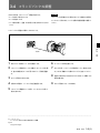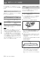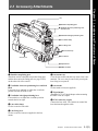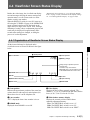
1
HD COLOR VIDEO CAMERA HDC-F950 電気製品は、安全のための注意事項を守らないと、火災 や人身事故になることがあります。 このオペレーションマニュアルには、 事故を防ぐための重要な注意事項と製 品の取り扱いかたを示してあります。 このオペレーションマニュアルをよく お読みのうえ、製品を安全にお使いください。お読みになったあとは、いつ でも見られるところに必ず保管してください。 OPERATION MANUAL 1st Edition (Revised 1) [Japanese/English] 安全のために ソニー製品は安全に十分に配慮して設計されています。しかし、電気製品は まちがった使い方をすると、 火災や感電などにより死亡や大けがなど人身事 故につながることがあり、危険です。 事故を防ぐために次のことを必ずお守りください。 安全のための注意事項を守る 警告表示の意味 このオペレーションマニュアル および製品では、次のような表 示をしています。表示の内容を よく理解してから本文をお読み ください。 3(J)∼6(J)ページの注意事項をよくお読みください。 定期点検を実施する 長期間安全に使用していただくために、 定期点検を実施することをおすすめ します。点検の内容や費用については、ソニーのサービス担当者または営業 担当者にご相談ください。 この表示の注意事項を守らない と、破裂、発火、発熱、液漏れ などにより死亡や大けがなどの 人身事故が生じます。 故障したら使用を中止する ソニーのサービス担当者または営業担当者にご連絡ください。 万一、異常が起きたら • 異常な音、 , におい、煙 が出たら • 落下させた ら 炎が出たら , 1 電源供給側の電源を切る。 2 光電気複合ケーブルや DC 電源コードを抜く。 3 ソニーのサービス担当者または営業担当者に修 理を依頼する。 この表示の注意事項を守らない と、火災や感電などにより死亡 や大けがなど人身事故につなが ることがあります。 この表示の注意事項を守らない と、感電やその他の事故により けがをしたり周辺の物品に損害 を与えたりすることがあります。 すぐに電源供給側の電源を切り、消火する。 注意を促す記号 行為を禁止する記号 行為を指示する記号 目次 警告 .............................................................................................................. 3(J) 注意 .............................................................................................................. 4(J) 電池についての安全上のご注意 ......................................................................... 6(J) 第1章 概要 1-1 1-2 特長 ....................................................................................................... 1-1(J) 第2章 各部の名称と働き 2-1 2-2 アクセサリー取り付け部 ...................................................................... 2-1(J) 第3章 準備 3-1 3-2 使用上のご注意 ..................................................................................... 3-1(J) システム構成 ........................................................................................ 1-3(J) コントロール部 ..................................................................................... 2-2(J) 接続と電源 ............................................................................................ 3-2(J) 3-2-1 接続 ......................................................................................................... 3-2(J) 3-2-2 電源の供給 ............................................................................................. 3-3(J) 3-3 3-4 3-5 3-6 3-7 第4章 記録のための調整と設定 レンズの取り付け ................................................................................. 3-4(J) フランジバックの調整 .......................................................................... 3-5(J) ビューファインダーの位置調整 ............................................................ 3-6(J) 三脚への取り付け ................................................................................. 3-8(J) ショルダーベルトの取り付け ............................................................... 3-9(J) 4-1 ブラックバランス/ホワイトバランスの調整 ......................................... 4-1(J) 4-1-1 ブラックバランスを調整する ................................................................... 4-1(J) 4-1-2 ホワイ トバランスを調整する .................................................................... 4-2(J) 4-2 電子シャッターの設定 .......................................................................... 4-4(J) 4-2-1 シャッターモードについて ....................................................................... 4-4(J) 4-2-2 シャッターモード/スピードを選択する ................................................... 4-4(J) 4-3 ビューファインダー画面上の設定メニュー表示 ................................... 4-6(J) 4-3-1 設定メニューの基本操作 ....................................................................... 4-7(J) 4-4 ビューファインダー画面上の状態表示 ................................................. 4-9(J) 4-4-1 ビューファインダー画面上の状態表示の構成 ...................................... 4-9(J) 4-5 USERメニューの使いかた ................................................................ 4-11(J) 4-5-1 USERメニューに任意のメニューページを設定するには ................... 4-11(J) 4-5-2 USER PAGEに任意の項目を設定するには ....................................... 4-12(J) 4-5-3 USERメニューを表示するには ............................................................ 4-14(J) 4-6 OPERATIONメニューによるセットアップ .................................... 4-15(J) 4-6-1 表示項目を選択する ............................................................................ 4-16(J) 4-6-2 ‘!’表示を点灯させる項目を選択する .............................................. 4-17(J) 4-6-3 マーカー表示を設定する...................................................................... 4-18(J) 4-6-4 ゲイン切り換え値を設定する................................................................ 4-19(J) 4-6-5 ビューファインダーを設定する.............................................................. 4-19(J) 4-6-6 オートアイリスを設定する ...................................................................... 4-20(J) 4-6-7 電源設定を表示する ............................................................................ 4-21(J) (続く) 目次 1(J) 日 本 語 目次 4-6-8 その他の設定 ....................................................................................... 4-21(J) 第4章 記録のための調整と設定 4-6-9 オペレーターファイルを操作する ......................................................... 4-22(J) 4-6-10 レンズファイルを表示する .................................................................. 4-22(J) (続き) 4-7 PAINTメニュー ................................................................................. 4-23(J) 撮影操作 ................................................................................................ 5-1(J) 第5章 撮影 5-1 付録 仕様 ................................................................................................................ A-1(J) 撮影前の点検 .................................................................................................. A-3(J) 用語解説 ......................................................................................................... A-4(J) 2(J) 目次 下記の注意を守らないと、 火災や感電により死亡や大けがにつながることがあります。 光電気複合ケーブルや DC 電源コードを傷つけない 光電気複合ケーブルやDC電源コードを傷つけると、火災や感電の原因とな ります。 ・ ケーブルを加工したり、傷つけたりしない。 ・ 重いものをのせたり、引っ張ったりしない。 ・ 熱器具に近づけたり、加熱したりしない。 ・ ケーブルを抜くときは、必ずプラグを持って抜く。 万一、ケーブルが傷んだら、ソニーのサービス担当者に交換をご依頼くだ さい。 3(J) 下記の注意を守らないと、 けがをしたり周辺の物品に損害を与えることがあります。 分解しない、改造しない 分解したり、改造したりすると、感電の原因となります。 内部に水や異物を入れない 水や異物が入ると火災や感電の原因となります。 万一、水や異物が入ったときは、すぐに電源供給側の電源を切り、光電気複 合ケーブルや接続コードを抜いて、 ソニーのサービス担当者または営業担当 者にご相談ください。 油煙、湯気、湿気、ほこりの多い場所では設置• 使用しない 上記のような場所で設置・使用すると、火災や感電の原因となります。 指定された CCU(カメラコントロールユニット)を使用する 指定以外の CCU を使用すると、火災や感電の原因となります。 側板をあけるときは、高温部分に触れない 機器を使用中または使用直後に側板を開けると、 電源部が高温になっている ため、やけどすることがあります。側板を開けて点検や調整を行うときは、 電源を切ってから少なくとも 10 分間放置してください。 回転式マルチコネクターは慎重に扱う 回転式マルチコネクターを乱暴に扱うと、 コネクター部が回転して指を挟む ことがあります。 ケーブルの接続および取り外しは無理な力をかけずに慎重 に行ってください。 使用中、放熱口をふさがない 内部温度が上昇して、筐体でやけどするおそれがあります。 4(J) 機器や部品の取り付けは正しく行う 別売りの機器や部品の取り付け方法を誤ると、 機器が落下して怪我をするこ とがあります。下記の機器や部品を取り付けるときは、マニュアルをよく読 んだうえ、確実に取り付けてください。 • レンズ •ショルダーベルト •三脚アタッチメント • バッテリー 5(J) 電池についての安全上のご注意 ここでは、本機での使用が可能なリチウムイオン電池およびバックアップ用マンガンリチウ ム電池についての注意事項を記載しています。 万一、異常が起きたら • 煙が出たら 1 機器の電源スイッチを切るか、バッテリーチャージャーの電源プラグを抜く。 2 ソニーのサービス担当者に連絡する。 • 電池の液が目に入ったら すぐきれいな水で洗い、ただちに医師の治療を受ける。 • 電池の液が皮膚や衣服に付いたら すぐにきれいな水で洗い流す。 • バッテリー収納部内で液が漏れたら よくふき取ってから、新しい電池を入れる。 下記の注意事項を守らないと、破裂・発火・発熱・液漏れにより、 死亡や大けがになることがあります。 • 充電には、ソニーの専用バッテリーチャージャーを使用する。 充電のしかたについては、バッテリーチャージャーの取扱説明書をよくお読みください。 • 火中に投入、加熱、はんだ付け、分解、改造をしない。 • 分解、改造をしない。 • 直射日光の当たるところ、炎天下の車内、ストーブのそばなど高温の場所で、使用・放 置・充電をしない。 • ハンマーでたたくなどの強い衝撃を与えたり、踏みつけたりしない。 • 接点部や 3 極と # 極をショートさせたり、金属製のものと一緒に携帯・保管をし ない。 下記の注意事項を守らないと、破裂・発熱・液漏れにより、死亡や 大けがなどの人身事故になることがあります。 • 所定の充電時間を超えても充電が完了しない場合は、充電をやめる。 • 電池使用中や充電、保管時に異臭がしたり、発熱・液漏れ・変色・変形などがあったと きは、すぐに使用や充電をやめ、火気から遠ざける。 下記の注意事項を守らないと、破裂・液漏れにより、けがをしたり 周辺の物品に損害を与えたりすることがあります。 • 投げつけない。 • 電池を使い切ったとき、長時間使わないときは、取り出しておいてください。 • 水や海水につけたり、濡らしたりしない。 6(J) 1-1 特長 第 1 HDC-F950は、HD-SDI 4:4:4 (RGB)出力を有するポータブルカ 2) フレーム蓄積モード対応(LFE 機能搭載) ラービデオカメラです。 HDカメラコントロールユニットHDCU-F950や VTRと接続すること CCD の蓄積読み出しにより、高感度化、ハイスピード効果、残像 により、主に映画制作用カメラとして機能します。 などの特殊効果を実現します。 高画質・高性能 多彩なディテールコントロール機能 新開発の 220 万画素、2/3 型 1080 Phase II FIT-CCDと、独自の スキントーンディテール機能 CCD出力信号プロセス回路および12ビットA/Dコンバーターの採 肌色を中心とした色相の色成分からディテールゲート信号を作り出 用により、高画質・高性能を実現しました。 すことにより、画面内の特定色相/彩度エリアのみに対してのディ また、HD-SDI 4:4:4 (Dual Link)対応により、さらに高画質での出 テール量のコントロール(強調 / 抑制)が可能です。 力が可能になりました。 ディテールブースト周波数コントロール ブースト周波数を20MHz∼30MHzの範囲で調整し、被写体に応 じてディテールの太さを適切な量に設定することで、より微妙な映 ワンピース筺体 像表現が得られます。 カメラアダプターを一体化し、放熱の効率化および徹底した低消 費電力化により信頼性の向上を図っています。 H/Vレシオコントロール また、 フィルターディスクはND、CCとも5枚を標準装備しています。 H ディテールとV ディテールの加わる比率が調整できます。 ホワイト/ブラックリミッター マルチフォーマット対応 ホワイ ト側/ブラック側のディテールを各々独立して抑制(リミット)で 24PsF、25PsF、30PsFに加え、60I、50Iにも対応可能です。 きます。 メニューによる簡単な設定操作 メモリースティック1) 本体にメモリースティックドライブを装備し、 メモリースティックによる セットアップデータの保存やカメラのソフトウェアのバージョンアップ などが可能です。 シャッタースピード、ECS3)、スーパーEVS モード4)、ビューファイン ダー画面の表示項目、映像ゲイン、セーフティゾーンマーカー5)/セ ンターマーカー6)、スクリーンサイズマーカーなどに関する選択や設 定を、ビューファインダー画面または外部モニター画面に表示され る設定メニューを見ながら、簡単かつ迅速に行えます。 ガンマテーブル/ユーザーガンマの選択 複数のガンマテーブルが用意されているため、マルチフォーマット に加え、自由度の高い画作りが可能です。 さらにガンマエディターを使用することによって、自由にガンマカー ブを作成することも可能です。 .............................................................................................................................................................................................................................................................. 1) “Memory Stick"および は、ソニ−株式会社の商 標です。 2) LFE(Long Frame Exposure) 蓄積数に応じた間欠出力となります。 3) ECS(Extended Clear Scan) 5) セーフティゾーンマーカー ビューファインダー画面上で、画面面積の80%または 90%、92.5%、95% の領域を示すボックス型のマーカー。 6) センターマーカー ビューファインダー画面の中心を示す十字マーカー。 ◆「4-2 電子シャッターの設定」を参照してください。 4) スーパーEVSモード 60I、50Iフォーマットのときのみ有効です。 ◆「4-2 電子シャッターの設定」を参照してください。 第 1章 概要 1-1(J) 章 概 要 第 1 章 概 要 1-1 特長 充実したビューファインダー内の表示 各種入出力コネクターを装備 ビューファインダー画面には、操作メッセージ、ゼブラパターン 1)、 • 光コネクター セーフティゾーンマーカー、センターマーカーなどに加え、本機の設 • HD SDI出力コネクター(4:4:4 Dual Linkカメラ出力 + 4:2:2 RET 定を文字や記号で表示することができます。 さらに、画面の上下に 第 1 章 概 要 出力) は、 タリーランプ、バッテリー残量警告ランプ、設定が標準状態では • DC 電源入出力コネクター ないことを示すランプなどが配置されています。したがって、本機 • プロンプター信号出力/外部同期信号入力/リターン信号入力コ の状態を容易に確認することができます。 ネクター(スイッチ切替) • EXT I/Oコネクター • RCP 接続コネクター 光デジタル伝送 • レンズ接続コネクター 光電気複合ケーブルを用い、カメラ-カメラコントロールユニット間 • ビューファインダー接続コネクター で 3 ギガビット デジタル光伝送を行います。 • インカムコネクター(2) • アナログオーディオ入力コネクター • イヤホンジャック 高解像度3型液晶マルチフォーマットカラー ビューファインダー HDC-F950の開発に伴い、新たにマルチフォーマット対応の3型液 •トラッカーコネクター • テスト出力コネクター • リターンコントロールコネクター 晶カラービューファインダーHDVF-C30Wを用意しました。 レーザービームについてのご注意 感電防止機能 接続が不完全なとき、HDCU (カメラコントロールユニット) からの高 電圧供給が停止します。 レーザービームはCCDに損傷を与えることがありま す。レーザービームを使用した撮影環境では、CCD 表面にレーザービームが照射されないように充分注 意してください。 .............................................................................................................................................................................................................................................................. 1) ゼブラパターン ビューファインダー画面上に現れる映像レベルが約70%および100%以 上の部分を示すしま模様。被写体の映像レベルの確認に使用します。 1-2(J) 第 1章 概要 1-2 システム構成 本機の関連機器およびアクセサリーを下図に示します。 HDエレクトロニック ビューファインダー HDVF-C750W HDエレクトロニック リターンビデオ セレクターCAC-6 第 1 章 概 要 ビューファインダー HDVF-20A HDエレクトロニック ビューファインダー バッテリーパック HDVF-C30W ビューファインダー 回転機構BKW-401 BP-L60/L80 バッテリーアダプター BKP-L551 HDカメラ コントロールユニット HDCU-F950 光ファイバーケーブル FC2-PD50/PD250 ズームレンズ HDカラービデオカメラ HDC-F950 リモート コントロール ユニット CCA-5ケーブル RM-B750 リモート コントロール ユニット HD CCDブロックアダプターHKC-T950 RM-B150 三脚アタッチメント VCT-14 第 1章 概要 1-3(J) 2-1 アクセサリー取り付け部 取っ手 1 ショルダーベルト取り付け金具 2 ビューファインダー前後位置固定レバーと ロックつまみ 第 2 章 各 部 の 名 称 と 働 き 3 ビューファインダー左右位置固定リング 4 レンズ用ケーブルクランプ 5 レンズ固定レバー 6 レンズマウントキャップ 7 レンズマウント ショルダーパッド 8 三脚マウント 9 LENS端子 1 ショルダーベルト取り付け金具 6 レンズマウントキャップ ショルダーベルトの一端をこの取り付け金具に取り付け、 もう一端を レンズを取り付けていないときは、このキャップをはめ込んでおい 右側面のショルダーベルト取り付け金具(2-8(J)ページ参照)に取 てください。レンズ固定レバーを押し上げると、取り外せます。 り付けます。 2 ビューファインダー前後位置固定レバーとロックつまみ ビューファインダーの位置を前後方向に調整するとき、このレバー とつまみをゆるめます。 3 ビューファインダー左右位置固定リング ビューファインダーの位置を左右方向に調整するとき、 このリングを ゆるめます。 4 レンズ用ケーブルクランプ 7 レンズマウント レンズ(別売り)を取り付けます。 8 三脚マウント 本機を三脚に固定するとき、三脚アタッチメントVCT-14を取り付け ます。 9 LENS(レンズ)端子(12ピン) レンズのケーブルを接続します。この端子を介して、本機からレン ズの機能をコントロールすることができます。 レンズのケーブルを固定します。 5 レンズ固定レバー レンズ(別売り)をレンズマウントに固定します。 第2章 各部の名称と働き 第 2 章 各 部 の 名 称 と 働 き 2-1(J) 2-2 2-2 コントロール部 コントロール部 前部(右) 1 INCOMボタン 2 RET 1ボタン 3 Y/RGBスイッチ 4 R/G/Bスイッチ 第 2 章 各 部 の 名 称 と 働 き 5 ASSIGNABLEスイッチ 6 FILTERつまみ 8 CAMERA/VTRスイッチ 9 GAINスイッチ 0 OUTPUT/AUTO KNEE スイッチ qa WHITE BALスイッチ 7 AUTO W/B BALスイッチ qs DISPLAYスイッチ qd CANCEL/STATUSスイッチ qf MENU SELつまみ/ ENTERボタン 1 INCOM(インターカム1)ボタン 5 ASSIGNABLE(アサイナブル)スイッチ 押している間、インターカム1 のマイクが ONになります。 OPERATIONメニューにより、機能を割り付けることができます。 2 RET 1(リターンビデオ1)ボタン ◆ 機能の割り付けかたについては、「4-6-8 その他の設定」(4-21(J) ページ)をご覧ください。 押している間、カメラコントロールユニットからのリターンビデオ1信 号をビューファインダー画面でモニターできます。側面のRET 1ボ タンと同じ機能です。 6 FILTER(内蔵フィルター切り換え)つまみ 被写体を照らしている光源に合わせて、適切なフィルターを選択し 3 Y/RGB(Y/RGB信号)スイッチ VFおよびTEST OUT端子から出力するビデオ信号を選択します。 Y:Y 信号を出力。(電源投入時の初期設定) RGB:R/G/Bスイッチで選択されたコンポーネントビデオ信号を 出力。 4 R/G/B(赤/緑/青)スイッチ Y/RGBスイッチが RGBに設定されているとき、VFおよび TEST OUT 端子から出力するコンポーネント信号を選択します。 2-2(J) 第2章 各部の名称と働き ます。 NDフィルター CC(色温度変換)フィルター 1 素通し A クロスフィルター 2 1/4 ND B 3200K 3 1/8 ND C 4300K 4 1/16 ND D 6300K 5 1/64 ND E 8400K 7 AUTO W/B BAL(ホワイトバランス/ブラックバランス 自動調整)スイッチ 1) qa WHITE BAL(ホワイトバランスメモリー切り換え)ス イッチ ホワイトバランスとブラックバランスを自動調整します。 WHT:ホワイトバランスを自動調整する。 BLK:ブラックバランスを自動調整する。 1) ホワイ トバランスの調整方式、および調整値を記憶するためのメモ リーを選択します。 PRST(プリセット):色温度 3200Kに対応するホワイトバランスの プリセット値に調整される。 8 CAMERA/VTRスイッチ 1) Aまたは B:メモリーAまたはBを選択する。AUTO W/B BALス 本機と接続したVTRへのコントロール信号を切り換えます。設定に イッチをWHT側に押すと、そのときのFILTERつまみの設定 より、VTRによる記録開始の機能が次のように変わります。 に応じてホワイトバランスが自動調整される。調整値は選択さ CAMERA VTR 機能 れたメモリーに記憶される。各メモリーに、4 個ずつ合計 8 個 OFF SAVE カメラの電源 OFF。 の調整値を記憶できる。 ON SAVE カメラの電源 ON。VTR STARTボタンを押すと、 数秒後に記録が始まる。 ON STBY カメラの電源 ON。VTR STARTボタンを押すと、 すぐに記録が始まる。 9 GAIN(ゲイン)スイッチ 1) 撮影時の照明の状態により、映像アンプのゲイン(利得)を切り換え ます。L、M、H の設定に対応するゲイン値はあらかじめ設定メ ニューで指定します。出荷時の設定は、L=0dB、M=6dB、H=12dB です。 OPERATIONメニューのVF DISPLAY ページのMESSAGE 設定 が ON の場合、このスイッチの設定を切り換えると、新しい設定が ビューファインダー画面の設定切り換え/調整経過メッセージ表示 部に約 3 秒間表示されます。 (例:「WHITE:Ach」 、 「WHITE:PRESET」 ) qs DISPLAY(ディスプレイ)スイッチ ビューファインダー画面内の表示(セーフティゾーンマーカー、セン ターマーカーおよび文字表示)およびメニュー画面のON/OFFを 行います。 ◆ ゲイン値の設定について詳しくは、 「4-6-4 ゲイン切り換え値を設定 する」(4-19(J)ページ)をご覧ください。 なお、OPERATIONメニューのVF DISPLAYページのMESSAGE 設定が ON の場合、このスイッチの設定を切り換えると、新しい設 定がビューファインダー画面の設定切り換え/ 調整経過メッセージ ON:ビューファインダー画面にオペレーション時の状態を示す文 字が現れる。 OFF:ビューファインダー画面の文字表示がすべて消える。 MENU:ビューファインダー画面に設定メニューが表示される。 ◆ 設定メニューと設定のしかたについては、 「4-6 OPERATIONメ ニューによるセットアップ」(4-15(J)ページ)をご覧ください。 表示部に約 3 秒間表示されます。 (例:「GAIN:12dB」) qd CANCEL/STATUS(取り消し/ステータス)スイッチ ビューファインダーにメニューが表示されているとき、 メニュー設定 0 OUTPUT/AUTO KNEE(出力信号選択/オートニー)ス イッチ 1) の内容を取り消したり、メニューの前画面に戻る働きをします。メ ニューが表示されていないときは、 ‘!’INDの項目を表示します。 本機からVTR、ビューファインダー、ビデオモニターへの出力信号 (カラーバー信号、またはカメラが撮影している映像)を選びます。 撮影している映像を出力信号として選択しているときは、オート ◆‘!’IND の項目については、 「4-6-2‘!’表示を点灯させる項目を選択 する」(4-17(J)ページ)をご覧ください。 ニー機能を使うことができます。 スイッチ設定と出力信号/オートニー機能の選択の関係は次のとお qf MENU SEL(メニュー選択)つまみ/ENTER(確定)ボ りです。 タン(ロータリーエンコーダー) OUTPUT AUTO KNEE 機能 BARS OFF カラーバー信号が出力される。 CAM OFF カメラで撮影している映像が出力される。 オートニー回路は機能しない。 CAM ON カメラで撮影している映像が出力される。 オートニー回路が機能する。 ビューファインダー画面に表示されたメニュー項目を選択(回転)/ 確定(押す)します。 .............................................................................................................................................................................................................................................................. 1) カメラコントロールユニット接続時は機能しません。 第2章 各部の名称と働き 2-3(J) 第 2 章 各 部 の 名 称 と 働 き 2-2 コントロール部 前部(左) 5 VF端子 第 2 章 各 部 の 名 称 と 働 き 1 TEST OUT端子 6 SHUTTERスイッチ 現在は使用しません 2 MIC 1 IN端子 3 RET 1ボタン 7 INCOM/EAR LEVELつまみ 8 VTR STARTボタン 4 MIC INスイッチ 1 TEST OUT(テスト出力)端子(BNC型) 4 MIC IN(マイク入力切り換え)スイッチ 必要に応じてモニターに接続します。 MIC1 IN端子に接続したマイクと後面のAUDIO IN CH-1端子に Y/RGBスイッチとR/G/Bスイッチで選択した信号を出力します。 接続したマイクのどちらを使用するかを選択します。 +48V/FRONT: MIC 1 IN端子に接続したマイクを使用し、マ 2 MIC 1 IN(マイク1入力)端子(XLR型、3ピン、メス) マイクを接続します。 MIC INスイッチによって、後面の AUDIO IN CH-1 端子と切り換 イクに+48 V の電源を供給します。 OFF/FRONT: MIC 1 IN 端子に接続したマイクを、電源を供 給しないで使用します。 REAR: 後面の AUDIO IN CH-1 端子に接続したマイクを使用 えます。 します。マイクへ電源を供給するかどうかは、後面のAUDIO 3 RET 1(リターンビデオ1)ボタン IN CH-1 端子用のマイク電源スイッチで設定できます。 押している間、カメラコントロールユニットからのリターンビデオ1信 号をビューファインダー画面でモニターできます。取っ手上部およ 5 VF(ビューファインダー)端子(20ピン) び右側面のRET 1ボタンと同じ機能です。 ビューファインダーのケーブルを接続します。 2-4(J) 第2章 各部の名称と働き 6 SHUTTER(シャッター)スイッチ 1) OFF: 電子シャッターは働かない。 ON: 電子シャッターを使用する。 SEL: スイッチをこの位置にすると、シャッタースピードおよび シャッターモードの設定が切り換わる。 ◆詳しくは「4-2 電子シャッターの設定」 (4-4(J)ページ)をご覧ください。 7 INCOM/EAR LEVEL(インターカム/イヤホン音量)つ まみ インカムおよびイヤホンの音声レベルを調整します。 第 2 章 各 部 の 名 称 と 働 き インカムレベルの調整は後面(右)パネルの INCOM LEVELス イッチが F 側に設定されているときに有効です。 8 VTR START(記録開始/停止ボタン)ボタン VTRを接続しているときは、押すと記録が始まり、もう一度押すと 止まります。レンズに付いているVTRボタンと同じ働きをします。 カメラコントロールユニット接続時は、OPERATIONメニューにより、 RET2/INCOM1 MIC/INCOM2 MIC のスイッチ機能に変更する こともできます。 ◆詳しくは、 「4-6-8 その他の設定」(4-21(J)ページ)をご覧ください。 .............................................................................................................................................................................................................................................................. 1) カメラコントロールユニット接続時は機能しません。 第2章 各部の名称と働き 2-5(J) 2-2 コントロール部 後面(左) 1 タリーランプとタリースイッチ 第 2 章 各 部 の 名 称 と 働 き 2 CCU端子 3 INCOM1、2端子 4 EARPHONEジャック 8 RET CONT端子 5 TRACKER端子 9 EXT I/O端子 0 REMOTE端子 6 GENLOCK IN/RET IN/ PROMPTER OUT端子と qa DC OUT端子 切り換えスイッチ qs DC IN端子 qd HD SERIAL RET OUT端子 qf HD SERIAL LINK A/LINK B OUT端子 7 AUDIO IN 1、2端子/スイッチ 1 タリーランプとタリースイッチ ON:外部からのタリーボタンやCALLボタンなどによる呼び出し 時にタリーランプが点灯する。 OFF:タリーランプを点灯禁止にする。 5 TRACKER(トラッカー)端子(20ピン) この端子を介して、 カメラマンとトラッカーとの通話およびインターカ ム1、2 の送受信ができます。また、アップタリー信号とプログラム オーディオ信号を出力します。 トランクラインの入出力信号もアサイ ンされています。 2 CCU(カメラコントロールユニット)端子(光マルチコ 6 GENLOCK IN/RET IN/PROMPTER OUT(外部同期 ネクター) 光電気複合ケーブルでカメラコントロールユニットと接続します。 信号入力/リターン信号入力/プロンプター信号出力)端子 (BNC型)と切り換えスイッチ 4 INCOM1、2(インターカム1、2)端子(XLR型5ピン) 切り換えスイッチで端子の機能を選択します。 インターカムの音声信号を入出力します。 (スタンドアローン GENLOCK IN:外部同期用信号を入力する 4 EARPHONE(イヤホン)ジャック(ミニジャック) RET IN:リターン信号を入力する(スタンドアローン使用時のみ 使用時のみ有効) 。 イヤホン、ヘッドホンなどを接続し、VTRの再生音声信号を出力し 有効) 。 (カメラコン PROMPTER OUT:プロンプター信号を出力する ます。 トロールユニット接続時のみ有効) 。 2-6(J) 第2章 各部の名称と働き 7 AUDIO IN(オーディオ入力)1、2端子(XLR型3ピ qs DC IN(DC電源入力)端子(XLR型4ピン) ン)/スイッチ ACアダプターAC-550、バッテリーなどを接続し、本機に電源を供 オーディオ信号を入力します。チャンネル1、2それぞれに対して入 給します。 力選択スイッチ、マイク電源スイッチが用意されています。 qd HD SERIAL RET OUT(HDシリアルリターン出力) 端子(BNC型) 入力選択スイッチ マイク電源スイッチ HD SDI のシリアルデータを出力します。カメラコントロールユニッ トからのリターン信号を出力します。 qf HD SERIAL LINK A/LINK B OUT(HDシリアルリン LINE MIC OFF+48V LINE MIC OFF+48V クA/リンクB出力)端子(BNC型) AUDIO IN カメラの本線信号をHD-SDI 4:4:4 (Dual Link)として出力します。 CH-1 CH-1 入力選択スイッチ:入力する外部音声信号を選択します。 LINE:ライン入力を接続するとき。 MIC:マイクを接続するとき(マイクのゲイン設定は、メ ニューで行います) 。 マイク電源スイッチ:マイクを接続したとき、マイクに電源を供 給するかどうかを設定します。 +48V: +48 V の電源をマイクに供給する。 OFF: 電源をマイクに供給しない。 : +12 Vの電源をマイクに供給する。 ● ご注意 +12 V 電源を供給するためにはセットの改造が必要です。 ◆ 詳しくは、インストレーション&メンテナンスマニュアルを参照してくださ い。また、実際の作業はサービス担当者にご依頼ください。 8 RET CONT(リターンコントロール)端子(6 ピン) リターンビデオセレクターCAC-6を接続します。 9 EXT I/O(外部入出力)端子(20ピン) 外部に Y/Pb/Pr 信号などを送り出すための端子です。 0 REMOTE(リモート)端子(8ピン) リモートコントロールユニットRM-B150/B750、リモートコントロール パネル RCP-700シリーズ、またはマスターセットアップユニット MSU-700A/750を接続します。 qa DC OUT(DC電源出力)端子(4ピン) 別売りのワイヤレスレシーバーなどに電源を供給します。 第2章 各部の名称と働き 2-7(J) 第 2 章 各 部 の 名 称 と 働 き 2-2 コントロール部 後面(右) ショルダーベルト取り付け金具(2-1(J)ページ参照) 第 2 章 各 部 の 名 称 と 働 き 3 RET1ボタン 4 RETボタン/スイッチ 5 INCOM1、2つまみ/スイッチ 6 CALLボタン 1 メモリースティック部 2 POWERスイッチ 1 メモリースティック部 3 RET 1(リターンビデオ1)ボタン 蓋の中に、メモリースティックを挿入するスロットと、取り出すときに 押している間、カメラコントロールユニットからのリターンビデオ1信 押すイジェクトボタンがあります。 号をビューファインダー画面でモニターできます。 スロットに挿入したメモリースティックにデータを書き込んだり、メモ リースティックからデータを読み出しているときはイジェクトボタンが 4 RET(リターンビデオ)ボタン/スイッチ 赤く点灯します。 リターンビデオ1と並行して別の系統のシステムを使用している場 合、スイッチで選択した信号(リターンビデオ2、3、4)を、ボタンを押 ご注意 イジェクトボタンが点灯しているときはメモリースティックを抜き差し している間ビューファインダー画面でモニターできます。 しないでください。 ご注意 ◆ メモリースティックの操作については、システムマニュアルおよび 「4-6-9 オペレーターファイルを操作する」 (4-22(J)ページ)を参照して ください。 2 POWER(電源)スイッチ CCU:カメラコントロールユニットからの給電で電源が入ります。 EXT:DC INまたは VTR 端子からの給電で電源が入ります。 RET 1ボタンとRETボタンを両方とも押した場合は、RET 1ボタン が優先されます。 5 INCOM1、2(インターカム1、2)つまみ/スイッチ インターカムライン1、2それぞれに対し、PGM 調整つまみ /スイッ チ、ライン選択スイッチ、LEVEL/TALKスイッチ、および INCOM 調整つまみが用意されています。 2-8(J) 第2章 各部の名称と働き INCOM1側 PGM PGM調 整 つ ま み / 1 スイッチ 2 PGM INCOM2側 (構成は1側と同じ) PGM PGM 1 2 PROD ライン選択スイッチ LEVEL/TALK スイッチ PROD INCOM INCOM ENG ENG LEVEL TALK LEVEL TALK R ON 1 F OFF INCOM R ON F OFF 2 INCOM INCOM調整つまみ 第 2 章 各 部 の 名 称 と 働 き PGM(プログラム)調整つまみ / スイッチ:プログラム音声の受 信レベルを調整します。 それぞれ対応するスイッチで、 プログ ラム1 か 2を選択できます。 ライン選択スイッチ:インターカムラインを選択します。 PROD:プロデューサーラインを使用するとき。 ENG:エンジニアラインを使用するとき。 LEVEL/TALK(レベル /トーク)スイッチ: R/ON:インターカム用ヘッドセットのマイクをONにします。 インターカム音声の受信レベルは INCOM 調整つまみで 調整します。 R/OFF:インターカム用ヘッドセットのマイクをOFFにします。 インターカム音声の受信レベルは INCOM 調整つまみで 調整します。 F/OFF:インターカム用ヘッドセットのマイクをOFFにします。 インターカム 音 声 の 受 信レ ベ ル は 、カメラ前 面 の INCOM/EAR LEVEL つまみで調整できます。 INCOM(インターカム)調整つまみ:インターカム音声の受信レ ベルを調整します。 6 CALL(コール)ボタン 押すと、RCP-700シリーズ(リモートコントロールパネル)や MSU700A /750(マスターセットアップユニット)レッドタリーランプが点灯 します。RCP や MSU オペレーターを呼び出すときに使います。 第2章 各部の名称と働き 2-9(J) 3-1 使用上のご注意 第 3 章 準 備 強い衝撃を与えない 内部構造や外観の変形などの損傷を受けることがあります。 使い終わったら 電源スイッチを切ってください。 使用、保管場所 水平な場所、空調のある場所に保管してください。 次のような場所での使用および保管は避けてください。 • 極端に暑い所や寒い所 • 湿気の多い所 • 激しく振動する所 • 強い磁気を発生する所 • 直射日光が長時間あたる所や暖房器具の近く 第 3 章 準 備 第 3章 準備 3-1(J) 3-2 接続と電源 3-2-1 接続 本機には、VTR、カメラコントロールユニット、またはリモートコント ロールパネルを接続することができます。 接続ケーブル HDC-F950 CCA-5 VTRの接続 • リモートコントロール ユニットRM-B750/B150 • リモートコントロール パネルRCP-700シリーズ 本機に取り付けたカメラアダプターに、下図のようにVTRを接続す ることができます。 HDC-F950 リモートコントロールパネル/ユニットを接続する 第 3 章 準 備 リモートコントロールで使用可能な機能 HD SERIAL LINK A / LINK B OUT BNCケーブル カメラコントロールユニットを接続してリモートコントロールパネルや リモートコントロールユニットから操作する場合、 リモートコントロール でも本機のメニュー操作と同様に、以下の機能が働きます。 4:4:4対応 HD VTR • オートーセットアップ(レベル調整、オートブラック/ホワイ トレベル調 整) • シーンファイル、セットアップファイルデータのクリア • ペインティングデータのクリア • テスト信号の出力 カメラアダプターとカメラコントロールユニッ ト/リモートコントロールパネルの接続 リモートコントロールパネルやリモートコントロールユニットからオート HDカメラコントロールユニットHDCU-F950 や RCP-700シリーズの セットアップを実行する場合は、カラーバーまたはテスト信号を出力 リモートコントロールパネル、または RM-B750などのリモートコント している状態でもセットアップが可能です。セットアップ終了後は、 ロールユニットを接続することができます。 再びカラーバーまたはテスト信号がビューファインダー画面に表示さ カラーバーまたはテスト信号の出力について れます。 ◆詳しくはシステムマニュアルをご覧ください。 光ファイバーケーブル HDC-F950 FC2-PD50/PD250 マイク出力 カメラコントロール ユニット 映像出力 HDCU-F950 電源入力 カメラコントロールユニットを接続する 3-2(J) 第 3章 準備 バッテリーパックを使う 3-2-2 電源の供給 本機は次のいずれかの電源を使用します。 • 接続された機器の電源 バッテリーパックを使って電源を供給する場合は、POWERスイッチ をEXTにして、本機にバッテリーアダプターまたはバッテリーケース を取り付けます。 • ACアダプターを介して接続された電源 • 装着されたバッテリー電源 ご注意 バッテリーケースDC-L1/L90は直接本機に取り付けることはできま せん。 カメラコントロール ユニット バッテリーパックBP-L60/L80を使うには HDCU-F950 別売りのバッテリーアダプターBKP-L551を使います。 ◆ 詳しくは、インストレーション&メンテナンスマニュアルをご覧ください。 第 3 章 準 備 光マルチ コネクター HDカラービデオカメラ HDC-F950 DC IN 端子 • ACアダプター AC-550 • バッテリーアダプ ターBKP-L551 +バッテリーパッ クBP-L60/L80 POWERスイッチをCCUに設定すると、カメラコントロールユニッ トが接続されているときに電源が入ります。また、EXTに設定する と、DC IN 端子から給電されているときに電源が入ります。 第 3章 準備 3-3(J) 3-3 レンズの取り付け ◆ レンズの取り扱いについては、 レンズに付属の取扱説明書をご覧くださ い。 本機に取り付ける手順は、次のとおりです。 第 3 章 準 備 5 2 1 レンズ固定レバーを押し上げて、 レンズマウントからレンズマウ 4 1,3 4 レンズケーブルをLENS 端子に接続する。 5 レンズケーブルをケーブルクランプに押し込む。 ントキャップを外す。 2 レンズマウント上部中央の凹部にレンズの位置決めピンを合わ せ、レンズをマウントに差し込む。 3 レンズを支えながら、レンズ固定レバーを押し下げてレンズを 固定する。 3-4(J) 第 3章 準備 3-4 フランジバックの調整 次のような場合、フランジバック1)の調整が必要です。 ご注意 • レンズを初めて取り付けたとき フランジバックの調整のために操作するレンズの各部分の位置は、 • レンズを交換したとき レンズによって異なります。 レンズに付属の取扱説明書で確認して • ズーム操作の際に、望遠・広角の両方で焦点がきちんと合わな ください。 いとき フランジバックの調整の手順は、次のとおりです。 第 3 章 準 備 約3m 1 絞りのモードを手動にして、絞りを開放にする。 6 ズームリングを広角位置にする。 2 フランジバック調整用チャートを本機から3mぐらいの所に置 7 Ffリングを回し、 フランジバック調整用チャートに焦点を合わせ る。 このとき、距離リングを動かさないように注意してください。 き、適正な映像出力レベルが得られるように、照明を調整す る。 8 3 Ff リング固定ネジをゆるめる。 4 手動または電動で、ズームリングを望遠位置にする。 5 フランジバック調整用チャートを写し、 フォーカスリングを回して 2) 遠望と広角の両方で焦点が合うようになるまで、手順4∼7の 操作を繰り返す。 9 Ffリング固定ネジをしっかり締める。 焦点を合わせる。 ............................................................................................................................................................................................................................................................. 1) フランジバック レンズマウントの取り付け面から結像面までの距離 2) Ff Flange focal length 第 3章 準備 3-5(J) 3-5 ビューファインダーの位置調整 ビューファインダーの位置を左右方向および前後方向に調整して、 本機をキャリングケースに収納するときは ビューファインダー内を見やすくすることができます。 ビューファインダーをマイク側いっぱいに寄せ、ビューファインダー 左右位置固定リングを締めた状態で収納します。 左右方向の調整 前後方向の調整 3 1 1 1 2 3 3 第 3 章 準 備 2 1 ビューファインダー左右位置固定リングをゆるめる。 2 ビューファインダーを左右にスライドさせ、内部が見やすい位置 1 る。 に調整する。 3 ビューファインダー左右位置固定リングを締める。 ビューファインダー前後位置固定レバーとロックつまみをゆるめ 2 ビューファインダーを前後にスライドさせ、内部が見やすい位置 に調整する。 3 ビューファインダー前後位置固定リングとロックつまみを締め る。 3-6(J) 第 3章 準備 ビューファインダーが脚に当たらないようにする には 本機を持ち運ぶときに、 ビューファインダーが脚に当たらないように するには、ビューファインダー回転機構BKW-401(別売り)を取り付 けて、ビューファインダーを上部に回転させておきます。 第 3 章 準 備 m ご注意 ビューファインダーを上部に回転させる前に、ビューファインダーを 少し前に引き出した位置で固定してください。 ビューファインダーの 前後方向の位置が最後部になっていると、 ビューファインダー回転 機構のアームが本機の取っ手に当たります。 第 3章 準備 3-7(J) 3-6 三脚への取り付け 別売りの三脚アタッチメントVCT-14を使って本機を三脚に取り付け るには、次のようにします。 1 三脚アタッチメントを三脚に取り付ける。 三脚アタッチメントの底部にある穴のうち、本機と三脚アタッチ メントの重心を考慮して、適切な位置の穴を選びます。選んだ 穴の径が、雲台のカメラ取り付けネジの径と合うことを確認し 三脚 アタッチメント ます。 雲台 三脚 第 3 章 準 備 2 本機を三脚アタッチメントに取り付ける。 アタッチメントの溝に沿って、カチッと音がするまで、本機を前 方にすべらせます。 三脚 アタッチメント 三脚アタッチメントから取り外すには 赤いボタンを押しながら、レバーを矢印の方向へ動かします。 ピンが元の位置に戻らない場合 本機を取り外した後、三脚アタッチメントのピンが元の位置(ピン収 納部)に戻らない場合は、もう一度、赤いボタンを押しながら、レ バーを矢印の方向へ動かして、ピンをもとの位置に戻します。ピン が出たままでは、本機の取り付けができません。 ピン収納部 レバー 赤いボタン ピン 3-8(J) 第 3章 準備 3-7 ショルダーベルトの取り付け 本機を肩から下げて使用する場合は、別売りのショルダーベルトを 取り付けるには ショルダーベルト取り付け金具に取り付けます。 クリップ ショルダーベルト 取り付け金具 ベルトを上に引っ張って きちんと固定する。 f 第 3 章 準 備 取り外すには ここを押しながら 矢印の方向に引く。 f 第 3章 準備 3-9(J) 4-1 ブラックバランス/ホワイトバランスの調整 本機を使用し、常に高画質の映像を得るためには、状況に応じた ブラックバランスとホワイトバランスの調整が必要です。 ブラックバランス調整の手順 1 図のようにスイッチを設定する。 ブラックバランスの調整 次のような場合に調整が必要です。 OUTPUT/AUTO KNEE:CAM • 本機を初めて使用するとき • 長時間使用しなかった後に使用するとき • 周囲の温度が大幅に変化した状況で使用するとき • 設定メニューでゲイン切り換え値を変更したとき 通常は、電源を再び入れた場合でも調整し直す必要はありませ 第 4 章 記 録 の た め の 調 整 と 設 定 ん。 ホワイトバランスの調整 DISPLAY:OFF GAIN:できるだけ小さい 照明条件が変わったときには、必ず調整し直してください。 ゲイン値を選択する。 ビューファインダー画面の表示について ブラックバランスとホワイトバランスの調整を始めると、 ビューファイ ンダー画面に、調整経過や結果をしらせるメッセージが表示され 2 AUTO W/B BALスイッチをBLK側に押して、指を放す。 第 4 章 記 録 の た め の 調 整 と 設 定 ます。 ご注意 本機で自動調整される調整値や各設定値は、本機のメモリーに 記憶され、電源を切っても保持されています。 AUTO W/B BALスイッチ 4-1-1 ブラックバランスを調整する スイッチは中央に戻り、調整が実行されます。 ブラックバランスの自動調整は、ブラックセット、ブラックバランスの 順に実行されます。 調整中、 ビューファインダー画面上に図のようなメッセージが また、 ブラックシェーディングを調整することもできます。 表示されます。 ブラックバランスは、設定メニューの操作によって手動調整するこ ともできます。 ◆ ブラックバランスの手動調整については、インストレーション&メンテナ ンスマニュアルをご覧ください。 ABB:OP 数秒で調整が終了し、 「ABB:OK」のメッセージが表示されま す。調整値は自動的にメモリーに記憶されます。 第4章 記録のための調整と設定 4-1(J) 4-1 ブラックバランス/ホワイトバランスの調整 ご注意 GAINおよび WHITE BALスイッチ の設 定を変 更 すると、 ビューファインダー画面の設定変更/調整経過メッセージ表 • ブラックバランス調整中、絞りは自動的に遮光状態になりま 示部に、設定した位置を知らせるメッセージが約3秒間表示さ す。 れます (OPERATIONメニューの VF DISPLAYページ で • ブラックバランス調整中、ゲイン切り換え回路が自動的に切り MESSAGE設定がONのとき)。 換わり、 また、 ビューファインダー画面上にフリッカーが数回現 れますが、故障ではありません。 2 照明条件に合わせて、FILTERつまみの設定を切り換える。 ブラックバランスの自動調整ができないとき ブラックバランスの調整が正常に終了しなかったときは、 ビュー NDフィルター 色温度変換フィルター ファインダー画面に約3秒間エラーメッセージ 「ABB:NG」 が表示さ 1 素通し A クロスフィルター れます。 2 1/4 ND B 3200K エラーメッセージが表示されたら、再度ブラックバランスの調整を 3 1/8 ND C 4300K 試みてください。 4 1/16 ND D 6300K 5 1/64 ND E 8400K 繰り返し調整を試みてもエラーメッセージが表示されるときは、内 部点検をする必要があります。 FILTERつまみの設定を変更すると、 ビューファインダー画面 の設定変更/調整経過メッセージ表示部に、設定した位置を ◆ 内部点検については、 インストレーション&メンテナンスマニュアルをご 覧ください。 第 4 章 記 録 の た め の 調 整 と 設 定 知らせるメッセージが約3秒間表示されます(OPERATIONメ ニューのVF DISPLAYページのMESSAGE設定がONのと き)。 ブラックバランスのメモリーについて メモリーに記憶された値は、本機の電源を切った状態でも保存さ 3 被写体の照明光源と同じ条件のところにホワイトパターンを 置き、ズームアップして画面に白を映す。 れます。 被写体の近くの白いもの(白布、白壁)で代用することもでき ます。 4-1-2 ホワイトバランスを調整する 最小限必要な白の面積は、図のとおりです。 以下の手順でホワイ トバランスを自動調整します。 1 画面センターを中心と する長方形。 各辺の長さは、画面の 高さ、または幅の70%。 図のようにスイッチを調整する。 FILTERつまみ OUTPUT/AUTO KNEE:CAM この長方形内に、画面 面 積 の 10%以 上 の 面 積の白が必要。 ご注意 WHITE BAL:AまたはB DISPLAY:OFF GAIN:できるだけ小さい ゲイン値に設定する。 長方形内に高輝度スポットを入れないようにしてください。 4 レンズの絞りを調整する。 手動調整レンズの場合:絞りを適正値に合わせる。 自動絞り調整機能付きレンズの場合 :レンズ側の絞り自動/ 手動切り換えスイッチを自動に設定する。 4-2(J) 第4章 記録のための調整と設定 5 AUTO W/B BALスイッチをWHT側に押して、指を離す。 ホワイトバランスの自動調整ができないとき ホワイトバランスの調整が正常に終了しなかったときは、ビュー ファインダー画面に約3秒間エラーメッセージ 「AWB:NG」 が表示さ れます。 エラーメッセージが表示されたら、再度ホワイトバランスの調整を 試みてください。 AUTO W/B BALスイッチ スイッチは中央に戻り、ホワイトバランスの自動調整が実行さ れます。 調整中、 ビューファインダー画面の左下に「AWB:OP」のメッ 繰り返し調整を試みてもエラーメッセージが表示されるときは、内 部点検をする必要があります。 ◆ 内部点検については、別売りのメンテナンスマニュアルをご覧くださ い。 ホワイトバランスを調整する時間がないときは セージが表示されます。 WHITE BALスイッチをPRSTにします。FILTERつまみの設定位 約1秒で、図のようなメッセージが表示され、調整が完了しま 置に従って、 ホワイトバランスが自動的にとれます。 す。調整値は、手順1で選択したメモリー(AまたはB)に自動 的に記憶されます。 ホワイトバランスのメモリーについて メモリーに記憶された値は、本機の電源を切っても保存されます。 ホワイトバランスのメモリーは、A、Bの2系統があり、AUTO W/B BALスイッチをWHT側に押すと、そのときのFILTERつまみの設 定に応じてホワイトバランスが自動調整されます。調整値は選択さ れたメモリーに記憶されます。各メモリーに、5個ずつ合計10個の AWB:OK 調 整 値 を 記 憶 できます 。A、B各 系 統 の メモリー の 数 は 、 MAINTENANCEメニューで、それぞれ1個に限定することもでき ご注意 自動絞り機能付きズームレンズを使用した場合、絞りがハンチン レンズに付いている絞りのゲインつま グ1)を起こすことがあります。 ます。 この場合、メモリーの内容はフィルターに連動しません。 ◆ MAINTENANCEメニューでの設定については、 インストレーション&メ ンテナンスマニュアルをご覧ください。 み(IG、IS、Sなどと表示されている)を調整してください。 ◆ 詳しくは、 レンズの取扱説明書をご覧ください。 ............................................................................................................................................................................................................................................................ 1) ハンチング オートアイリスの応答を繰り返し、映像が暗くなったり明るく なったりすること。 第4章 記録のための調整と設定 4-3(J) 第 4 章 記 録 の た め の 調 整 と 設 定 4-2 電子シャッターの設定 ここでは、本機の電子シャッターで使用できるシャッターモードに 4-2-2 シャッターモード/スピードを選 ついて説明し、 シャッターモードとシャッタースピードの設定手順を 択する 示します。 シャッターモードおよび標準モードでのシャッタースピードは SHUTTERスイッチを切り換えて設定します。 4-2-1 シャッターモードについて 本機の電子シャッターで使用できるシャッターモードと、選択でき るシャッタースピードは次のとおりです。 設定できるシャッターモードとシャッタースピード シャッター モード 標準 シャッタースピード1) 第 4 章 記 録 の た め の 調 整 と 設 定 1 「4-5-1 表示項目を選択する」(4-11(J)ページ)の手順を使用 して、OPERATIONメニューのVF DISPLAYページで 用途 SHUTTERをONに設定する。 1/32、1/48、1/96、 動きの早い被写体を鮮明に 1/125、1/250、1/500、 撮影したい場合 1/1000 (秒) 24.0 Hz∼2200 Hz の範 ECS (拡張クリア 囲で連続可変 スキャン) シャッターモードおよび標準モードでのシャッ タースピードを設定するには 2 SHUTTERスイッチを、ONの位置からSEL側に押す。 モニター画面を、水平方向 の縞模様が出ないように撮 影したい場合 1)表の数値は、24PsF、23.98PsF時のものです。他のフォーマットで は設定できる値が異なります。他のフォーマットで設定できる値 については、4-27(J)ページをご覧ください。 SHUTTERスイッチ ご注意 • どのモードで電子シャッターを使用しても、シャッタースピード ビューファインダー画面の設定変更/調整経過メッセージ表 が速くなるにつれ、絞りが開き、被写体深度も浅くなります。 示部に、 シャッターの現在の設定が約3秒間表示されます。 • 人工照明、特に蛍光灯や水銀灯などは、輝度が一定のように見 例:「Shutter:1/250」 えても、電源周波数に同期して、R、G、B各色の強さが変化して います(これをフリッカーと言います)。このような照明下で 3 手順2の表示が消える前に、 もう1度SHUTTERスイッチをSEL シャッターを使用すると、フリッカーがより目立つ場合がありま 側に押す。希望のモードまたはスピードが表示されるまで、 こ す。特に、電源周波数が60Hzの地域では、カラーフリッカーとな の操作を繰り返す。 1 ります。なお、50Hzの地域では、シャッタースピードを /100に設 すべてのモードとスピードが表示される場合は、次のような順 定すると、 フリッカーを低減することができます。 序で表示が切り換わります。 例: 24PsF/23.98PsF時 標準モード 1/32 1/48 1/96 1/125 1/250 1/500 1/1000 ECSモード 出荷時には、左の表にあるすべてのモードとスピードが表示 されるように設定されていますが、 あらかじめ必要なシャッ ターモードとスピードだけを設定しておくこともできます。 ◆ 詳しくは、 インストレーション&メンテナンスマニュアルをご覧くださ い。 4-4(J) 第4章 記録のための調整と設定 ECSモードを選択したときは 本機前面のMENU SELつまみ/ENTERボタンを回転させてス ピードを変更することができます。 1度選択したシャッタースピードは、本機の電源を切った状態でも 保持されます。 第 4 章 記 録 の た め の 調 整 と 設 定 第4章 記録のための調整と設定 4-5(J) 4-3 ビューファインダー画面上の設定メニュー表示 DISPLAYスイッチをMENUに設定すると、 ビューファインダー画面 TOPメニューには、次のようなサブメニューがあります。 上にOPERATIONメニューが表示されます。 OPERATIONメニューはページ単位で表示されます。 USERメニュー OPERATIONメニューは、各種設定値の選択や、 ビューファイン USERメニューは、ユーザーがメニューの中からよく使用する項目 ダー画面上に表示させる項目とその表示方法の選択に使用しま を選択して入れておきます。最大60ページまで追加可能です。項 す。 目、ページの追加、削除はUSER MENU CUSTOMIZEメニュー で行ないます。 TOPメニューについて メニュー項目の全体構成を示す画面としてTOPメニュー画面が あります。 TOPメニュー画面 < TOP MENU > cUSERS USER MENU CUSTOMIZE OPERATION PAINT MAINTENANCE FILE DIAGNOSIS 第 4 章 記 録 の た め の 調 整 と 設 定 USER MENU CUSTOMIZEメニュー USERメニューに必要なページや項目を追加、削除するときに使 用します。 ◆ 詳しくは「4-5 USERメニューの使いかた」 (4-11(J)ページ) をご覧くださ い。 OPERATIONメニュー 通常カメラマンが本機を運用するときに必要なVF内のマーカー や文字表示などの設定を変更する項目が含まれています。 通常、DISPLAYスイッチをMENUに切り換えると、 このメニューが 表示されます。 ご注意 内部SG基板のスイッチ設定により、TOPメニューの内容は異なり ます。 ◆ 詳しくは、 インストレーション&メンテナンスマニュアルをご覧ください。 ◆ このメニューで 行う調 整 やセットアップに つ い て 詳しくは、 「 4-6 OPERATIONメニューによるセットアップ」 (4-15(J)ページ) をご覧くだ さい。 PAINTメニュー 波形モニター等を使用してカメラの出力の波形を監視しながら、 TOPメニュー画面を表示させるには 細かな画像調整をするための設定項目が含まれています。通常、 STATUS/CANCELスイッチをSTATUS側に倒しながらDISPLAY 各項目の設定を行うにはビデオエンジニアのサポートが必要で スイッチをOFF からMENUに切り換えます。 す。 項目の設定は、外部のリモートコントロールパネルやマスターセット アップユニットなどでも行えますが、 このメニュー自体は、本機を 屋外で単体で使用する場合に有効です。MSU-700A/750の PAINTメニューとほぼ同等です。 ◆ このメニューで行う設定項目については、 「4-7 PAINTメニュー」 (4-23(J)ページ) をご覧ください。 DISPLAYスイッチ STATUS/CANCELスイッチ MENU SELつまみ/ENTERボタン MAINTENANCEメニュー 使用頻度の低い設定項目が含まれています。MSU-700A/750の MAINTENANCEメニューとほぼ同等です。 FILEメニュー リファレンスファイル、OHBファイル、 レンズファイル、オペレーター プリセットファイルの書き込みおよびクリアなどのファイル操作を行 います。 4-6(J) 第4章 記録のための調整と設定 3 DIAGNOSISメニュー MENU SELつまみ/ENTERボタンを押す。 自己診断情報を表示します。 選択したページの各項目の設定内容が表示され、現在の選 TOPメニューに戻るには 択項目に→マークが付きます。 次の2とおりの方法があります。 • メニュー画面の各ページの右上に表示されているTOPに→ マークを合わせ、MENU SELつまみ/ENTERボタンを押す。 EX :c ON ZOOM : OFF FOCUS : OFF ND : ON CC : ON IRIS : ON WHITE : OFF D5600K: ON GAIN : ON SHUTT : ON • STATUS/CANCELスイッチをCANCEL側に2度押す。 TOPメニュー画面に戻ります。 ◆ これらのメニューについて詳しくは、インストレーション&メンテナンスマ ニュアルおよびシステムマニュアルをご覧ください。 4-3-1 設定メニューの基本操作 1 <VF DISPLAY> 4 BATT : OFF RETURN: ON MESSAG: ALL MENU SELつまみ/ENTERボタンを回して、→マークを設 定したい項目に移動する。 5 MENU SELつまみ/ENTERボタンを押す。 →マークが?マークに変わり、点滅します。 6 MENU SELつまみ/ENTERボタンを回して、設定値を変更 する。 DISPLAYスイッチ STATUS/CANCELスイッチ 速く回すと数値が速く変化し、ゆっくり回すと微調整ができま MENU SELつまみ/ENTERボタン す。 変更した数値を取り消すには 1 DISPLAYスイッチをOFFからMENUに切り換える。 MENU SELつまみ/ENTERボタンを押す前に、STATUS/ OPERATIONメニュー画面が表示されます。 す。 CANCELスイッチをCANCEL側に押すと、設定が元に戻りま 設定を中断するには ページ番号 <VF DISPLAY> EX : ON ZOOM : OFF FOCUS : OFF ND : ON CC : ON IRIS : ON WHITE : OFF D5600K: ON GAIN : ON SHUTT : ON DISPLAYスイッチをOFFにすると、メニュー画面の表示が消 えます。 ?1 再びDISPLAYスイッチをMENUにすると、設定が確定します。 BATT : OFF RETURN: ON MESSAG: ALL 7 ?マークが→マークに変わり、設定が確定します。 8 2 MENU SELつまみ/ENTERボタンを回して、表示させたい MENU SELつまみ/ENTERボタンを押す。 続けて同じページの設定項目を変更するには、手順4∼7を 繰り返す。 ページを表示させる。 第4章 記録のための調整と設定 4-7(J) 第 4 章 記 録 の た め の 調 整 と 設 定 4-3 ビューファインダー画面上の設定メニュー表示 他のページに移るには 1 ページ番号に→マークを合わせ、MENU SELつまみ/ ENTERボタンを押す。 または→マークがページ番号以外の場所にある場合は、 STATUS/CANCELスイッチをCANCEL側に倒す。 ページ変更モードになります。 2 希望のページが表示されるまでMENU SELつまみ/ENTER ボタンを回す。 選択したページの各項目の設定内容が表示され、現在の選 択項目に→マークが付きます。 メニュー操作をやめるには DISPLAYスイッチをOFFにします。 第 4 章 記 録 の た め の 調 整 と 設 定 4-8(J) 第4章 記録のための調整と設定 4-4 ビューファインダー画面上の状態表示 ビューファインダー画面には、映像の他に本機の設定や動作の状 態を示す文字やメッセージ、センターマーカー、セーフティゾーン マーカーなどが表示されます。 ◆ 表示項目の選択については、 「4-6-1 表示項目を選択する」(4-16(J) ページ)を、マーカー表示については、 「4-6-3 マーカー表示を設定 する」 (4-18(J)ページ)をそれぞれご覧ください。 DISPLAYスイッチがONに設定されているとき、画面の上端、下端 には、OPERATIONメニューのVF DISPLAYページや関連するス イッチでONに設定された項目が表示されます。 また、設定変更時 や調整経過中または調整後に、設定内容や調整経過/結果を知 らせるメッセージを約3秒間表示させることができます。 4-4-1 ビューファインダー画面上の状態表示の構成 表示できるすべての項目は、下の図のように配置されています。 1 ズームポジション 2 レンズエクステンダー 7 フォーカスポジション EX Z55 F255 12.5V 8 バッテリー電圧 設定変更/調整経過メッセージ表示部 OPERATIONメニューのVF DISPLAYページのMESSAGがONの ときのみ有効です。 3 D5600Kモード D56 1A W:A 0dB 1/125 F -30 F5.6 4 フィルター 9 F値 5 ホワイトバランスメモリー 0 テープ残量 6 ゲイン値 qa シャッター/EVS 1 ズームポジション 5 ホワイトバランスメモリー ズームレンズのバリエーターが、広角端(0)と望遠端(99)の間のお 現在選択されているホワイトバランスの自動調整メモリーを示しま およそどの位置にあるかを数値で表示します。 す。 2 レンズエクステンダー レンズエクステンダーの使用中にEXを表示します。 W:A:WHITE BALスイッチをAに設定したとき W:B:WHITE BALスイッチをBに設定したとき W:P:WHITE BALスイッチをPRSTに設定したとき 3 D5600Kモード 6 ゲイン値 D5600KがONのとき、表示されます。 GAINスイッチによる映像アンプのゲイン設定値(dB)を示します。 4 フィルター 7 フォーカスポジション 現在選択されているフィルターの種類を表示します。数字(1∼5) ズームレンズのフォーカスポジションを数値で表示します(0∼255 はNDフィルター、 アルファベット(A、B、C、D、E)はCCフィルターの (∞))。 選択を示します。 第4章 記録のための調整と設定 4-9(J) 第 4 章 記 録 の た め の 調 整 と 設 定 4-4 ビューファインダー画面上の状態表示 8 バッテリー電圧 バッテリー電圧を表示します。 9 F値 レンズのF値(絞り値)を表示します。 0 テープ残量 VTRのテープ残量(分)を示します。残量が5分以下のときは「50」 、5∼10分のときは「10-5」 、10∼15分のときは「15-10」 、15分以上 のときは「F-15」 と表示します。 VTRが接続されていない場合、表示されません。 qa シャッター/EVS シャッター/EVSの状態を表示します。ただし、シャッターおよび EVS共にOFFの場合、表示されません。 第 4 章 記 録 の た め の 調 整 と 設 定 4-10(J) 第4章 記録のための調整と設定 4-5 USERメニューの使いかた USERメニューには、OPERATION、PAINT、MAINTENANCE、 FILE、DIAGNOSISのメニューページから任意のページを選択 し、そのページをコピーして設定することができます。使用頻度の 高いメニューページをあらかじめUSERメニューに設定しておく と、簡単に必要なページを呼び出して使用することができます。 さらに、メニューの設定項目を1項目ごとに選択して設定できる USER PAGEが1から5ページまで用意されています。 USER PAGEには、1ページに最大10のメニュー項目を設定するこ とができます。 4 し、MENU SELつまみ/ENTERボタンを押す。 4-5-1 USERメニューに任意のメニュー ページを設定するには 1 MENU SELつまみ/ENTERボタンを回してSELECTを選択 PAGE SELECT画面が表示されます。 TOP MENUを表示する。 ◆ 表示の方法については、 「TOP MENU画面を表示させるには」 (4-6(J)ページ) をご覧ください。 2 MENU SELつまみ/ENTERボタンを回してUSER MENU CUSTOMIZEを選択し、MENU SELつまみ/ENTERボタン を押す。 PAGE EDIT画面が表示されます。 5 設定したいメニューページを次の手順で選択する。 メニューページ1∼10から選択するときは MENU SEL つまみ / ENTER ボタンを回して設定したいメ ニューページを選択し、MENU SELつまみ/ENTERボタンを 押す。 メニューページ11以降を選択するときは 1 MENU SELつまみ/ENTERボタンを回して画面先頭行 設定番号1∼5には、USER PAGE 1∼USER PAGE 5が設定 されていますが、 これは任意のページに設定し直すことがで きます。 3 の数字に→マークを移動し、MENU SELつまみ/ENTER ボタンを押す。 →マークが?マークに変わります。 2 設定したいメニューページが表示されるまでMENU SEL MENU SELつまみ/ENTERボタンを回してメニューページ つまみ/ENTERボタンを回し、MENU SELつまみ/ENTER を設定したい番号を選択し、MENU SELつまみ/ENTERボ ボタンを押す。 タンを押す。 ?マークが→マークに変わります。 操作選択画面が表示されます。 3 MENU SELつまみ/ENTERボタンを回して設定したいメ ニューページを選択し、MENU SELつまみ/ENTERボタ ンを押す。 これで、選択したメニューページがUSERメニューに設定さ れ、TOP MENUに戻ります。 第4章 記録のための調整と設定 4-11(J) 第 4 章 記 録 の た め の 調 整 と 設 定 4-5 USERメニューの使いかた 設定したページを並び換えるには 4 MENU SELつまみ/ENTERボタンを回してDELETEを選択 し、MENU SELつまみ/ENTERボタンを押す。 1 TOP MENUを表示する。 2 MENU SELつまみ/ENTERボタンを回してUSER MENU 手順3で選択したページが削除され、PAGE EDIT画面に戻り ます。 CUSTOMIZEを選択し、MENU SELつまみ/ENTERボタン を押す。 4-5-2 USER PAGEに任意の項目を PAGE EDIT画面が表示されます。 3 MENU SELつまみ/ENTERボタンを回して移動したいメ 設定するには 次の手順でUSER PAGEに任意の項目を設定します。 ニューページを選択し、MENU SELつまみ/ENTERボタンを 1 押す。 USERメニューにUSER PAGE 1∼USER PAGE 5の任意の ページを設定する。 操作選択画面が表示されます。 4 第 4 章 記 録 の た め の 調 整 と 設 定 ◆ USER PAGE 1∼USER PAGE 5を設定する方法については、 「4-5-1 USERメニューに任意のメニューページを設定するには」 (4-11(J)ページ) をご覧ください。 MENU SELつまみ/ENTERボタンを回してMOVEを選択 し、MENU SELつまみ/ENTERボタンを押す。 2 PAGE EDIT画面に戻ります。 5 MENU SELつまみ/ENTERボタンを回して、手順3で選択し たメニューページを移動したい位置に→マークを動かし、 TOP MENUを表示する。 ◆ 表示の方法については、 「TOP MENU画面を表示させるには」 (4-6(J)ページ) をご覧ください。 3 MENU SELつまみ/ENTERボタンを回してUSER MENU CUSTOMIZEを選択し、MENU SELつまみ/ENTERボタン MENU SELつまみ/ENTERボタンを押す。 を押す。 →マークの位置にメニューページが移動します。 PAGE EDIT画面が表示されます。 設定したページを削除するには 4 MENU SEL つまみ / ENTER ボタンを回して画面先頭行の U1に→マークを移動し、MENU SELつまみ/ENTERボタン 1 TOP MENUを表示する。 2 MENU SELつまみ/ENTERボタンを回してUSER MENU CUSTOMIZEを選択し、MENU SELつまみ/ENTERボタン を押す。 を押す。 →マークが?マークに変わります。 5 MENU SELつまみ/ENTERボタンを回してU2∼U6のどれ かを選択し、MENU SELつまみ/ENTERボタンを押す。 PAGE EDIT画面が表示されます。 USER PAGE設定画面が表示されます。 3 MENU SEL つまみ / ENTER ボタンを回して削除したいメ ニューページを選択し、MENU SELつまみ/ENTERボタンを U2: USER PAGE 1設定画面 USER P1 EDIT U3: USER PAGE 2設定画面 USER P2 EDIT U4: USER PAGE 3設定画面 USER P3 EDIT 押す。 U5: USER PAGE 4設定画面 USER P4 EDIT 操作選択画面が表示されます。 4-12(J) 第4章 記録のための調整と設定 U6: USER PAGE 5設定画面 USER P5 EDIT ?マークが→マークに変わります。 3 MENU SELつまみ/ENTERボタンを回して設定したい項 目を選択し、MENU SELつまみ/ENTERボタンを押す。 操作選択画面が表示されます。 4 MENU SELつまみ/ENTERボタンを回してSELECTを選 択し、MENU SELつまみ/ENTERボタンを押す。 6 MENU SELつまみ/ENTERボタンを回して→マークを1行目 USER P1 EDIT 画面に戻り、選択した項目が表示されま に移動し、MENU SELつまみ/ENTERボタンを押す。 す。 ITEM SELECT画面が表示されます。 手順6、7を必要なだけ繰り返します。 8 すべての項目を設定したら、MENU SELつまみ/ENTERボ タンを回して画面先頭行のTOPに→マークを移動し、MENU SELつまみ/ENTERボタンを押す。 TOP MENUに戻ります。 7 設定した項目を並び換えるには 設定したい項目を次の手順で選択する。 設定したページの並べ換えと同じ手順で操作します。 1∼10から選択するときは 1 MENU SELつまみ/ENTERボタンを回して設定したい項 設定した項目を削除するには 目を選択し、MENU SELつまみ/ENTERボタンを押す。 設定したページの削除と同じ手順で操作します。 操作選択画面が表示されます。 2 MENU SELつまみ/ENTERボタンを回してSELECTを選 択し、MENU SELつまみ/ENTERボタンを押す。 USER P1 EDIT 画面に戻り、選択した項目が表示されま す。 11以降を選択するときは 1 MENU SELつまみ/ENTERボタンを回して画面先頭行 の数字に→マークを移動し、MENU SELつまみ/ENTER ボタンを押す。 →マークが?マークに変わります。 2 設定したい項目が表示されるまで MENU SELつまみ / ENTERボタンを回し、MENU SELつまみ/ENTERボタン を押す。 第4章 記録のための調整と設定 4-13(J) 第 4 章 記 録 の た め の 調 整 と 設 定 4-5 USERメニューの使いかた 4-5-3 USERメニューを表示するには 上記の手順で設定したUSERメニューを表示し、他のメニューと 同じように操作することができます。 1 TOP MENUを表示する。 ◆ 表示の方法については、 「TOP MENU画面を表示させるには」 (4-6(J)ページ) をご覧ください。 2 MENU SELつまみ/ENTERボタンを回してUSERを選択し、 MENU SELつまみ/ENTERボタンを押す。 PAGE EDIT画面の項目番号1に設定したメニューページが 表示されます。 他のメニューページを表示するには 第 4 章 記 録 の た め の 調 整 と 設 定 1 MENU SELつまみ/ENTERボタンを回して画面先頭行の数 字に→マークを移動し、MENU SELつまみ/ENTERボタンを 押す。 →マークが?マークに変わります。 2 MENU SELつまみ/ENTERボタンを回して表示したいペー ジを選択し、MENU SELつまみ/ENTERボタンを押す。 選択したメニューページが表示されます。 4-14(J) 第4章 記録のための調整と設定 4-6 OPERATIONメニューによるセットアップ 本機では、調整やセットアップ(初期設定)にOPERATION(オペ OPERATIONメニューで調整およびセットアップを行う項目は以 レーション)メニューを使います。 下のとおりです。 OPERATIONメニューで調整およびセットアップを行う項目 調整/セットアップ項目 ビューファインダー画面の表示の選択 ‘!’表示の設定 1 ページNo. 1 ページの名前 操作についての参照先 VF DISPLAY 4-16(J)ページ 2 ‘!’IND 1 ‘!’表示の設定 2 3 ‘!’IND 2 4-17(J)ページ マーカーの設定 4 MARKER 4-18(J)ページ ゲイン切り換えスイッチの設定 5 GAIN SW 4-19(J)ページ ビューファインダーの設定 6 ZEBRA/VF DTL 4-19(J)ページ オートアイリスの設定 7 AUTO IRIS 4-20(J)ページ 電源設定の表示 8 BATT ALARM a) 4-21(J)ページ その他の設定 9 OTHERS 4-21(J)ページ オペレーターファイルの設定 10 OPERATOR FILE 4-22(J)ページ レンズファイルの表示 11 LENS FILE a) 4-22(J)ページ 4-17(J)ページ a)これらのページは情報の表示のみで、設定は行いません。 第 4 章 記 録 の た め の 調 整 と 設 定 ◆ 上記以外の調整/セットアップの操作については、 「4-7 PAINTメ ニュー」 (4-23(J)ページ)およびインストレーション&メンテナンス マニュアルをご覧ください。 第4章 記録のための調整と設定 4-15(J) 4-6 OPERATIONメニューによるセットアップ 以下の項目の表示を切り換えることができます。 4-6-1 表示項目を選択する 表示項目 ビ ュ ー ファイン ダ ー 画 面 に 表 示 さ せ る 項 目 の 選 択 は 、 OPERATIONメニューのVF DISPLAYページで、項目別に表示 のON/OFFを切り換えることによって行います。 以下の手順でビューファインダー画面に表示させる項目を選択し ます。 EX エクステンダー表示 ZOOM ズームポジション表示 FOCUS フォーカスポジション表示 ND NDフィルターの種類 CC CCフィルターの種類 IRIS レンズの絞り値表示 WHITE 選択されているホワイトバランスのメモリー表示 D5600K D5600Kモード表示 GAIN ゲイン値表示 SHUTT シャッタースピード/モード/読み出しモード表示 BATT 電源電圧表示 RETURN リターンの種類表示 MESSAG メッセージ表示の設定 ALL: すべてのメッセージの表示 WRN: ワーニング以上のメッセージの表示 AT: オートセットアップ以上のメッセージの表示 OFF: メッセージを表示しない DISPLAYスイッチ MENU SELつまみ/ENTERボタン 第 4 章 記 録 の た め の 調 整 と 設 定 1 DISPLAYスイッチをMENUにする。 3 を押す。 されます。 →マークが?マークに変わります。 MENU SELつまみ/ENTERボタンを回してVF DISPLAY ページを表示させて、MENU SELつまみ/ENTERボタンを押 す。 MENU SELつまみ/ENTERボタンを回して→マークを設定 したい項目に合わせて、MENU SELつまみ/ENTERボタン ビューファインダー画面にOPERATIONメニュー画面が表示 2 内容 4 MENU SELつまみ/ENTERボタンを回して希望の設定に切 り換え、MENU SELつまみ/ENTERボタンを押す。 VF DISPLAYページ ?マークが→マークに戻り、設定値が確定します。 <VF DISPLAY> EX :c ON FOCUS : OFF ZOOM : OFF ND : ON CC : ON IRIS : ON WHITE : OFF D5600K: ON GAIN : ON SHUTT : ON 1 BATT : OFF RETURN: ON MESSAG: ALL 5 続けて他の項目を設定するときは、手順3、4を繰り返す。 6 メニュー操作を終了するときは、DISPLAYスイッチをONにす る。 ビューファインダー画面からメニュー表示が消え、 ビューファイン ダー画面の上端、下端に本機の現在の状態を示す表示が現れま 各項目の右側に現在の状態が表示されます。 4-16(J) 第4章 記録のための調整と設定 す。 4-6-2 ‘!’表示を点灯させる項目を選択 する EXT レンズエクステンダーを使用しているとき点灯。使用し ていないときは、INDがONの設定でも点灯しない。 FORMAT 23.98PsF以外で点灯 ビューファインダー画面に‘!’表示を点灯させる項目の選択は ‘!’IND 2ページ OPERATIONメニューの ‘!’IND 1ページおよび ‘!’IND 2ページ 項目 点灯条件(工場出荷時) で行います。 これらのページの内容は、DISPLAYスイッチがONま CHU OUT 4:4:4以外の出力が選択されているとき点灯 たはOFFのときに、STATUS/CANCELスイッチをSTATUS側に倒 CHU OPE ノーマル以外のモードが選択されているとき点灯 すことで確認することができます。 META DATA メタデータがOFFになっているとき点灯 以下の手順で‘!’ 表示を点灯させる項目を選択します。 1 3 各項目について‘!’表示を点灯させるかどうかを設定し、点 灯させる場合はさらに点灯条件を設定する。 DISPLAYスイッチをMENUにする。 ‘!’表示を点灯させるかどうかは[IND]欄で設定します。 2 MENU SELつまみ/ENTERボタンを回して ‘!’IND 1ページ または‘!’ IND 2ページを表示させ、MENU SELつまみ/ 1 MENU SELつまみ/ENTERボタンを回して→マークを設 定したい項目に合わせて、MENU SELつまみ/ENTERボ ENTERボタンを押す。 タンを押す。 例:‘!’IND 1ページ →マークが?マークに変わります。 <'!' IND 1> 2 [IND] [NORMAL] 1--ND :c ON CC : ON -B-WHITE : ON -AB D5600K: ON OFF GAIN : ON L-SHUTT : ON OFF FAN : ON AUTO1 EXT : ON OFF FORMAT: ON 23.98PsF 2 MENU SELつまみ/ENTERボタンを回してON/OFFいず れか希望の設定に切り換え、MENU SELつまみ/ENTER ボタンを押す。 ?マークが→マークに戻り、設定が確定します。 手順2でONに設定した場合は、次に[NORMAL]欄で通常 各項目の右側に現在の状態が表示されます。 の状態(点灯しない状態) を指定します。 この欄で指定した 図は工場出荷時の設定を示しています。[IND]の工場出荷 状態以外の場合点灯します。 時の設定はすべてON(点灯)ですが、NORMALの設定によ 手順2でOFFに設定した場合は手順4に進みます。 り、点灯するときの条件が決まります。 この条件は変更できま 3 MENU SELつまみ/ENTERボタンを回して、→マークを す。 1で選択した項目の[NORMAL]欄に合わせて、MENU ‘!’IND 1ページ 項目 点灯条件(工場出荷時) ND 1以外のNDフィルターが選択されているとき点灯 CC B以外のCCフィルターが選択されているとき点灯 WHITE A、B以外のホワイトバランスの自動調整メモリーが選択 されているとき点灯 D5600K OPERATIONメニューのOTHERSページでD5600Kが ONに設定されているとき点灯。OTHERSページで OFFに設定されているときは、INDがONの設定でも点 灯しない。 GAIN GAINスイッチがL以外に設定されているとき点灯 SHUTT 電子シャッターを使用するとき点灯 FAN MAINTENANCEメニューでFAN MODEがAUTO1 以外に設定されているとき点灯 SELつまみ/ENTERボタンを押す。 →マークが?マークに変わります。 4 MENU SELつまみ/ENTERボタンを回して点灯させない 条件が表示されたらMENU SELつまみ/ENTERボタンを 押す。 ‘!’IND 1ページ 項目 点灯させない条件 ND NDフィルターの種類(1∼5で複数指定可) CC CCフィルターの種類(A∼Eで複数指定可) (続く) 第4章 記録のための調整と設定 4-17(J) 第 4 章 記 録 の た め の 調 整 と 設 定 4-6 OPERATIONメニューによるセットアップ WHITE MARKERページ ホワイ トバランスの調整方法(P(PRST)、A、Bから複数 指定可) D5600K ONかOFF <MARKER> GAIN ゲインスイッチの位置L、M、Hのいずれか SHUTT ONかOFF MARKER :c ON CENTER : ON SAFETY ZONE: ON EFFECT : OFF 3 90.0% ASPECT MODE: 4:3 MASK : OFF VAR WIDTH : -SAFETY : OFF 50 FAN AUTO1、AUTO2、MIN、MAXのいずれか EXT ONかOFF FORMAT ビデオフォーマット59.94I、60I、30PsF、29.97PsF、50I、 4 90.0% 25PsF、24PsF、23.98PsFのいずれか ‘!’IND 2ページ 項目 点灯させない条件 各項目の右側に現在の状態が表示されます。 CHU OUT 4:4:4か4:2:2 以下の項目の表示/非表示を切り換えることができます。 CHU OPE FORCE CCUかNORMAL 項目 META DATA ONかOFF MARKER すべてのマーカーを非表示にするときOFF CENTER センターマーカーを表示させるときにONにし、センター マーカーの種類(1∼4)を選択 SAFETY ZONE セーフティーゾーンを表示させるときにONにし、セーフ ティゾーンマーカー範囲(80%または90%、92.5%、95%)を 選択 NDの[IND]の欄で「ON」 を選択します。 EFFECT 有効画素エリアを表示させるときにON 次に[NORMAL]の欄で 「- - 3 4 5」 を点灯させます。 ASPECT MODE アスペクトモードを16:9、15:9、14:9、13:9、4:3、VAR H、 VAR V、1035、VISTA1、VISTA2から選択 ?マークが→マークに戻り、設定が確定します。 例:NDフィルター1または2が選択されているときに‘!’ を点 第 4 章 記 録 の た め の 調 整 と 設 定 設定内容 a) 灯させたい場合: 4 続けて他の項目を設定するときは、手順3を繰り返す。 MASK 指定されたエリア外を暗くする機能をON/OFFする。 ONのとき、暗くなるレベル(0∼100%)を設定 5 メニュー操作を終了するときは、DISPLAYスイッチをONにす VAR WIDTH アスペクトモードにVAR H、VAR Vを選択したときのみ 有効: VAR H: 水平方向のアスペクトサイズを変更できる VAR V: 垂直方向のアスペクトサイズを変更できる SAFETY アスペクトモードのセーフティマーカーを設定 る。 ビューファインダー画面からメニュー表示が消え、 ビューファイン ダー画面の上端、下端に本機の現在の状態を示す表示が現れま a) ビューファインダーのDISPLAY/ASPECTスイッチをDISPLAY側 に 倒 す ことに より、マ ー カー 表 示 の ON/OFFが 可 能 で す 。 CENTER、SAFETY ZONE、EFFECT、ASPECT MODEの項目の 表示/非表示を、MARKERの設定に関係なくON/OFFすることが できます。 す。 4-6-3 マーカー表示を設定する 3 各項目について設定を行う。 各種マーカーの設定、および有効エリア外を暗くするマスク機能 1 MENU SELつまみ/ENTERボタンを回して→マークを設 の設定は、OPERATIONメニューのMARKERページで行いま 定したい項目に合わせて、MENU SELつまみ/ENTERボ す。 タンを押す。 →マークが?マークに変わります。 以下の手順でマ−カ−表示を設定します。 2 MENU SELつまみ/ENTERボタンを回して希望の設定に 1 DISPLAYスイッチをMENUにする。 2 MENU SELつまみ/ENTERボタンを回してMARKERページ 切り換え、MENU SELつまみ/ENTERボタンを押す。 ?マークが→マークに戻り、設定が確定します。 各項目のON、OFFの設定をし、 さらに選択肢がある場合は、 を表示させ、MENU SELつまみ/ENTERボタンを押す。 同様の操作で選択、設定します。 4-18(J) 第4章 記録のための調整と設定 4 続けて他の項目を設定するときは、手順3を繰り返す。 4 MENU SELつまみ/ENTERボタンを回して希望の設定値 に切り換え、MENU SELつまみ/ENTERボタンを押す。 5 メニュー操作を終了するときは、DISPLAYスイッチをONにす ?マークが→マークに戻り、設定が確定します。 る。 ビューファインダー画面からメニュー表示が消え、 ビューファイン L、M、Hには、−3、0、3、6、12 dBの中から、値の大小に関係な ダー画面の上端、下端に本機の現在の状態を示す表示が現れま く自由に設定できます。 す。 引き続き、他の位置に対するゲイン値を変更したいときは、手 順3に戻ります。 4-6-4 ゲイン切り換え値を設定する 5 メニュー操作を終了するときは、DISPLAYスイッチをONにす る。 映像アンプのゲイン値を切り換えるGAINスイッチの設定位置L、 M、Hに対応するゲイン値は、 あらかじめOPERATIONメニューの ビューファインダー画面からメニュー表示が消え、 ビューファイン GAIN SWページで設定しておきます。 ダー画面の上端、下端に本機の現在の状態を示す表示が現れま す。 以下の手順でゲイン切り換え値を設定します。 1 DISPLAYスイッチをMENUにする。 2 MENU SELつまみ/ENTERボタンを回してGAIN SWページ OPERATIONメニューのZEBRA/VF DTLページで、 ビューファイ を表示させて、MENU SELつまみ/ENTERボタンを押す。 ンダーに関連する設定を行います。 GAIN SWページ <GAIN SW> 5 LOW :c 0 dB MIDDLE: 6 dB HIGH : 12 dB 4-6-5 ビューファインダーを設定する 以下の手順で設定します。 1 DISPLAYスイッチをMENUにする。 2 MENU SELつまみ/ENTERボタンを回してZEBRA/VF DTL ページを表示させ、MENU SELつまみ/ENTERボタンを押 す。 ZEBRA/VF DTLページ <ZEBRA/VF DTL> 3 各項目の右側に現在の状態が表示されます。 ZEBRA :c ON : 1 項目 ZEBRA1 ZEBRA2 VF DTL : 70% : 100% :( 0) :( ON) 設定内容 LOW GAINスイッチのLに対応するゲイン値の設定 MIDDLE GAINスイッチのMに対応するゲイン値の設定 HIGH GAINスイッチのHに対応するゲイン値の設定 6 MENU SELつまみ/ENTERボタンを回して→マークを設定 したい項目に合わせて、MENU SELつまみ/ENTERボタン 各項目の右側に現在の状態が表示されます。 を押す。 項目 →マークが?マークに変わります。 設定内容 ZEBRA ゼブラ表示のON/OFFおよび表示するゼブラの選択 ZEBRA1 ゼブラ(70%)表示のレベル調整(50∼82%) (続く) 第4章 記録のための調整と設定 4-19(J) 第 4 章 記 録 の た め の 調 整 と 設 定 4-6 OPERATIONメニューによるセットアップ ZEBRA2 ゼブラ(100%)表示のレベル調整(88∼112%) VF DTL VFディテール(ビューファインダー内のシャープネス)調 整機能のON/OFFとレベル調整a) (−99∼+99) AUTO IRISページ <AUTO IRIS> a) ビューファインダー内のシャープネス調整は、記録画には影響し ません。 3 7 WINDOW :c 1 OVERRIDE : 0 MENU SELつまみ/ENTERボタンを回して→マークを設定 したい項目に合わせて、MENU SELつまみ/ENTERボタン を押す。 →マークが?マークに変わります。 4 各項目の右側に現在の状態が表示されます。 項目 MENU SELつまみ/ENTERボタンを回して希望の設定に切 設定内容 WINDOW SEL オートアイリスウィンドウ(1∼6)の選択 a) り換え、MENU SELつまみ/ENTERボタンを押す。 OVERRIDE オートアイリスレベルの明るさの基準値を一時的 に変えるオーバーライドの設定(−99(1絞り閉じ気 味)∼99(1絞り開け気味)) ?マークが→マークに戻り、設定値が確定します。 a) ぞれぞれ図の網かけ部で光を検出 第 4 章 記 録 の た め の 調 整 と 設 定 5 続けて他の項目を設定するときは、手順3、4を繰り返す。 6 メニュー操作を終了するときは、DISPLAYスイッチをONにす 1 2 3 4 5 6 る。 ご注意 ビューファインダー画面からメニュー表示が消え、 ビューファイン 電源を切ると、オーバーライドの設定値は0に戻ります。 ダー画面の上端、下端に本機の現在の状態を示す表示が現れま す。 3 MENU SELつまみ/ENTERボタンを回して→マークを設定 したい項目に合わせて、MENU SELつまみ/ENTERボタン を押す。 4-6-6 オートアイリスを設定する →マークが?マークに変わります。 OPERATIONメニューのAUTO IRISページで、オートアイリスに 関連する設定を行います。 4 切り換え、MENU SELつまみ/ENTERボタンを押す。 以下の手順で設定します。 1 DISPLAYスイッチをMENUにする。 2 MENU SELつまみ/ENTERボタンを回してAUTO IRISペー ジを表示させて、MENU SELつまみ/ENTERボタンを押す。 MENU SELつまみ/ENTERボタンを回して希望の設定に ?マークが→マークに戻り、設定値が確定します。 5 続けて他の項目を設定するときは、手順3、4を繰り返す。 6 メニュー操作を終了するときは、DISPLAYスイッチをONにす る。 ビューファインダー画面からメニュー表示が消え、 ビューファイン ダー画面の上端、下端に本機の現在の状態を示す表示が現れま す。 4-20(J) 第4章 記録のための調整と設定 OTHERSページ 4-6-7 電源設定を表示する OPERATIONメニューのBATT ALARMページには、電源に関す <OTHERS> る設定状態が表示されます。 このページでは設定は行いません。 D5600K :cOFF ASSIGNABLE1 : OFF ASSIGNABLE2 : OFF MIC1 GAIN : -60dB MIC2 GAIN : -60dB CAM VTR S/S: RET2 SW LENS VTR S/S: RET2 SW ZOOM DISP : RIGHT 1 DISPLAYスイッチをMENUにする。 2 MENU SELつまみ/ENTERボタンを回してBATT ALARM 9 ページを表示させて、MENU SELつまみ/ENTERボタンを押 す。 各項目の右側に現在の状態が表示されます。 BATT ALARMページ <BATT ALARM> 8 項目 設定内容 D5600K D5600KゲインアンプのON/OFF ASSINABLE 1/2 ASSIGNABLEスイッチ1/2に機能を割り当てる。 BATT TYPE:c AC ADP BEFORE END: --END : --- MIC1/2 GAIN マイク1および2のゲインを選択(−60 dB、−50 dB、−40 dB、−30 dB、−20 dB) CAM VTR S/S a) 本機のVTR STARTボタンに機能を割り当てる。 LENS VTR S/S a) レンズのVTR START/STOPボタンに機能を割 り当てる。 ZOOM DISP ビュ−ファインダ−上のズームポジションの表示 位置(RIGHT、LEFT)を設定する。 a) カメラコントロールユニットが接続されていないときは無効 各項目の右側に現在の状態が表示されます。 項目 表示内容 TYPE 入力電源 3 MENU SELつまみ/ENTERボタンを回して→マークを設定 したい項目に合わせて、MENU SELつまみ/ENTERボタン を押す。 BEFORE END 入力電源がAC ADP以外のとき、MAINTENANCE メニューで設定したALARM電圧を表示 END 3 入力電源がAC ADP以外のとき、MAINTENANCE メニューで設定したSHUTDOWN電圧を表示 →マークが?マークに変わります。 4 メニュー操作を終了するときは、DISPLAYスイッチをONにす MENU SELつまみ/ENTERボタンを回して希望の設定に 切り換え、MENU SELつまみ/ENTERボタンを押す。 る。 D5600ゲインアンプの設定: 色温度が高いときに設定をONにすると、CCフィルターによる 4-6-8 その他の設定 OPERATIONメニューのOTHERSページで、D5600K、アサイナ ブルスイッチ、マイクゲイン、VTR S/Sスイッチの設定を行います。 補正に比べ青色成分のS/N比が良くなります。 また、照明が 暗く色温度が高いときにも、CCフィルターによる補正よりも高 い感度で色温度の補正ができます。 ご注意 設定を変更した場合は、ホワイトバランスの自動調整を行っ 1 2 DISPLAYスイッチをMENUにする。 MENU SELつまみ/ENTERボタンを回してMARKERページ を表示させて、MENU SELつまみ/ENTERボタンを押す。 てください。 ◆ ホワイトバランスの自動調整については、「4-1-2 ホワイト バランスを調整する」(4-2(J)ページ)をご覧ください。 アサイナブルスイッチの設定: 設定 機能 OFF 機能を割り当てない。 FAN MAX 冷却ファンの回転を最大にする機能を割り当てる。 第4章 記録のための調整と設定 4-21(J) 第 4 章 記 録 の た め の 調 整 と 設 定 4-6 OPERATIONメニューによるセットアップ VTR S/Sスイッチの設定: 設定 4-6-10 レンズファイルを表示する 機能 RET2 SW リターンビデオ信号2の映像をビューファインダーに表 示させるON/OFFスイッチとしての機能を割り当てる。 使用しているレンズの名称とレンズの絞り値を確認できます。 INCOM1 1 DISPLAYスイッチをMENUにする。 2 MENU SELつまみ/ENTERボタンを回してLENS FILEペー インターカムマイク1のON/OFFスイッチとしての機能 を割り当てる。 INCOM2 VTR S/S インターカムマイク2のON/OFFスイッチとしての機能 を割り当てる。 ジを表示させて、MENU SELつまみ/ENTERボタンを押す。 VTR S/S(スタート/ストップ) スイッチとしての機能を 割り当てる。 LENS FILEページ ?マークが→マークに戻り、設定値が確定します。 <LENS FILE> 5 6 11 FILE:c 1 HA14x8 F2.0 続けて他の項目を設定するときは、手順3、4を繰り返す。 メニュー操作を終了するときは、DISPLAYスイッチをONにす る。 第 4 章 記 録 の た め の 調 整 と 設 定 ビューファインダー画面からメニュー表示が消え、 ビューファイン ダー画面の上端、下端に本機の現在の状態を示す表示が現れま 現在選択されている番号のレンズファイルのレンズの名称と す。 絞り値が表示されます。 4-6-9 オペレーターファイルを操作する 3 →マークが?マークに変わります。 OPERATOR FILE ページでは、OPERATION メニューの 1∼8 ページの設定データをメモリースティックへ保存したり、保存した 4 データを読み出すことができます。 MENU SELつまみ/ENTERボタンを回して希望のファイル 番号を表示させ、MENU SELつまみ/ENTERボタンを押す。 OPERATOR FILEページ <OPERATOR FILE> MENU SELつまみ/ENTERボタンを押す。 マークが→マークに戻り、選択したレンズファイルの名称と絞 り値が表示されます。 10 cREAD (MS pCAM) WRITE(CAMp MS) PRESET 5 メニュー操作を終了するときは、DISPLAYスイッチをONにす る。 ビューファインダー画面からメニュー表示が消え、 ビューファイン ダー画面の上端、下端に本機の現在の状態を示す表示が現れま す。 項目 機能 READ メモリースティックからデータを読み出す。 WRITE メモリースティックにデータを保存する。 PRESET ファイルメニューで設定したプリセット状態に戻る。 ◆ メモリースティックの操作について詳しくは、システムマニュア ルをご覧ください。 4-22(J) 第4章 記録のための調整と設定 4-7 PAINTメニュー PAINTメニューには、ホワイトなどペイント調整項目がまと TOPメニュー画面に戻るには められています。 撮影シーンに合わせてペインティングしたデータ(シーン ファイル)を5通りまで保存することもできます(SCENE FILE 次の2とおりの方法があります。 • PAINTメニュー画面の各ページの右上に表示されている TOPに→マークを合わせ、MENU SELつまみ/ENTERボタ ページ)。 ンを押す。 ◆ 設定方法については、「4-3-1 設定メニューの基本操作」(4-7(J) ページ)をご覧ください。 • STATUS/CANCELスイッチをCANCEL側に2度倒す。 TOPメニュー画面に戻ります。 PAINTメニュー画面を表示するには 1 MENU SELつ ま み /ENTERボ タ ン を 押 し な が ら 、 設定を標準値(工場出荷時設定)に戻すには DISPLAYスイッチをOFFからMENUに切り換える。 MENU SELつまみ/ENTERボタンを回して、標準値に戻す項 目に→マークを合わせ、MENU SELつまみ/ENTERボタンを TOPメニュー画面が表示されます。 3秒間押し続けます。 この機能は、数値を設定する項目でのみ有効です。 < TOP MENU > cUSERS USER MENU CUSTOMIZE OPERATION PAINT MAINTENANCE FILE DIAGNOSIS 2 第 4 章 記 録 の た め の 調 整 と 設 定 MENU SELつまみ/ENTERボタンを回して、→マーク をPAINT位置に移動する。 3 MENU SELつまみ/ENTERボタンを押す。 PAINTメニュー画面になります。 第4章 記録のための調整と設定 4-23(J) 4-7 PAINTメニュー PAINTメニュー一覧 ページ 設定項目 設定 内容 SW STATUS FLARE ON、OFF フレア補正のON/OFF VIDEO LEVEL 第 4 章 記 録 の た め の 調 整 と 設 定 GAMMA GAMMA ON、OFF ガンマ補正のON/OFF BLK GAM ON、OFF ブラックガンマ補正のON/OFF KNEE ON、OFF ニー補正のON/OFF WHT CLIP ON、OFF ホワイトクリップ補正のON/OFF DETAIL ON、OFF ディテール信号のON/OFF LVL DEP ON、OFF レベルディペンド補正のON/OFF SKIN DTL ON、OFF スキンディテール補正のON/OFF MATRIX ON、OFF リニアマトリクス補正のON/OFF WHITE R,G,B −99∼0∼99 R、G、Bのホワイトレベル調整 BLACK R,G,B,M −99∼0∼99 R、G、B、マスターのブラックレベル調整 FLARE R,G,B −99∼0∼99 R、G、Bのフレアレベルの調整 GAMMA R,G,B,M −99∼0∼99 R、G、B、マスターのガンマ補正カーブの調整 V MOD R,G,B,M −99∼0∼99 R、G、B、マスターのVモジュレーションシェーディング調整 FLARE ON、OFF フレア補正回路のON/OFF V MOD ON、OFF VモジュレーションシェーディングのON/OFF TEST 1、2、OFF テスト信号の選択 1:アナログのテスト信号を出力 2:デジタルのテスト信号を出力 OFF:テスト信号を出力しない LEVEL −99∼0∼99 R、G、B、マスターのガンマ補正カーブの設定 COARSE 0.35∼0.90 TABLE STANDARD マスターガンマの補正カーブをステップ単位で設定(0.05ステップ) 1∼6a) ガンマテーブルの選択 USER 1∼5 BLK GAMMA GAMMA ON、OFF ガンマ補正機能のON/OFF TEST 1、2、OFF テスト信号の選択 1:アナログのテスト信号を出力 2:デジタルのテスト信号を出力 OFF:テスト信号を出力しない RGB LEVEL −99∼0∼99 R、G、B、マスターのブラックガンマの調整 RGB RANGE 1、2、3、4 RGBブラックガンマの効くビデオレベルの上限を設定 ON、OFF RGBブラックガンマ補正機能のON/OFF Y LEVEL −99∼0∼99 暗い部分の色相を変えずにコントラストを調整するためのYブラック ガンマの調整 Y RANGE 1、2、3、4 Yブラックガンマの効くビデオレベルの上限を設定 ON、OFF Yブラックガンマ補正機能のON/OFF 1、2、OFF テスト信号の選択 1:アナログのテスト信号を出力 2:デジタルのテスト信号を出力 OFF:テスト信号を出力しない TEST a) STANDARD 1: INITIAL GAIN 3.5 (ENGカムコーダー相当) 2: INITIAL GAIN 4.0 LOW (EFPカメラ相当) 3: INITIAL GAIN 4.0 HIGH(EFPカメラ相当) 4: INITIAL GAIN 4.0 (SMPTE-240M相当) 5: INITIAL GAIN 4.5 (ITU-709相当) 6: INITIAL GAIN 5.0 4-24(J) 第4章 記録のための調整と設定 ページ 設定項目 LOW KEY SAT LEVEL KNEE 設定 内容 −99∼0∼99 暗い部分の彩度の設定 ON、OFF ローキーサチュレーション機能のON/OFF POINT R,G,B,M −99∼0∼99 R、G、B、マスターのニーポイントレベルの設定 SLOPE R,G,B,M −99∼0∼99 R、G、B、マスターのニースロープレベルの設定 WHT CLP R,G,B,M −99∼0∼99 R、G、B、マスターのホワイトクリップレベルの設定 KNEE SAT LEVEL −99∼0∼99 ニーサチュレーションレベルの設定 KNEE ON、OFF ニー補正回路のON/OFF KNEE SAT ON、OFF ニーサチュレーション機能のON/OFF WHT CLIP ON、OFF ホワイトクリップ機能のON/OFF TEST 1、2、OFF テスト信号の選択 1:アナログのテスト信号を出力 2:デジタルのテスト信号を出力 OFF:テスト信号を出力しない DETAIL 1 LEVEL −99∼0∼99 LIMITER M/WHT/BLK −99∼0∼99 ディテール信号の総合レベルの設定 ディテールリミッターの設定 CRISPEN −99∼0∼99 クリスプニングレベルの設定 HV RATIO −99∼0∼99 Vディテールの設定 FREQ −99∼0∼99 Hディテールの周波数の設定 DETAIL ON、OFF ディテール補正のON/OFF LVL DEP −99∼0∼99 レベルディペンドの設定 ON、OFF レベルディペンド機能のON/OFF −99∼0∼99 ニーアパーチャーレベルの設定 DETAIL2 KNEE APERTURE ON、OFF ニーアパーチャー機能のON/OFF SKIN DETAIL SKIN DTL ON、OFF スキントーンディテール機能のON/OFF SKIN GATE ON、OFF スキントーンディテールをかける領域にゼブラをかける設定のON/ OFF CH SW ON、OFF スキントーンディテール機能の各チャンネルごとのON/OFF チャンネル1はONに固定 GATE ON、OFF スキンゲート機能の各チャンネルごとのON/OFF いずれか1チャンネルのみON PHASE AUTO スキントーンディテール機能が効く範囲を各チャンネルごとに自動設 定する 0゜∼359゜ スキントーンディテール機能が効く色相の中心位相を各チャンネルご とに設定する WIDTH 0゜∼90゜ スキントーンディテール機能が効く色相幅を各チャンネルごとに設定 する SAT −99∼0∼99 スキントーンディテール機能が効く彩度を各チャンネルごとに設定す る LEVEL −99∼0∼99 スキントーンディテールをかける量を各チャンネルごとに設定する 第4章 記録のための調整と設定 4-25(J) 第 4 章 記 録 の た め の 調 整 と 設 定 4-7 PAINTメニュー ページ 設定項目 設定 内容 USER MATRIX R−G, R−B −99∼0∼99 R−G, R−Bのユーザーマトリックスを任意に設定 G−R, G−B −99∼0∼99 G−R, G−Bのユーザーマトリックスを任意に設定 B−R, B−G −99∼0∼99 B−R, B−Gのユーザーマトリックスを任意に設定 MATRIX ON、OFF リニアマトリックス補正全体のON/OFF PRESETa) ON、OFF プリセットマトリックスのON/OFF SMPTE-240M ITU-709 SMPTE-WIDE NTSC、EBU プリセットマトリックスの選択 ITU-609 USER MATRIXa) MULTI MULTI MATRIX MATRIXa) PHASE ON、OFF ユーザーマトリックスのON/OFF ON、OFF マルチマトリックスのON/OFF 0、23、45、68、90、 113、135、158、180 203、225、248、270 マルチマトリックス補正機能を可変する角度の設定(16軸モード) 293、315、338 第 4 章 記 録 の た め の 調 整 と 設 定 HUE −99∼0∼99 マルチマトリックス補正機能が効く色相を16軸モードごとに調整 SAT −99∼0∼99 マルチマトリックス補正機能が効く彩度を16軸モードごとに調整 ALL CLEAR MENU SELつまみ/ 各PHASEにおけるHUE、SATの数値をクリアする ENTERボタンを押して 実行 AUTO DET MENU SELつまみ/ 自動色検出機能。中央の検出ゲートに目的の被写体を合わせ、MENU ENTERボタンを押して SELつまみ/ENTERボタンを押すと、自動的に色の軸を検出する 実行 MATRIX ON、OFF PRESETa) ON、OFF プリセットマトリックスのON/OFF SMPTE-240M ITU-709 SMPTE-WIDE NTSC、EBU ITU-609 プリセットマトリックスの選択 USER MATRIXa) ON、OFF ユーザーマトリックスのON/OFF MULTI MATRIXa) ON、OFF マルチマトリックスのON/OFF a) MATRIXがOFFに設定されている場合は設定できません。 4-26(J) リニアマトリックス補正全体のON/OFF 第4章 記録のための調整と設定 ページ 項目 SHUTTER SHUTTER/ECS 設定 内容 ON、OFF シャッター/ECSのON/OFF 1/100∼1/2000 a)、ECS シャッター スピード、ECSの選択 ECS FREQ S-EVS LFE b) c) 30.0∼4300 Hz a) ECSがONの場合のECS周波数の設定 ON/OFF S-EVSモードのON/OFF 0∼100% S-EVSがONの場合のS-EVSの設定 ON、OFF フレーム蓄積(Long Frame Exposure)機能のON/OFF 2、3、4、5、6、7、8、12、14、 蓄積フレーム数の設定 16、20、24、28、32 SCENE FILE 1 シーンファイル(撮影シーンに合わせてペインティングしたデータ)の保存と呼び出し 2 3 4 5 STORE STANDARD 現在のペイント調整量とスイッチの設定をすべてクリアして、リファレンスファイルに保存さ れている標準値に戻る。 READ(MS→CAM) メモリースティックからシーンファイル5つを本体のメモリーに読み込む WRITE (CAM→MS) 本体のメモリーに保存されているシーンファイル5つをメモリースティックに書き込む GP 1∼20 メモリースティックに保存、またはメモリースティックから読み出すシーンファイルのグルー プ番号の選択(それぞれのグループに対しシーンファイル5個1組が対応) d) FILE ID メモリースティックへ保存 するシーンファイルへのコメントの書き込み CAM CODE メモリースティックに保存されているシーンファイルを作成した機種名(表示のみ) DATE メモリースティックにシーンファイルが書き込まれたときの日付け(表示のみ) a) 60Iまたは59.94Iフォーマットが選択されている場合のシャッタースピード およびECS周波数です。 以下は各フォーマットのシャッタースピードおよびECS周波数です。 シャッタースピード (秒): 60I(59.94I): 1/100、1/125、1/250、1/500、1/1000、1/2000 50I: 1/60、1/125、1/250、1/500、1/1000、1/2000 30PsF(29.97PsF):1/40、1/50、1/60、1/120、1/125、1/250、1/500、 1/1000 25PsF: 1/33、1/50、1/60、1/100、1/125、1/250、1/500、1/1000 24PsF(23.98PsF):1/32、1/48、1/50、1/60、1/96、1/125、1/250、1/500、 1/1000 b) 50I/60I(59.94I)のときのみ有効 c) LFE(Long Frame Exposure) 機能は、MAINTENANCEメニュ−の FAN MODEをMAXに設定した状態で使用することを推奨します。 ◆詳しくは、 インストレーション&メンテナンスマニュアルをご覧ください。 d) シーンファイルは、5つを1組(グループ) として最大20組、合計100の シーンファイルをメモリースティックに保存することが可能です。シーン ファイルの保存、読み出しは、グループ単位(シーンファイル5つ)で行 います。 ECS周波数: 60I(59.94I): 30.0 Hz∼4300 Hz 50I: 25.0 Hz∼4700 Hz 30PsF(29.97PsF): 30.0 Hz∼2700 Hz 25PsF: 25.0 Hz∼2300 Hz 24PsF(23.98PsF): 24.0 Hz∼2200 Hz 第4章 記録のための調整と設定 4-27(J) 第 4 章 記 録 の た め の 調 整 と 設 定 5-1 撮影操作 撮影に際し本機の機能を十分に生かせるように、事前の点検によ 5 カメラを被写体に向け、フォーカス、ズームの調整をする。 6 必要に応じてシャッタースピード/ モードを設定する。 り、本機が正常に機能することを確認してください。 ◆撮影前の点検については、付録「撮影前の点検」(A-2(J)ページ)をご 覧ください。 ◆レンズやVTRの操作の詳細については、 それぞれの取扱説明書をご 覧ください。 ◆ 詳しくは、「4-2 電子シャッターの設定」(4-4(J)ページ)をご覧 ください。 7 VTRとの接続時は、本機のVTR STARTボタン、またはレンズ のVTRボタンを押して記録を始める。 撮影の手順 1 第 5 章 撮 影 各スイッチを次のように設定する。 絞り:自動 VTR STARTボタン 記録が始まると、ビューファインダー内のTALLYランプ(赤)が ズーム: 電動 OUTPUT/AUTO KNEE: CAM/ONまたはCAM/OFF CAMERA/VTR:ON/STBY 点灯します。 8 記録を停止するには、もう一度 VTR STARTボタン、またはレ ンズの VTRボタンを押す。 2 3 本機に接続した機器の電源を入れる。 照明条件に合わせて、FILTER つまみの設定を切り換える。 ◆ FILTERつまみの設定については、FILTERつまみ(2-2(J)ページ) をご覧ください。 4 VTRはスタンバイ状態になり、ビューファインダー内のTALLY ランプ(赤)が消灯します。 ビデオレベルを確認するには 次の手順により、 ビューファインダー画面にゼブラパターンを表示さ ブラックバランスとホワイ トバランスを調整する。 せて、ビデオレベルを確認することができます。 なお、ゼブラパターンの出荷時のレベル設定は 70% ですが、100% ブラックバランスとホワイトバランスの調整値があらか 以上の部分も示すようにすることもできます。 じめメモリーに記憶されている場合:WHITE BALス イッチAまたはBのどちらか適切な方に設定する。 ブラックバランスとホワイトバランスの調整値がメモ リーに記憶されていない場合:ホワイトバランスを 下に流れる 上に流れる 調整している時間がないときは、 AUTO W/B BAL スイッチをBLK側に押し、 ブラックバランスを調整 します。続いて、WHITE BALスイッチをPRSTに設 70% 100% 定します。 ◆ 詳しくは、 「4-1 ブラックバランス/ホワイ トバランスの調整」 (4-1(J) ページ)をご覧ください。 ◆ 100% 以上の部分もゼブラパターンとして示すようにする方法について は、インストレーション&メンテナンスマニュアルをご覧ください。 第 5章 撮影 5-1(J) 第 5 章 撮 影 5-1 撮影操作 1 ZEBRAスイッチをON、または MOMENTにする。 ビューファインダー画面に、ゼブラパターンが表示されます。 MOMENT側に押すと、ゼブラパターンが5∼6秒表示された 後に消えます。 ZEBRA ON OFF MOMENT ZEBRAスイッチ 2 レンズの絞りを手前で調整する。 3 調整終了後、ゼブラパターンを消すには、ZEBRAスイッチを OFF の位置に戻す。 第 5 章 撮 影 撮影に十分な光量が得られないときは 照明条件が悪く、十分な明るさが得られないときは、GAINスイッチ の設定、または、OPERATIONメニューのGAIN SWページのゲイ ン切り換え値の設定を変えて、適度な映像レベルが得られるように してください。 ◆ GAINスイッチについては2-3(J)ページを、 ゲイン切り換え値の設 定については 「4-6-4 ゲイン切り換え値を設定する」 (4-19(J)ページ) をご覧ください。 記録中に再生画をビューファインダーでモニター するには レンズの RETボタンを押します。 押している間、記録を続行しながら、VTRによる再生画をビュー ファインダーでモニターすることができます。 5-2(J) 第5章 撮影 仕様 付 録 光学系仕様 撮像素子 2 /3 型フレームインターライン転送方式 CCD 分光系 F 1.4プリズム方式 方式 RGB 3 板式 内蔵フィルター 色温度変換フィルター 有効画素数 1920 (水平) × 1080 (垂直) 撮像素子 A:クロスフィルター B:3200K (素通し) C:4300K 電気特性 D:6300K 感度 F10.0 (2000 lx、反射率 89.9%にて) 映像 S/N Typical 54 dB 水平解像度 1000TV 本 (画面中心) E:8000K NDフィルター 1:素通し 2:1/4ND 変調度 5 % 以上 レジストレーション 3:1/8ND 全域 0.02% (ただしレンズによるひずみを 4:1/16ND 除く) 幾何学ひずみ く) 一般 消費電力 5:1/64ND 認められず (ただしレンズによるひずみを除 33 W(スタンドアローン時、オプション レーザーダイオード特性 材質 InGaAsP 波長 1550+4.4 −7.4 nm、1310± 40 nm 放出持続時間 連続 レーザー出力 141+37 −29 µW を除く) 動作温度 − 20℃∼+ 45℃ 保存温度 − 20℃∼+ 50℃ 質量 約 5.1 kg 付 録 226 276 外形寸法 (単位: mm) 133 348 付録 A-1(J) 仕様 入出力端子 CCU 別売り品 光電気マルチコネクター (1) HD エレクトロニックビューファインダー LENS 12ピン (1) VF 20ピン (1) HD CCDブロックアダプターHKC-T950 HDVF-20A、HDVF-C750W、HDVF-C30W MIC IN XLR 型 3ピン、メス (1) バッテリーアダプターBKP-L551 AUDIO IN 1、2 XLR 型 3ピン、メス (各 1) マイクロフォンC-74 EARPHONE OUT ミニジャック (1)、8 Ω マイクホルダーCAC-12 DC IN XLR 型 4ピン (1)、DC10.5 ∼ 17V クレードルサスペンションCRS-3P DC OUT 4ピン (1)、DC10.5 ∼ 17V、最大 5W メモリースティックMSA-4A/8A/16A HD SERIAL RET OUT BNC 型 (1) HD SERIAL LINK A/LINK B (Dual Link) OUT ビューファインダー回転機構 BKW-401 リターンビデオセレクターCAC-6 三脚アタッチメントVCT-14 BNC 型 (各 1) INCOM1、2 XLR 型 5ピン、メス (各 1) 仕様および外観は、改良のため予告なく変更することがあります TEST OUT BNC 型 (1) が、ご了承ください。 GENLOCK IN/RET IN/PROMPT OUT BNC 型 (1)、1Vp-p、75 Ω RET CONT 6ピン (1) REMOTE 8ピン (1) TRACKER 20ピン (1) EXT I/O 20ピン (1) 付属品 付 録 オペレーションマニュアル (1) インストレーション&メンテナンスマニュアル (1) ビューファインダー接続ケーブル(HDVF-C750W 用)(1) A-2(J) 付録 撮影前の点検 撮影を始める前に、本機の点検と調整を行い、正常に動作するこ 6 とを確認してください。 (1) SHUTTERスイッチをONに設定し、 「!」が点灯すること を確認する。 (2) SHUTTERスイッチをONの位置からSEL側に繰り返し押 しながら、 ビューファインダー内のシャッタースピード/モー 点検のためのスイッチの設定 ドの表示が、切り換わることを確認する。 電源を入れ、各スイッチを次のように設定します。 7 (1) OUTPUT/AUTO KNEEスイッチをCAMに設定する。 (2) 適当な被写体にレンズを向け、 フォーカスリングを回して、 絞り:自動 フォーカスを合わせる。 (3) ビューファインダー画面に映像が写ることを確認する。 8 ZEBRAスイッチの設定をONにすると、ビューファインダー画 面にゼブラパターンが表示され、OFFにすると消えることを確 認する。 ズーム:電動 OUTPUT/AUTO KNEE: BARS CAMERA/VTR:ON、 STBY 絞り、ズーム機能の点検 1 (2) ズームの電動操作により、映像が望遠、広角と変化し、 ビューファインダーの点検 1 ビューファインダーの位置を調整する。 2 ビューファインダー画面にカラーバーが表示されることを確認す ビューファインダー画面のズームポジション表示が対応し て変化することを確認する。 2 (1) ズームを手動にする。 (2) ズームの手動操作により、映像が望遠、広角と変化し、 る。 3 (1) ズームを電動にする。 カラーバーがきれいに表示されない場合は、BRIGHTつまみ、 ビューファインダー画面のズームポジション表示が対応し CONTRAST つまみ、PEAKING つまみで調整する。 て変化することを確認する。 DISPLAYスイッチの設定をONにすると、ビューファインダー 付 録 3 (1) 絞りを自動にする。 (2) 明るさの異なる被写体にレンズを向け、絞りが自動調整さ 画面にセーフティゾーンマーカー、 センターマーカーおよび文字 れることを確認する。 表示が現れ、OFFにするとそれらの表示が消えることを確認す る。 4 4 (1) 絞りを手動にする。 (2) 絞りリングを回し、絞りが手動調整できることを確認する。 (1) DISPLAYスイッチの設定をMENUにして、ビューファイ ンダー画面に設定メニューが表示されることを確認する。 (2) MENU SELつまみ/ENTERボタンを回しながら、→マー クが移動し、MENU SELつまみ/ENTERボタンを押して ページが選択できることを確認する。 5 (1) 絞りを自動に戻す。 (2) GAINスイッチの設定をL/M/Hと切り換えて、次の点を 確認する。 • 設定の切り換えに対応し、同じ明るさの被写体に対し、 5 FILTER つまみの設定を切り換えて、ビューファインダー画面 のフィルター表示が対応して切り換わることを確認する。 絞りが調整される。 • 設定の切り換えに対応し、 ビューファインダー画面のゲイ ン値表示が切り換わる。 • GAINスイッチがL以外に設定されると 「!」が点灯する。 付録 A-3(J) 用語解説 2ラインイメージエンハンサー 五十音順 アルファベット順 垂直および水平方向のエッジを強調するための 色温度 信号を得るために、2H(水平同期期間)分遅延さ CCフィルター 光の色が赤みがかっているか、青みがかってい せる機構を持つ回路のこと。 色温度変換フィルターを参照。 ルビン)。赤みがかるほど色温度が低く、青みが ハンチング Ff かるほど色温度が高い。 オートアイリスの応答を繰り返し、結果的に画像 Flange Focal Lengthの略。フランジバックの項 が暗くなったり明るくなったりすること。 も参照。 るかを表す熱力学温度のことで、単位は K(ケ 色温度変換フィルター(CCフィルター) 誤動作の一種。 NDフィルター 照明には何種類かの光源が使われるが、 それら フランジバック Neutral Densityフィルターの略。NDフィルター されたものと同じ色調が得られるように、色温度 レンズマウントの取り付け面から結像面までの距 によって、入射光の全波長域に対し光量を等し を変換するフィルターのこと。 離のこと。 く減少することができる。 オートニー フリッカー の光源で撮影しても基準の色温度の光で撮影 ビデオカメラがより幅広いダイナミックレンジ(撮 電源周波数に同期して光源の明るさが変化し、 像デバイスが扱うことのできる被写体の明るさの それによって画面にちらつきを生じる現象。 範囲)で撮像できるように、入射光量に応じて ニーポイントを自動的に変化させる回路。 フレア レンズに入った光のうち、結像に無用な光が結 折り返しひずみ(エリアシング) 像面に入り、何らかの形で像に重畳されて像の アナログ信号をデジタル化する際にサンプリン コントラストを損なうこと。 グが行われるが、そのとき発生する干渉ひずみ のこと。 ペデスタルレベル ゲンロック こと。映像信号の基準黒付近には、ノイズが含 ジェネレーターロック(Generator Lock)の略。基 まれているので、 ブランキングレベルより上にマ 準となるシンク信号に対して、ビデオ機器を同 スターブラックを設定する。 撮影する際の映像レベルの黒レベルの基準の 期させること。 付 録 リターンビデオ 垂直スミア カメラからVTRに送っている映像信号をカメラ CCDカメラで、非常に高輝度の物体を撮影し に返したり、また、複数のカメラを使うときに調 たとき、画面上に明るい帯状のたて線が見える 整卓で選んでいる映像信号をカメラ側に送り返 ことがある。 これを垂直スミアという。FIT型CCD したりして、カメラマンがその映像を確認できる カメラでは、このスミアが大幅に減少されてい ようにしている。このカメラに戻す映像のことを る。 いう。 A-4(J) 付録 English To prevent fire or shock hazard, do not expose the unit to rain or moisture. To avoid electrical shock, do not open the cabinet. Refer servicing to qualified personnel only. CAUTION Use of controls or adjustments or performance of procedures other than those specified herein may result in hazardous radiation exposure. Note on laser beams Laser beams may damage the CCDs. If you shoot a scene that includes a laser beam, be careful not to let a laser beam become directed into the lens of the camera. AVERTISSEMENT Afin d’éviter tout risque d’incendie ou d’électrocution, ne pas exposer cet appareil à la pluie ou à l’humidité. Afin d’écarter tout risque d’électrocution, garder le coffret fermé. Ne confier l’entretien de l’appareil qu’à un personnel qualifié. For the customers in the USA This equipment has been tested and found to comply with the limits for a Class A digital device, pursuant to Part 15 of the FCC Rules. These limits are designed to provide reasonable protection against harmful interference when the equipment is operated in a commercial environment. This equipment generates, uses, and can radiate radio frequency energy and, if not installed and used in accordance with the instruction manual, may cause harmful interference to radio communications. Operation of this equipment in a residential area is likely to cause harmful interference in which case the user will be required to correct the interference at his own expense. You are cautioned that any changes or modifications not expressly approved in this manual could void your authority to operate this equipment. The shielded interface cable recommended in this manual must be used with this equipment in order to comply with the limits for a digital device pursuant to Subpart B of Part 15 of FCC Rules. 1(E) English WARNING Table of Contents Table of Contents Chapter 1 Overview 1-1 Features ....................................................................................... 1-1(E) 1-2 System Configuration ................................................................ 1-3(E) Chapter 2 Locations and Functions of Parts 2-1 Accessory Attachments .............................................................. 2-1(E) 2-2 Controls and Connectors ........................................................... 2-2(E) Chapter 3 Preparations 3-1 Precautions .................................................................................. 3-1(E) 3-2 Connections and Power Supply ................................................ 3-2(E) 3-2-1 Connections ....................................................................... 3-2(E) 3-2-2 Power Supply ..................................................................... 3-3(E) 3-3 Attaching a Lens ......................................................................... 3-4(E) 3-4 Adjusting the Flange Focal Length .......................................... 3-5(E) 3-5 Adjusting the Viewfinder Position ............................................ 3-6(E) 3-6 Mounting the Camera on a Tripod ........................................... 3-8(E) 3-7 Attaching a Shoulder Strap ....................................................... 3-9(E) Chapter 4 Adjustments and Settings for Recording 4-1 Adjusting the Black Balance and White Balance ................... 4-1(E) 4-1-1 Adjusting the Black Balance ............................................. 4-1(E) 4-1-2 Adjusting the White Balance ............................................. 4-2(E) 4-2 Setting the Electronic Shutter .................................................. 4-4(E) 4-2-1 About the Shutter Modes ................................................... 4-4(E) 4-2-2 Selecting the Shutter Mode and Speed .............................. 4-4(E) 4-3 Viewfinder Screen Setup Menu Displays ................................ 4-6(E) 4-3-1 Basic Operation of the Setup Menus ................................. 4-7(E) 4-4 Viewfinder Screen Status Display ............................................ 4-9(E) 4-4-1 Organization of Viewfinder Screen Status Display ........... 4-9(E) 4-5 Using the USER Menu ............................................................ 4-11(E) 4-5-1 Setting Desired Menu Pages on the USER Menu ........... 4-11(E) 4-5-2 Setting Desired Items on a USER PAGE ........................ 4-12(E) 4-5-3 Displaying the USER Menu ........................................... 4-14(E) 4-6 Setup Using the OPERATION Menu .................................... 4-15(E) 4-6-1 Selecting Display Items ................................................... 4-16(E) 4-6-2 Selecting the Items for Which an ‘!’ Mark to Light ....... 4-17(E) 4-6-3 Setting Marker Display ................................................... 4-18(E) 4-6-4 Setting Gain Values for the GAIN Switch Positions ...... 4-19(E) 4-6-5 Setting up the Viewfinder ............................................... 4-20(E) 4-6-6 Setting up the Auto Iris ................................................... 4-20(E) 4-6-7 Displaying the Power Voltage ........................................ 4-21(E) 4-6-8 Other Settings ................................................................. 4-21(E) 4-6-9 Using Operator Files ....................................................... 4-22(E) 4-6-10 Displaying Lens File ..................................................... 4-23(E) 4-7 PAINT Menu ........................................................................... 4-24(E) 2(E) Table of Contents Chapter 5 Shooting Appendix 5-1 Shooting Operations ................................................................... 5-1(E) Specifications .................................................................................... A-1(E) Testing the Camera Before Shooting ............................................. A-3(E) Glossary ............................................................................................ A-4(E) Table of Contents 3(E) 1-1 Features LFE (Long Frame Exposure)2) mode The Long Frame Exposure mode of the CCD provides special effects for high sensitivity, high speed, and afterimage. High picture quality and high performance The new 2/3-type 1080 Phase II FIT-CCD for 2,200,000 pixels and a unique CCD output signal processing circuit and 12-bit A/D converter provide high picture quality and high performance. In addition, the HD-SDI 4:4:4 (Dual Link) outputs provide higher-quality pictures. Integrated unit Low power consumption and high efficiency of heat radiation were aggressively pursued by integrating the camera and camera adapter into a single unit, improving the reliability. In addition, five filter discs each for CC and ND are provided as standards. Multiple formats The HDC-F950 covers 50I and 60I systems in addition to 24PsF, 25PsF and 30PsF. Memory stick1) operation The camera is equipped with a memory stick drive, which enables setup data storage and software upgrading using memory sticks. Selection of gamma table/user gamma Wide variety of detail control functions Skin tone detail function Allows control (emphasis or suppression) of the detail level for just a certain hue or chroma area in the image, by creating a detail gate signal from hue color components centered on skin tones. Detail boost frequency control The boost frequency can be adjusted from 20 MHz to 30 MHz. This allows the detail thickness to be set appropriately for the subject, thus enabling more subtle image expression. H/V ratio control The ratio between horizontal and vertical detail can be adjusted. White/black limiter The white side and black side detail can be limited independently. Easy menu-based setting Selections and settings for shutter speed, ECS3), Super EVS Mode4), viewfinder display items, video gain, safety zone marker5) or center marker6), screen size marker, etc. may be made quickly and easily using setup menus displayed on the viewfinder screen or an external monitor. Multiple gamma tables are provided, enabling you to use multiple formats and perform flexible image creation. You can also flexibly create your desired gamma curves by using the gamma editor. .......................................................................................................................................................................................................... 4) Super EVS mode 1) “Memory Stick” and are trademarks Effetive only with 60I and 50I formats. of Sony Corporation. See “4-2 Setting the Electronic Shutter.” 2) LFE (Long Frame Exposure) : Function to provide 5) Safety zone marker: A box-shaped marker displayed on intermittent output according to the number of the viewfinder screen which indicates 80%, 90%, 92.5%, accumulated frames or 95% of the total screen area. 3) ECS (Extended Clear Scan) 6) Center marker: A cross-shaped marker which indicates See “4-2 Setting the Electronic Shutter.” the center of the viewfinder screen. Chapter 1 Overview 1-1(E) Chapter 1 Overview Chapter 1 Overview The HDC-F950 is a portable color video camera equipped with HD-SDI 4:4:4 (RGB) outputs. It can be connected to an HDCU-F950 Camera Control Unit or a VTR and used mainly for movie production. 1-1 Features Wide variety of viewfinder display options Chapter 1 Overview Along with items such as operation messages, a zebra pattern1), a safety zone marker, and a center marker, camera settings may also be displayed on the viewfinder screen using text and symbols. Further, there are other indicators arranged above and below the viewfinder, such as a tally lamp, battery warning indicator, and an indicator to tell that one or more settings are other than standard. This makes it simple to check the status of the camera. Optical digital transmission The camera uses electro-optical coding cable for 3gigabit digital optical transmission between the camera and a camera control unit. High-resolution 3-type LCD multi-format color viewfinder Wide variety of input and output connectors • Optical connector • HD SDI output connectors (4:4:4 Dual Link camera outputs + 4:2:2 RET output) • DC power supply input and output connectors • Prompter signal output/external gen-lock (generator lock) signal input/return signal input connector (switchable) • EXT I/O connector • RCP connector • Lens connector • Viewfinder connector • Intercom connectors (2) • Analog audio input connectors • Earphone jack • Tracker connector • Test output connector • Return control connector Along with developing the HDC-F950, a 3-type LCD multi-format color viewfinder HDVF-C30W is provided. Prevention of electrical shock When the power connection is unsafe, the power supply from the HDCU (Camera Control Unit) will be shut off. .......................................................................................................................................................................................................... 1) Zebra pattern A stripe pattern displayed on the viewfinder screen which indicates the portions where the video level is above about 70% or 100%. Used to check the video level of the subject. 1-2(E) Chapter 1 Overview 1-2 System Configuration Accessories and related equipment for the HDC-F950 are shown in the figure below. HDVF-20A HD Electronic Viewfinder CAC-6 Return Video Selector HDVF-C30W HD Electronic Viewfinder BKW-401 Viewfinder Rotation Bracket BP-L60/L80 Battery Pack BKP-L551 Battery Adaptor FC2-PD50/PD250 Optical Fiber Cable Zoom lens Chapter 1 Overview HDVF-C750W HD Electronic Viewfinder HDCU-F950 HD Camera Control Unit RM-B750 Remote Control Unit HDC-F950 HD Color Video Camera CCA-5 Cable RM-B150 Remote Control Unit HKC-T950 HD CCD Block Adaptor VCT-14 Tripod Adaptor Chapter 1 Overview 1-3(E) 2-1 Accessory Attachments 1 Shoulder strap fitting post 2 Viewfinder front-rear positioning lever and lock knob 3 Viewfinder left-right positioning lever 4 Lens cable clamp 5 Lens fixing lever 6 Lens mount cap Shoulder pad 7 Lens mount 8 Tripod mount 9 LENS connector 1 Shoulder strap fitting post Attach one end of a shoulder strap to this fitting post, and the other end to the fitting post (see page 2-8(E)) on the other side of the camera. 6 Lens mount cap Cover the lens mount with this cap when a lens is not attached. The cover may be removed by moving the lens fixing lever upwards. 2 Viewfinder front-rear positioning lever and lock knob Loosen the lever and knob to adjust the viewfinder position towards the front or rear. 7 Lens mount Used to attach a lens (not supplied). 3 Viewfinder left-right positioning lever Loosen this lever to adjust the viewfinder position towards the left or right. 4 Lens cable clamp Used to secure the lens cable. 8 Tripod mount Attach the VCT-14 Tripod Adaptor when mounting the HDC-F950 on a tripod. 9 LENS connector (12-pin) Connect the lens cable. The camera can control the lens functions through this cable. 5 Lens fixing lever Used to secure the lens (not supplied) in the lens mount. Chapter 2 Locations and Functions of Parts 2-1(E) Chapter 2 Locations and Functions of Parts Chapter 2 Locations and Functions of Parts Grip 2-2 Controls and Connectors 2-2 Controls and Connectors Front (Right) 1 INCOM button 2 RET 1 button 3 Y/RGB switch 4 R/G/B switch Chapter 2 Locations and Functions of Parts 5 ASSIGNABLE switch 6 FILTER control 8 CAMERA/VTR switch 9 GAIN switch 0 OUTPUT/AUTO KNEE switch qa WHITE BAL switch 7 AUTO W/B BAL switch qs DISPLAY switch qd CANCEL/STATUS switch qf MENU SEL knob/ENTER button 1 INCOM (intercom 1) button The intercom 1 microphone is turned ON while this button is pressed. 5 ASSIGNABLE switch You can assign a function using the OPERATION menu. 2 RET 1 (return video 1) button The return video 1 signal from the camera control unit is monitored on the viewfinder screen while this button is pressed. It is the same function as with the RET 1 buttons on the sides. For details on function assignment, see “4-6-8 Other Settings” on page 4-21(E). 3 Y/RGB switch Select the video signal output for the VF and TEST OUT connectors. Y: Output is the Y signal (this is the power-on default). RGB: Output is the component video signal(s) selected by the R/G/B switch. 4 R/G/B (red/green/blue) switch When the Y/RGB switch is set to RGB, select the component video signal(s) to be provided as output to the VF and TEST OUT connectors. 2-2(E) Chapter 2 Locations and Functions of Parts 6 FILTER (internal filter selection) control Used to select an internal filter appropriate for the light source illuminating the subject. ND Filter Color temperature conversion filter 1 clear A cross filter 2 1/4 ND B 3200K 3 1/8 ND C 4300K 4 1/16 ND D 6300 K 5 1/64 ND E 8400 K 7 AUTO W/B BAL (white and black balance automatic adjustment) switch1) Used to automatically adjust white and black balance. WHT: Automatically adjust white balance. BLK: Automatically adjust black balance. 8 CAMERA/VTR switch1) Used to select control signals sent to a VTR connected to the camera. The operation of the VTR at the start of recording for each setting is shown in the table below. Function OFF SAVE Turn off the camera power. ON SAVE Camera power is on. When the VTR START button is pressed, recording will begin after a few seconds. ON STBY Turn on the camera power. When the VTR START button is pressed, recording will begin immediately. 9 GAIN switch1) Used to select the gain of the video amplifier based on lighting conditions. The gain values for the L, M, and H settings may be set using the menus. When shipped from the factory, the values set are L = 0 dB, M = 6 dB, and H = 12 dB. For information on setting the gain values, see “4-6-4 Setting Gain Values for the GAIN Switch Positions” on page 4-19(E). When the MESSAGE setting on the VF DISPLAY page of the OPERATION menu is set to ON, the newly selected gain value will be displayed in the setting change/adjustment progress message display area of the viewfinder screen for three seconds when the gain setting is changed using this switch. Example: “GAIN: 12 dB” 0 OUTPUT (output signal selection)/AUTO KNEE switch1) Used to select the signal (color bar signal or camera’s video signal) to be used as output to a VTR, the viewfinder, or a video monitor. When the camera’s video signal is being used as output, the auto knee function may be used. The relationship between the switch setting and the output signal and auto knee function is shown in the table below. BARS OFF Output is a color bar signal. CAM OFF Output is the camera’s video signal. The auto knee circuit is disabled. CAM ON Output is the camera’s video signal. The auto knee circuit is enabled. qa WHITE BAL (white balance memory selection) switch1) Used to select the white balance adjustment method, or the memory used to store the adjusted value. PRST (preset): White balance is adjusted to a preset value corresponding to a color temperature of 3200K. A or B: Selects memory A or B. When the AUTO W/B BAL switch is set to WHT, the white balance will be automatically adjusted according to the setting of the FILTER control. The adjusted value will be stored in the selected memory. Each memory can store up to four adjusted values, for a total of 8. When the MESSAGE setting on the VF DISPLAY page of the OPERATION menu is set to ON, the new setting will be displayed in the setting change/adjustment progress message display area of the viewfinder screen for three seconds when the setting is changed using this switch. Example: “WHITE: Ach” or “WHITE: PRESET” qs DISPLAY switch You can turn on or off the displays (safety zone marker, center marker, text displays) and menu screens on the viewfinder screen. ON: Text describing the camera’s operation status will be displayed on the viewfinder screen. OFF: All viewfinder screen displays will be turned off. MENU: Setup menus will be displayed on the viewfinder screen. See “4-6 Setup Using the OPERATION Menu” on page 4-15(E) for information on the setup menus and how to use them. .......................................................................................................................................................................................................... 1) Disabled when the camera control unit is connected Chapter 2 Locations and Functions of Parts 2-3(E) Chapter 2 Locations and Functions of Parts CAMERA VTR OUTPUT AUTO KNEE Function 2-2 Controls and Connectors qd CANCEL/STATUS switch When a menu is displayed on the viewfinder screen, pressing this button will cancel any changed setting and return the display to the previous menu. When menus are not displayed on the viewfinder screen, pressing this button will display the ‘!’IND item. qf MENU SEL (menu select) knob/ENTER button (rotary encoder) Used to select settings from menus displayed on the viewfinder screen (by rotating the knob) and to confirm settings (by pushing the button). For ‘!’IND items, see “4-6-2 Selecting the Items for Which an ‘!’ Mark to Light” on page 4-17(E). Front (Left) Chapter 2 Locations and Functions of Parts 5 VF connector 1 TEST OUT connector 6 SHUTTER switch For future use 2 MIC 1 IN connector 7 INCOM/EAR LEVEL control 3 RET 1 connector 8 VTR START button 4 MIC IN switch 1 TEST OUT (test output) connector (BNC type) Connect to a monitor to as necessary. The output will be the signal selected with the Y/RGB and R/G/B/ switches. 2 MIC 1 IN (microphone 1 input) connector (XLR 3-pin, female) Connect a microphone. This connector and the AUDIO IN CH-1 connector on the back are alternately activated with the MIC IN switch. 2-4(E) Chapter 2 Locations and Functions of Parts 3 RET 1 (return video 1) button The return video 1 signal from the camera control unit is monitored on the viewfinder screen while this button is pressed. It is the same function as with the RET 1 buttons on the grip and right side. Chapter 2 Locations and Functions of Parts 4 MIC IN (microphone input) switch Select either the microphone connected to the MIC 1 IN connector or that connected to the AUDIO IN CH-1 connector on the back. +48V/FRONT: To use the microphone connected to the MIC1 IN connector and supply a power of +48 V to the microphone. OFF/FRONT: To use the microphone connected to the MIC1 IN connector without supplying a power. REAR: To use the microphone connected to the AUDIO IN CH-1 connector on the back. Whether or not to supply a power to the microhone can be set with the exculsive microphone power switch of the AUDIO IN CH-1 connector. 5 VF (viewfinder) connector (20-pin) Connect the viewfinder cable. 6 SHUTTER switch1) OFF: An electronic shutter does not function. ON: An electronic shutter is activated. SEL: The shutter speed and shutter mode change each time the switch is set to this position. For details, see “4-2 Setting the Electronic Shutter” on page 4-4(E). 7 INCOM/EAR (intercom/earphone) LEVEL control To adjust the intercom/earphone volume level. The intrcom level adjustment is enabled when the INCOM 1/2 LEVEL switches on the right back panel are set to “F.” 8 VTR START (recording start/stop) button When a VTR is connected, recording begins when this button is pressed, and stops when it is pressed again. This button functions the same as the VTR button on the lens. When a camera control unit is connected, the function of this button can be changed to the RET2/INCOM1 MIC/INCOM2 MIC ON/OFF function on using the OPERATION menu. For details, see “4-6-8 Other Settings” on page 4-21(E). .......................................................................................................................................................................................................... 1) Disabled when a camera control unit is connected Chapter 2 Locations and Functions of Parts 2-5(E) 2-2 Controls and Connectors Back (Left) 1 TALLY lamp and TALLY switch Chapter 2 Locations and Functions of Parts 2 CCU connector 3 INCOM1 and 2 connectors 4 EARPHONE jack 8 RET CONT connector 5 TRACKER connector 9 EXT I/O connector 6 GENLOCK IN/RET IN/ PROMPTER OUT connector and switch 0 REMOTE connector qa DC OUT connector qs DC IN connector qd HD SERIAL RET OUT connector 7 AUDIO IN 1 and 2 connectors and switches 1 TALLY lamp and TALLY switch ON: The tally lamp lights when a tally signal or a call signal generated by pressing a CALL button is received. OFF: The tally lamp is prevented from lighting. 2 CCU (Camera Control Unit) connector (optical multi connector) Connects to a camera control unit via an optical electro-composite cable. 3 INCOM1 and 2 (intercom 1 and 2) connectors (XLR 5-pin) Used for input and output of intercom audio signals. 4 EARPHONE jack (minijack) Connect an earphone or headset for output of the VTR playback audio signal. 2-6(E) Chapter 2 Locations and Functions of Parts qf HD SERIAL LINK A/LINK B OUT connectors 5 TRACKER connector (20-pin) Used for communication between the camera operator and tracker and for intercom 1 and 2 connection. This also supplied the up tally and program audio signals. The TRUNK LINE input/output signals are also assigned. 6 GENLOCK IN/RET IN/PROMPTER OUT (external gen-lock signal input/return video signal input/prompter signal output) connector (BNC type) and switch Set the switch according to the signal at the connector. GENLOCK IN: For input of an external gen-lock signal (valid in stand-alone use only) RET IN: For input of the return video signal (valid in stand-alone use only) PROMPTER OUT: Used for output of a prompter signal (valid only when a camera control unit is connected) 7 AUDIO IN (auido input 1, 2) connectors (XLR 3-pin) and switches Connect audio signals. An input select switch and microphone power switch are provided for each channel. Input select switches Microphone power switches OFF+48V LINE MIC OFF+48V AUDIO IN CH-1 CH-1 Input select switch: Set to the appropriate position according to the connected eqiupment. LINE: When a line-level signal source is connected MIC: When a microphone is connected Microphone power switch: When a microphone is connected, set whether or not to supply a power to the microphone. +48V: To supply a power of +48 V OFF: Not to supply a power •: To supply a power of +12 V qs DC IN (DC power supply input) connector (XLR 4-pin) Used for connection to the AC-550/550CE AC Adaptor, a battery etc. to supply power to the camera. qd HD SERIAL RET (return) OUT connector (BNC type) Used for output of HD SDI serial data. The return signal from the camera control unit is output. qf HD SERIAL LINK A/LINK B OUT connectors (BNC type) Used to outut the line signal from the camera as HD SDI 4:4:4 (Dual Link) outputs. Note To supply a power of +12 V, modification of the camera is required. For details, refer to the Installation & Maintenance Manual. Note that the modification must be performed by a service personel only. 8 RET CONT (return control) connector (6-pin) Used for connection to a CAC-6 Return Video Selector. 9 EXT I/O (external input and output) connector (20-pin) Used to supply signals, such as Y/Pb/Pr signals, to external equipment. 0 REMOTE connector (8-pin) Used for connection to an RM-B150/B750 Remote Control Unit, RCP-700-series Remote Control Panel or MSU-700A/750 Master Setup Unit. Chapter 2 Locations and Functions of Parts 2-7(E) Chapter 2 Locations and Functions of Parts LINE MIC qa DC OUT (DC power supply output) connector (4-pin) Used to supply power to devices such as a wireless receiver (optional). 2-2 Controls and Connectors Back (Right) Shoulder strap fitting (see page 2-1(E)) Chapter 2 Locations and Functions of Parts 3 RET 1 button 4 RET button and select switch 5 INCOM1/2 controls and switches 6 CALL button 1 Memory stick section 2 POWER switch 1 Memory stick section A slot to accomodate a memory stick and an eject button to remove the stick are provided behind the panel. The eject button lights in red while writing or reading data to/from a memory stick. Note Do not insert/remove the memory stick when the eject button lights. For memory stick operations, refer to the System Manual, and see “4-6-9 Using Operator Files” on page 4-22(E). 3 RET 1 (return video 1) button The return video 1 signal from the camera control unit is monitored on the viewfinder screen while this button is pressed. 4 RET (return video) button and select switch When other return video systems are used in addition to return video 1, you can monitor the signal (return video 2, 3, or 4) selected using the selector on the viewfinder screen while pressing the button. Note 2 POWER switch CCU: Power supply will be received from the camera control unit. EXT: Power supply will be received through the DC IN or VTR connector. 2-8(E) Chapter 2 Locations and Functions of Parts The RET 1 button has priority over the RET button if both buttons are pressed. 5 INCOM1 and 2 controls and switches There are a PGM control incorporated with a select switch, a line select switch, a LEVEL/TALK switch, and INCOM control each for intercom lines 1 and 2. INCOM 1 PGM 1 PGM control and select switch PGM INCOM 2 (same components as those of INCOM 1) PGM PGM 1 2 2 PROD Line select switch PROD INCOM INCOM ENG ENG LEVEL TALK LEVEL TALK R ON LEVEL/TALK switch 1 F OFF INCOM R ON F OFF 2 INCOM INCOM control Chapter 2 Locations and Functions of Parts PGM (program) control and switch: Adjust the program audio reception level. Select program 1 or 2 with the switch. Line select switch: Select the intercom line. PROD: Producer line ENG: Engineer line LEVEL/TALK switch: R/ON: The intercom headset microphone is turned on. The intercom audio reception level is adjusted with the INCOM control. R/OFF: The intercom headset microphone is turned off. The intercom audio reception level is adjusted with the INCOM control. F/OFF: The intercom headset microphone is turned off. The intercom audio reception level is adjusted with the INCOM/EAR LEVEL control on the front of the camera. INCOM (intercom) control: Adjusts the intercom audio reception level. 6 CALL button When you press this button, the red tally lamp of the RCP-700-series Remote Control Panel or the MSU700A/750 Master Setup Unit, will light. Use to call the operator of the RCP or MSU. Chapter 2 Locations and Functions of Parts 2-9(E) 3-1 Precautions Chapter 3 Preparations Do not subject to severe shocks Damage to the case or internal components may result. When finished using Turn off the power switch. Operation and storage environment Store in a level place with air conditioning. Avoid use or storage in the following places: • Extremely hot or cold places • Places with high humidity • Places with strong vibration • Near strong magnetic fields • In places where it receives much direct sunlight, or near heating equipment Chapter 3 Preparations Chapter 3 Preparations 3-1(E) 3-2 Connections and Power Supply 3-2-1 Connections A VTR, camera control unit, or remote control panel can be connected to this camera. Connecting a VTR HDC-F950 CCA-5 Connection Cable You can connect a VTR to the camera, as shown in the figure below. • RM-B750/B150 Remote Control Unit • RCP-700-series Remote Control Panel HDC-F950 Chapter 3 Preparations Connecting a remote control panel/unit HD SERIAL LINK A/LINK B OUT BNC cable 4:4:4-conforming HD VTR Connecting a camera control unit or remote control panel You can connect an HDCU-F950 HD Camera Control Unit, RCP-700-series Remote Control Panel, or Remote Control Unit, such as RM-B750, to the camera, as shown in the figure below. Functions that can be remotely controlled Of the camera’s functions executable by menu operations, the following are also executable by remote control from a remote control panel or master setup unit. • Auto-setup (level adjustment, auto black and white balance adjustment) • Clearing scene file or setup file data • Clearing painting data • Test signal output About color bar or test signal output When performing auto-setup using a remote control panel or master setup unit, setup may be performed during the output of a color bar or test signal. After setup is complete, the color bar or test signal will again be displayed on the viewfinder screen. For more information, refer to the System Manual. FC2-PD50/PD250 Optical Fiber Cable HDC-F950 Microphone output HDCU-F950 Camera Control Unit Connecting a camera control unit 3-2(E) Chapter 3 Preparations Video output Power input Using a battery pack 3-2-2 Power Supply This camera operates on any of the following power supplies. • Power supplied from connected equipment • Power from an AC adaptor • Power from the attached battery pack HDCU-F950 Camera Control Unit To supply power from a battery pack, set the POWER switch to EXT and attach a battery adaptor or battery case to the camera. Note The DC-L1/L90 Battery Case cannot be mounted directly to the camera. To use a BP-L60/L80 Battery Pack Use the BKP-L551 Battery Adaptor (optional). For more information, refer to Installation & Maintenance Manual. Chapter 3 Preparations Optical multiconnector HDC-F950 HD Color Video Camera DC IN connector • AC-550 AC Adaptor • BKP-L551 Battery Adaptor + BP-L60/L80 Battery Pack With the POWER switch set to CCU, the camera is turned on when a camera control unit is connected. With the POWER switch set to EXT, the camera is turned on when power is supplied via the DC IN connector. Chapter 3 Preparations 3-3(E) 3-3 Attaching a Lens The procedure for attaching a lens to the camera is as follows. Chapter 3 Preparations 5 2 1 Push the lens fixing lever upwards and remove the lens mount cap from the lens mount. 2 Align the lens’ alignment pin with the notch in the upper part of the lens mount and insert the lens into the mount. 3 While supporting the lens, push the lens fixing lever downwards to secure the lens. 3-4(E) Chapter 3 Preparations For information on handling lenses, refer to the lens’ operation manual. 4 4 5 1,3 Connect the lens cable to the LENS connector. Secure the lens cable with the cable clamp. 3-4 Adjusting the Flange Focal Length Adjustment of the flange focal length1) is necessary in the following situations. • The first time a lens is attached • When changing lenses • When zooming and the focus is not sharp at both telephoto and wide angle Note The various parts of the lens used in adjusting the flange focal length are in different positions on different lenses. Refer to the lens’ operation manual. The procedure for adjusting the flange focal length is as follows. Chapter 3 Preparations About 3 meters (10 ft) 1 Set the iris control to manual, and open the iris fully. 6 7 Set the zoom ring to wide angle. 2 Place a flange focal length adjustment chart approximately 3 meters from the camera and adjust the lighting to get an appropriate video output level. 8 Repeat steps 4 through 7 until the image is focus at both telephoto and wide angle. 3 4 Loosen the Ff 2) ring lock screw. 9 Tighten the Ff ring lock screw. 5 Aim at the flange focal length adjustment chart and turn the focus ring to focus the image. Turn the Ff ring to bring the chart in focus. Take care not to move the distance ring. With either manual or power zoom, set the zoom ring to telephoto. .......................................................................................................................................................................................................... 1) Flange focal length The distance between the lens mount attachment plane and the imaging plane 2) Ff Abbreviation of flange focal length Chapter 3 Preparations 3-5(E) 3-5 Adjusting the Viewfinder Position The viewfinder position may be adjusted towards the front and rear and to the left and right to make it easy to see into it. When storing the camera in a carrying case Adjusting to left or right Move the viewfinder as far as possible towards the microphone side and tighten the viewfinder left-right positioning ring before storing the camera. Adjusting the position forward or backward 3 1 Chapter 3 Preparations 2 1 1 3 3 2 1 2 Loosen the viewfinder left-right positioning ring. 3 Tighten the viewfinder left-right positioning ring. Slide the viewfinder left or right to move it into a good viewing position. 3-6(E) Chapter 3 Preparations 1 Loosen the viewfinder front-rear positioning lever and lock knob. 2 Slide the viewfinder towards the front or rear of the camera to move it into a good viewing position. 3 Tighten the viewfinder front-rear positioning lever and lock knob. Keeping the viewfinder from hitting your leg To keep the viewfinder from bumping your leg when carrying the camera, install the BKW-401 Viewfinder Rotation Bracket (optional) and rotate the viewfinder upwards. Chapter 3 Preparations m Note Lock the viewfinder in a slightly forward position before rotating it upwards. If the viewfinder is in its rearmost position, the arm of the viewfinder rotation bracket will strike the grip. Chapter 3 Preparations 3-7(E) 3-6 Mounting the Camera on a Tripod To mount the camera on a tripod using the optional VCT-14 Tripod Adaptor, proceed as follows. 1 Mount the tripod adaptor on the tripod. Choose one of the holes in the bottom of the tripod adaptor, taking into account the center of gravity of the camera and tripod adaptor. Verify that the diameter of the selected hole matches the diameter of the attachment screw in the camera mount. Tripod adaptor Camera mount Tripod Chapter 3 Preparations 2 Mount the camera on the tripod adaptor. Slide the camera forwards along the groove in the adaptor until a click is heard. Tripod adaptor Removing the camera from the tripod adaptor Move the lever in the direction of the arrow while pressing the red button. When the pin does not return to its normal position If the pin on the tripod adaptor does not return to its stowed position after removing the camera, move the lever in the direction of the arrow while pressing the red button once again to return the pin to its stowed position. The camera cannot be mounted when the pin is in the midde (engaged position). Pin recess Lever Red button Pin 3-8(E) Chapter 3 Preparations 3-7 Attaching a Shoulder Strap Attach an optional shoulder strap to the shoulder strap fitting posts to use the camera slung over a shoulder. To attach the shoulder strap Clip Pull the strap upwards to secure it. Shoulder belt mount point f Chapter 3 Preparations To remove the shoulder strap Press here and move the clip in the direction of the arrow. f Chapter 3 Preparations 3-9(E) 4-1 Adjusting the Black Balance and White Balance Procedure for adjusting the black balance 1 Set the switches as shown in the figure below. Black balance adjustment The black balance needs adjustment in situations like the following: • The first time the camera is used • When the camera is used after a long period of disuse • When the surrounding temperature changes greatly • When the gain value is changed using the setup menus Normally, there is no need to adjust the black balance every time the camera is turned on. White balance adjustment Always readjust the white balance when lighting conditions change. About the viewfinder screen After the process of adjusting the black balance or white balance begins, messages about the progress and results of the adjustment will be displayed on the viewfinder screen. OUTPUT/AUTO KNEE: CAM DISPLAY: OFF GAIN: Select the smallest possible gain value. 2 Push the AUTO W/B BAL switch to BLK and release the switch. Note Adjusted values set through automatic adjustment, and other settings, are stored in the camera’s memory and preserved even when the camera power is turned off. 4-1-1 Adjusting the Black Balance Automatic adjustment of black balance is done in the order of black set followed by black balance. Black shading may also be adjusted. The black balance may also be adjusted manually using the setup menus. AUTO W/B BAL switch The switch will return to the center position, and adjustment will be performed. During adjustment, a message like the one in the figure below will be displayed on the viewfinder screen. Refer to the Installation & Maintenance Manual for information on adjusting the black balance manually. ABB:OP After a few seconds the adjustment process will be complete, and the message “ABB: OK” will be displayed. The adjusted value is automatically stored in memory. Chapter 4 Adjustments and Settings for Recording 4-1(E) Chapter 4 Adjustments and Settings for Recording Chapter 4 Adjustments and Settings for Recording In order to maintain high picture quality when using the camera, it is necessary to set the black balance and white balance appropriately for the conditions. 4-1 Adjustments and Settings for Recording When the GAIN and WHITE BAL switch settings are changed, messages reflecting the new settings will be displayed for approximately three seconds in the setting change/adjustment progress message display area of the viewfinder screen (when the MESSAGE setting of the VF DISPLAY page of the OPERATION menu is set to ON). Notes • During black balance adjustment, the iris will be automatically closed. • During black balance adjustment, the gain switching circuit will work automatically, and the viewfinder screen will flicker several times. This is not a malfunction. When automatic black balance adjustment fails If the automatic black balance adjustment process does not end successfully, the error message “ABB: NG” will be displayed on the viewfinder screen for approximately three seconds. If this error message is displayed, try black balance adjustment again. If the error message continues to be displayed after several attempts, the camera requires internal inspection. 2 ND Filter 1 clear Chapter 4 Adjustments and Settings for Recording Automatic adjustment of white balance is performed with the following procedure. 1 A cross filter B 3200K 3 1/8 ND C 4300K 4 1/16 ND D 6300 K 5 1/64 ND E 8400 K When the FILTER control setting is changed, messages reflecting the new settings will be displayed for approximately three seconds in the setting change/adjustment progress message display area of the viewfinder screen (when the MESSAGE setting of the VF DISPLAY page of the OPERATION menu is set to ON). About black balance memory 4-1-2 Adjusting the White Balance Color temperature conversion filter 2 1/4 ND Refer to the Installation & Maintenance Manual for information on internal inspection. The black balance values stored in memory will be preserved even when the camera power is turned off. Select a FILTER control setting according to the lighting conditions. 3 Place a white pattern in the same lighting conditions as the subject, and zoom in on it so that a white area is obtained in the screen to satisfy the positional and quantitative requirements illustrated below. A white object (white cloth, a white wall, etc.) near the subject may be used in place of a white pattern. A rectangle centered in the screen. The length of the sides must be at least 70% of the height and width of the screen. Set the switches as shown in the figure below. FILTER control OUTPUT/AUTO KNEE: CAM Within this rectangle, there must be an area of white greater than 10% of the entire screen. WHITE BAL: A or B DISPLAY: OFF GAIN: Select the smallest possible gain value. 4-2(E) Chapter 4 Adjustments and Settings for Recording Note Be careful not to have any spots of high illumination in the rectangle. 4 5 Adjust the lens iris opening. With a manually adjusted lens: Set the opening to an appropriate value. With a lens which has automatic iris control: Set the lens’ automatic/manual iris control switch to automatic. Push the AUTO W/B BAL switch to WHT and release the switch. When automatic white balance adjustment fails If the white balance adjustment process does not end successfully, the error message “AWB: NG” will be displayed on the viewfinder screen for approximately three seconds. If this error message is displayed, try black balance adjustment again. If the error message continues to be displayed after several attempts, the camera requires internal inspection. Refer to the optional Maintenance Manual for information on internal inspection. AUTO W/B BAL switch During adjustment, the message “AWB: OP” will be displayed in the lower left corner of the viewfinder screen. After about one second, a message like the one in the figure below will be displayed, and the adjustment process will complete. The adjusted value will be automatically stored in the memory (A or B) selected in step 1. AWB:OK When there is no time to adjust the white balance Set the WHITE BAL switch to PRST. The white balance will be set automatically according to the position of the FILTER control. About white balance memory The white balance values stored in memory will be preserved even when the camera power is turned off. There are two white balance memories, A and B. When the AUTO W/B BAL switch is pushed to the WHT side, the white balance will be adjusted automatically according to the position of the FILTER control. The adjusted value will be stored in the selected memory. Each memory can store up to five adjusted values, for a total of 10. The number of values that may be stored in each memory can be limited to 1, using the MAINTENANCE menu. In this case, the value stored in the memory will not correspond to the FILTER switch setting. Note When using a zoom lens with automatic iris control capability, hunting1) may occur. Adjust the lens’ iris gain control (labeled IG, IS, S, etc.). For settings using the MAINTENANCE menu, Refer to the Installation & Maintenance Manual For more information, refer to the lens’ operation manual. .......................................................................................................................................................................................................... 1) Hunting The automatic iris responds over and over, and the image repeatedly darkens and lightens. Chapter 4 Adjustments and Settings for Recording 4-3(E) Chapter 4 Adjustments and Settings for Recording The switch will return to the center position, and adjustment will be performed. 4-2 Setting the Electronic Shutter This section explains the different modes which can be used for the electronic shutter, and gives the procedures for setting the shutter mode and shutter speed. 4-2-1 About the Shutter Modes The different shutter modes which can be used with the electronic shutter of the HDC-F950 camera, and the shutter speeds which may be selected, are as follows: 4-2-2 Selecting the Shutter Mode and Speed The shutter mode, and the shutter speed in standard mode, are set using the SHUTTER switch. Setting the shutter mode, and shutter speed in standard mode 1 Set the SHUTTER item in the VF DISPLAY page of the OPERATION menu to ON, using the procedure outlined in “4-6-1 Selecting Display Items” on page 4-16(E). 2 Push the SHUTTER switch from the ON position to the SEL position. Shutter modes and speeds Shutter mode Standard ECS (Extended Clear Scan) Shutter speeds1) Usage 1/32, 1/48, 1/96, 1/125, 1/250, 1/500, 1/1000 second Continuously variable in the range from 24.0 Hz to 2200 Hz Use to obtain clear images of quicklymoving subjects Use to obtain images of computer monitors without horizontal striping Chapter 4 Adjustments and Settings for Recording 1) The values in the table are those with 24PsF/23.98PsF. With other formats, the available values are different. For other formats, see page 4-28(E). Notes • Regardless of the shutter mode used, as the shutter speed increases the iris opening will become wider, and the depth of field will be reduced. • With artificial lighting, particularly fluorescent lights and mercury vapor lamps, the brightness appears to be constant, but in fact the strength of the red, green, and blue components varies at the power supply frequency. This phenomenon is known as “flicker”. When using the electronic shutter under these lighting conditions, there are certain cases in which the flicker is more noticeable. In particular, color flicker is evident when the power frequency is 60 Hz. In areas where the power frequency is 50 Hz, setting the shutter speed to 1/100 second will reduce the flicker. SHUTTER switch The current shutter setting will be displayed in the setting change/adjustment progress message display area of the viewfinder screen for about three seconds. Example: “Shutter: 1/250” 3 Push the SHUTTER switch to the SEL position again before the display disappears. Repeat this action until the desired mode or speed is displayed. When all modes and speeds are displayed, they will be displayed in the following order: Example: with 24PsF/23.98PsF Standard mode 1/32 1/48 1/96 1/125 1/250 1/500 1/1000 ECS mode 4-4(E) Chapter 4 Adjustments and Settings for Recording When shipped from the factory, the camera is set up such that all modes and speeds in the table of “Shutter modes and speeds” on this page will be displayed. However, the camera may be set so that only the necessary modes and speeds are displayed. For more information, refer to the Installation & Maintenance Manual. When ECS mode is selected The MENU SEL knob/ENTER button on the front of the camera may be rotated to change the shutter speed. The selected shutter speed will be preserved even if the camera power is turned off. Chapter 4 Adjustments and Settings for Recording Chapter 4 Adjustments and Settings for Recording 4-5(E) 4-3 Viewfinder Screen Setup Menu Displays When the DISPLAY switch is set to MENU, the OPERATION menu will be displayed on the viewfinder screen. The OPERATION menu is displayed one page at a time. The OPERATION menu is used to select various setting values, and to select items which will be displayed on the viewfinder screen and how those items will be displayed. About the TOP menu The TOP menu displays the overall organization of the various menus. TOP menu < TOP MENU > Chapter 4 Adjustments and Settings for Recording cUSERS USER MENU CUSTOMIZE OPERATION PAINT MAINTENANCE FILE DIAGNOSIS The TOP menu has the following sub-menus: USER menu This menu allows you to register items used frequently. This menu can contain up to 60 pages. You can add or delete items using the USER MENU CUSTOMIZE menu. USER MENU CUSTOMIZE menu This menu allows you to add desired menu pages or items, or delete them to suit your needs. For detailed information, see “4-5 Using the USER Menu” on page 4-11(E). OPERATION menu This menu contains items for markers and character displays in the viewfinder whose settings need to be changed during normal operation by a camera operator. Ordinarily, when the DISPLAY switch is set to MENU this menu will be displayed. For details on adjustments and setup to be performed using this menu, see “4-6 Setup Using the OPERATION Menu” on page 4-15(E). Note The TOP menu contents vary based on the settings of switches on the SG board inside the camera. For more information, refer to the Installation & Maintenance Manual. To display the TOP menu screen Move the DISPLAY switch from OFF to MENU while pressing the STATUS/CANCEL switch toward STATUS. PAINT menu This menu contains items for when precise image adjustment is being performed by observing the camera’s output waveforms using a device such as a waveform monitor. Setting up the camera for the items of this menu can be performed using an external remote control panel or master setup unit, but this menu itself is convenient when the camera is used outdoors in a stand-alone configuration. This menu is about the same as the MSU-700A/750 PAINT menu. For details on adjustments to be performed using this menu, see “4-7 PAINT Menu”on page 4-24(E). DISPLAY switch STATUS/CANCEL switch MENU SEL knob/ENTER button 4-6(E) Chapter 4 Adjustments and Settings for Recording MAINTENANCE menu This menu contains items that are not used in daily operations. About the same as the MSU-700A/750 MAINTENANCE menu. FILE menu This menu is used for file operations, such as writing and clearing reference files, OHB files, lens files, and Operator Preset files. DIAGNOSIS menu This menu displays self-diagnosis information. 3 The setting items for the selected page will be displayed, with an arrow (c) marking the currently selected item. To return to the TOP menu The following two methods are available. • Align the arrow (c) with TOP on the right top of each page, then press the MENU SEL knob/ENTER button. • Press the STATUS/CANCEL switch toward CANCEL twice. The TOP menu is restored. <VF DISPLAY> EX :c ON ZOOM : OFF FOCUS : OFF ND : ON CC : ON IRIS : ON WHITE : OFF D5600K: ON GAIN : ON SHUTT : ON For details on these menus, refer to the Installation & Maintenance Manual and System Manual. 4-3-1 Basic Operation of the Setup Menus Push the MENU SEL knob/ENTER button. 1 BATT : OFF RETURN: ON MESSAG: ALL 4 Rotate the MENU SEL knob/ENTER button to align the arrow marker (c) with the desired item. 5 Push the MENU SEL knob/ENTER button. 6 When the knob is rotated quickly, the values will change quickly; when rotated slowly, the values will change slowly. DISPLAY switch STATUS/CANCEL switch MENU SEL knob/ENTER button 1 To reset a changed value If you press the STATUS/CANCEL switch toward CANCEL before pressing the MENU SEL knob/ ENTER button, the setting will be returned to its previous value. Move the DISPLAY switch from OFF to MENU. The OPERATION menu screen will be displayed. To interrupt settings Set the DISPLAY switch to OFF to turn off the menu screen display. If the DISPLAY switch is set back to MENU, the setting before the interruption will be saved. Page number <VF DISPLAY> EX : ON ZOOM : OFF FOCUS : OFF ND : ON CC : ON IRIS : ON WHITE : OFF D5600K: ON GAIN : ON SHUTT : ON 2 ?1 BATT : OFF RETURN: ON MESSAG: ALL Rotate the MENU SEL knob/ENTER button to display the desired page. Rotate the MENU SEL knob/ENTER button to change the setting value. 7 Push the MENU SEL knob/ENTER button. The “?” mark will change back to the arrow marker (c), and the new setting will be saved. 8 To change other setting items on the same menu page, repeat steps 4 through 7. Chapter 4 Adjustments and Settings for Recording 4-7(E) Chapter 4 Adjustments and Settings for Recording The arrow marker (c) will change to a question mark (?) and begin flashing. 4-3 Viewfinder Screen Setup Menu Displays To change to another page Move the arrow marker (c) to the page number, and press MENU SEL knob/ENTER button. When the arrow marker (c) is located anywhere off the page number, push the STATUS/CANCEL switch towards CANCEL. 1 The menu is now in Page change mode. 2 Rotate the MENU SEL knob/ENTER button until the desired page is displayed. The setting items for the selected page will be displayed, with the arrow marker (c) at the currently selected item. To end menu operations Set the DISPLAY switch to OFF. Chapter 4 Adjustments and Settings for Recording 4-8(E) Chapter 4 Adjustments and Settings for Recording 4-4 Viewfinder Screen Status Display Besides the video image, the viewfinder can display text and messages showing the camera settings and operation status, as well as items such as a center marker or safety zone marker. When the DISPLAY switch is set to ON, items set to ON using the VF DISPLAY page of the OPERATION menu or related switches will be displayed on the upper and lower edges of the screen. Also, messages informing of setting values or adjustment progress and results may be displayed for approximately three seconds when settings are changed, or during the process of or after adjustment. About display item selection see “4-6-1 Selecting Display Items” on page 4-16(E), and about marker display settings see “4-6-3 Setting Marker Display” on page 4-18(E). 4-4-1 Organization of Viewfinder Screen Status Display All the items which may be displayed on the viewfinder screen are located as shown in the figure below. 1 Zoom position EX Z55 7 Focus position F255 12.5V 8 Battery voltage Setting change / adjustment process message area This area is only used when the MESSAGE item on the VF DISPLAY page of the OPERATION menu is set to ON. 3 D5600K mode D56 1A W:A 0dB 1/125 F -30 F5.6 4 Filter 9 F value 5 White balance memory 0 Tape remaining 6 Gain value qa Shutter/EVS 1 Zoom position Indicates the approximate position of the zoom lens variator between wide angle (0) and telephoto (99). Shows how close it is to the telephoto side. 4 Filter display Displays the type of filter currently selected. The number (1, 2, 3, 4, or 5) indicates the ND filter, and the letter (A, B, C, D or E) is for the CC filter. 2 Lens extender “EX” is displayed when a lens extender is in use. 5 White balance memory display Displays the currently selected white balance automatic adjustment memory. W:A: The WHITE BAL switch is set to “A”. W:B: The WHITE BAL switch is set to “B”. W:P: The WHITE BAL switch is set to “PRST”. 3 D5600K mode Displayed when D5600K is set to ON. Chapter 4 Adjustments and Settings for Recording 4-9(E) Chapter 4 Adjustments and Settings for Recording 2 Lens extender 4-4 Viewfinder Screen Status Display 6 Gain value display Displays the video gain value (dB) set with the GAIN switch. 7 Focus position Shows the focus position of a zoom lens as a numeric value (0 to 255 (infinity)). 8 Battery voltage Displays the input voltage. 9 F value Indicates the lens F (iris opening) value. Chapter 4 Adjustments and Settings for Recording 0 Tape remaining Displays the VTR tape time remaining (in minutes). “5-0” is displayed when the remaining time is less than five minutes, “10-5” is displayed for 5 to 10 minutes remaining, “15-10” is displayed for 10 to 15 minutes remaining, and “F-15” is displayed when greater than 15 minutes remain. Nothing is displayed if a VTR is not connected. qa Shutter/EVS Displays the shutter/EVS status. Nothing is displayed if both the electronic shutter and EVS are set to OFF. 4-10(E) Chapter 4 Adjustments and Settings for Recording 4-5 Using the USER Menu You can select desired pages from the OPERATION, PAINT, MAINTENANCE, FILE, and DIAGNOSIS menu pages, and copy and set them on the USER Menu. If you set pages frequently used on the USER Menu, you can easily call the pages and use them. On the USER Menu, USER PAGE 1 through USER PAGE 5 are provided. You can place up to ten desired menu items on each of these pages. 4-5-1 Setting Desired Menu Pages on the USER Menu 1 4 Display the TOP MENU screen. Turn the MENU SEL knob/ENTER button to select SELECT, and push the MENU SEL knob/ ENTER button. The PAGE SELECT screen appears. For details on displaying the TOP MENU screen, see "To display the TOP MENU screen:" on page 4-6(E). 2 The PAGE EDIT screen appears. 5 Select a menu page to be set, following the procedure below. To select from among menu pages 1 through 10 Turn the MENU SEL knob/ENTER button to select a menu page to be set, then push the MENU SEL knob/ENTER button. Upon setting of numbers 1 through 5, USER PAGE 1 through USER PAGE 5 have been set. You can change these settings as desired. 3 Turn the MENU SEL knob/ENTER button to select the number for which the menu page is to be set, then push the MENU SEL knob/ENTER button. The operation select screen appears. To select pages 11 and after 1 Turn the MENU SEL knob/ENTER button to move the arrow marker (c) to the figure at the top of the screen, then push the MENU SEL knob/ENTER button. The arrow marker (c) changes to a question mark (?). 2 Turn the MENU SEL knob/ENTER buttonuntil the desired menu page appears, then push the MENU SEL knob/ENTER button. The a question mark (?) changes back to an arrow marker (c). Chapter 4 Adjustments and Settings for Recording 4-11(E) Chapter 4 Adjustments and Settings for Recording Turn the MENU SEL knob/ENTER button to select USER MENU CUSTOMIZE, then push the MENU SEL knob/ENTER button. 4-5 Using the USER Menu 3 Turn the MENU SEL knob/ENTER button to select a menu page to be set, then push the MENU SEL knob/ENTER button. The operation select screen appears. 4 The selected menu page is set on the USER Menu, and the screen returns to the TOP MENU screen. The selected menu page is deleted, and the PAGE EDIT screen is restosred. To change the order of the pages 1 2 Display the TOP MENU screen. Turn the MENU SEL knob/ENTER button to select USER MENU CUSTOMIZE, then push the MENU SEL knob/ENTER button. The PAGE EDIT screen appears. 3 Chapter 4 Adjustments and Settings for Recording 4 4-5-2 Setting Desired Items on a USER PAGE To set desired items on a USER PAGE, follow the procedure below. 1 Turn the MENU SEL knob/ENTER button to select the menu page to be moved, then push the MENU SEL knob/ENTER button. The operation select screen appears. Turn the MENU SEL knob/ENTER button to select MOVE, then push the MENU SEL knob/ ENTER button. Turn the MENU SEL knob/ENTER button to move the arrow marker (c) to the position where the selected page is to be moved, then push the MENU SEL knob/ENTER button. 2 3 Turn the MENU SEL knob/ENTER button to select USER MENU CUSTOMIZE, then push the MENU SEL knob/ENTER button. The PAGE EDIT screen appears. 3 Turn the MENU SEL knob/ENTER button to select the menu page to be deleted, then push the MENU SEL knob/ENTER button. 4-12(E) Chapter 4 Adjustments and Settings for Recording Turn the MENU SEL knob/ENTER button to select USER MENU CUSTOMIZE, then push the MENU SEL knob/ENTER button. The PAGE EDIT screen appears. 4 Turn the MENU SEL knob/ENTER button to move the arrow marker (c) to U1 at the top of the screen, then push the MENU SEL knob/ENTER button. The arrow marker (c) changes to a question mark (?). To delete a page Display the TOP MENU screen. Display the TOP MENU screen. For details on displaying the TOP MENU screen, see "To display the TOP MENU screen:" on page 4-6(E). The selected page moves to the position pointed by the arrow marker (c). 1 2 Set USER PAGE 1 through USER PAGE 5. For setting USER PAGE 1 through USER PAGE 5, see "4-5-1 Setting Desired Menu Pages on the USER Menu" on page 4-11(E). The PAGE EDIT screen is restored. 5 Turn the MENU SEL knob/ENTER button to select DELETE, then push the MENU SEL knob/ ENTER button. 5 Turn the MENU SEL knob/ENTER button to select any of U2 through U6, then push the MENU SEL knob/ENTER button. A USER PAGE setting screen appears. U2: USER PAGE 1 setting screen USER P1 EDIT U3: USER PAGE 2 setting screen USER P2 EDIT U4: USER PAGE 3 setting screen USER P3 EDIT U5: USER PAGE 4 setting screen USER P4 EDIT U6: USER PAGE 5 setting screen USER P5 EDIT The question mark (?) changes back to the arrow marker (c). 3 Turn the MENU SEL knob/ENTER button to select an item to be set, then push the MENU SEL knob/ENTER button. The operation select screen appears. 6 4 Turn the MENU SEL knob/ENTER button to select SELECT, then push the MENU SEL knob/ENTER button. Turn the MENU SEL knob/ENTER button to move the arrow marker (c) to the first line, then push the MENU SEL knob/ENTER button. The USER P1 EDIT screen is restored, and the selected item is displayed. The ITEM SELECT screen appears. Repeat steps 6 and 7 as required. 8 The TOP MENU screen is restored. 7 Select an item to be set, following the procedure below. To select from among items 1 through 10 1 Turn the MENU SEL knob/ENTER button to select an item to be set, then push the MENU SEL knob/ENTER button. The operation select screen appears. 2 Turn the MENU SEL knob/ENTER button to select SELECT, then push the MENU SEL knob/ENTER button. To change the order of the items You can change the order of the items by the same method as that for the menu pages. To delete an item You can delete an item by the same method as that for the menu pages. The USER P1 EDIT screen is restored, and the selected item is displayed. To select items 11 and after 1 Turn the MENU SEL knob/ENTER button to move the arrow (c) to the figure at the top of the screen, then push the MENU SEL knob/ ENTER button. The arrow marker (c) changes to the “?” mark. 2 Turn the MENU SEL knob/ENTER buttonuntil a desired item appears, then push the MENU SEL knob/ENTER button. Chapter 4 Adjustments and Settings for Recording 4-13(E) Chapter 4 Adjustments and Settings for Recording When setting of all items on the page is completed, turn the MENU SEL knob/ENTER button to move the arrow marker (c) to TOP at the top of the screen, then push the MENU SEL knob/ENTER button. 4-5 Using the USER Menu 4-5-3 Displaying the USER Menu You can display and use the USER menu you set in the same manner as the other menus. 1 Display the TOP MENU screen. For details on displaying the TOP MENU screen, see "To display the TOP MENU screen” on page 4-6(E). 2 Turn the MENU SEL knob/ENTER button to select USER, then push the MENU SEL knob/ ENTER button. The menu page set for setting number 1 on the PAGE EDIT screen appears. To display other USER pages Chapter 4 Adjustments and Settings for Recording 1 Turn the MENU SEL knob/ENTER button to move the arrow marker (c) to the figure at the top of the screen, then push the MENU SEL knob/ ENTER button. The arrow marker (c) changes to a question mark (?). 2 Turn the MENU SEL knob/ENTER button until the desired menu page appears, then push the MENU SEL knob/ENTER button. The selected page is displayed. 4-14(E) Chapter 4 Adjustments and Settings for Recording 4-6 Setup Using the OPERATION Menu To set up or adjust the HDC-F950, use the OPERATION menu. The items that can be setup or adjusted by using the OPERATION menu are shown below. Items which can be adjusted or set using the setup menus Adjustment or setup item Page Page name Reference Selection of viewfinder screen indicators 1 VF DISPLAY 4-16(E) ‘!’ indicator setup 1 2 ‘!’ IND 1 4-17(E) ‘!’ indicator setup 2 3 ‘!’ IND 2 4-17(E) Marker setup 4 MARKER 4-18(E) Gain selector setup 5 GAIN SW 4-19(E) Viewfinder setup 6 ZEBRA/VF DTL 4-20(E) Auto iris setup 7 AUTO IRIS 4-20(E) Operation voltage indication 8 BATT ALARMa) 4-21(E) Other setups 9 OTHERS 4-21(E) Operator files 10 OPERATOR FILE Lens file indication 11 LENS FILE a) 4-22(E) 4-23(E) a) These pages are for display only. The settings cannot be changed. Chapter 4 Adjustments and Settings for Recording For information on adjustments or setup not listed above, see “4-7 PAINT Menu” on page 4-24(E) and the Installation & Maintenance Manual. Chapter 4 Adjustments and Settings for Recording 4-15(E) 4-6 Setup Using the OPERATION Menu The display items which may be turned on or off using the VF DISPLAY page are: 4-6-1 Selecting Display Items Selection of items to be displayed on the viewfinder screen is done using the VF DISPLAY page of the OPERATION menu. Display of each item can be set to ON or OFF independently. Use the following procedure to select items to be displayed on the viewfinder screen. DISPLAY switch Chapter 4 Adjustments and Settings for Recording MENU SEL knob/ENTER button 1 Contents EX Extender indicator ZOOM Zoom position indicator FOCUS Focus position indicator ND Type of the ND filter CC Type of the CC filter IRIS Iris opening indicator WHITE White balance memory indicator D5600K D5600K mode indicator GAIN Gain indicator SHUTT Shutter speed, mode, and read mode indicator BATT Power voltage indicator RETURN Type of the return signal MESSAG Message indication ALL: To indicate all the messages WRN: To indicate warning messages and higher AT: To indicate the auto setup information and higher OFF: Not to indicate any message Set the DISPLAY switch to MENU. The OPERATION menu will be displayed on the viewfinder screen. 2 Item 3 Rotate the MENU SEL knob/ENTER button to display the VF DISPLAY page, and push the MENU SEL knob/ENTER button. VF DISPLAY page <VF DISPLAY> EX :c ON FOCUS : OFF ZOOM : OFF ND : ON CC : ON IRIS : ON WHITE : OFF D5600K: ON GAIN : ON SHUTT : ON Rotate the MENU SEL knob/ENTER button to align the arrow marker (c) with the item to be changed, and push the MENU SEL knob/ENTER button. The arrow marker (c) will change into a question (?) mark. 4 1 Rotate the MENU SEL knob/ENTER button to change the setting to the desired value, and push the MENU SEL knob/ENTER button. BATT : OFF RETURN: ON The question (?) mark will change back to the arrow marker (c) and the new setting will be saved. MESSAG: ALL The current setting of each item appears to the right of the item. 5 6 To change other settings, repeat steps 3 and 4. To end menu operations, set the DISPLAY switch to ON. The menu display disappears from the viewfinder screen, and the display indicating the current status of the camera appears along the top and bottom of the screen. 4-16(E) Chapter 4 Adjustments and Settings for Recording 4-6-2 Selecting the Items for Which an ‘!’ Mark to Light Use the ‘!’ IND 1 and ‘!’ IND 2 pages of the OPERATION menu to select the items for which an exclamation mark (!) lights in the viewfinder. The settings on this page can be confirmed by pressing the STATUS/CANCEL switch towards STATUS when the DISPLAY switch is set to ON or OFF. When the electronic shutter is used FAN When FAN mode setting with the MAINTENANCE menu is other than AUTO1 EXT When the lens extender is in use. When the lens extender is not in used, the ! mark does not light even if IND is set to ON FORMAT When the format other than 23.98PsF is selected ‘!’ IND 2 page: Use the following procedure to make the selection. 1 2 SHUTT Item Condition to light (Factory setting) Set the DISPLAY switch to MENU. CHU OUT When any output other than 4:4:4 is selected Turn the MENU SEL knob/ENTER button, to display the ‘!’ IND or ‘!’ IND 2 page, then press the MENU SEL knob/ENTER button. CHU OPE When any mode other than NORMAL is selected Example: ‘!’ IND 1 page 2 [IND] [NORMAL] 1--ND :c ON CC : ON -B-WHITE : ON -AB D5600K: ON OFF GAIN : ON L-SHUTT : ON OFF FAN : ON AUTO1 EXT : ON OFF FORMAT: ON 23.98PsF The current settings of each item appear to the right of the item. The above figure shows the default settings. All items have been set to ON at the factory. However the conditions whether an exclamation mark (!) lights up depend on the settings at the NORMAL column. You can change these conditions. ‘!’ IND 1 page: Item Condition to light (Factory setting) ND When any ND filter other than 1 is selected CC When any CC filter other than B is selected WHITE When the WHITE BAL switch (white balance memory) is set to the position other than A and B D5600K When D5600K is set to ON on the OTHERS page. When D5600K is set to OFF on the OTHERS page, the ! mark does not light even if IND is set to ON on this page GAIN When GAIN switch is set to any position other than L 3 Perform the desired settings for each item. Whether the exclamation mark should light or not is set in the IND column. 1 Turn the MENU SEL knob/ENTER button to move the arrow marker (c) to the item you want to set, then press the MENU SEL knob/ ENTER button. The arrow marker (c) changes to a question mark (?). 2 Turn the MENU SEL knob/ENTER button to select ON or OFF as desired, then press the MENU SEL knob/ENTER button. The “?” mark changes back to the arrow marker (c) . When you select ON in step 2, set the condition for lighting in the NORMAL column by selecting the normal condition where the ! mark dones not light. When you select OFF, proceed to step 4. 3 Turn the MENU SEL knob/ENTER button to move the arrow marker (c) to the NORMAL column of the item you select in step 1, then press the MENU SEL knob/ENTER button. The arrow marker (c) changes to a question mark (?). Chapter 4 Adjustments and Settings for Recording 4-17(E) Chapter 4 Adjustments and Settings for Recording <'!' IND 1> META DATA When meta data is set to OFF 4-6 Setup Using the OPERATION Menu 4 Turn the MENU SEL knob/ENTER button until the desired setting is displayed, then press the MENU SEL knob/ENTER button. ‘!’ IND 1 page: Item Condition to unlight ND Type of ND filter (one or more can be specified among 1 to 5) CC Type of CC filter (one or more can be specified among A to E) WHITE White balance memory (one or more can be specified among P(PRST), A, and B) D5600K ON or OFF GAIN GAIN switch position L, M, or H SHUTT ON or OFF FAN AUTO 1, AUTO 2, MIN or MAX EXT ON or OFF FORMAT Video format 59.94I, 60I, 30PsF, 29.97PsF, 50I, 25PsF, 24PsF, or 23.98PsF 4-6-3 Setting Marker Display The MARKER page of the OPERATION menu is used to turn ON or OFF the display of the various markers, mask, and effective pixel area. It is also used to set display areas and display positions. 1 2 Set the DISPLAY switch to MENU. Rotate the MENU SEL knob/ENTER button to display the MARKER page, and push the MENU SEL knob/ENTER button. MARKER page <MARKER> Chapter 4 Adjustments and Settings for Recording ‘!’ IND 2 page: Item Condition to unlight CHU OUT 4:4:4 or 4:2:2 CHU OPE FORCE CCU or NORMAL META DATA ON or OFF The “?” mark changes back to the arrow marker (c) . 4 5 Repeat step 3, to make other settings as required. When the menu operation is completed, set the DISPLAY switch to ON. The menu display disappears from the viewfinder screen, and the display indicating the current status of the camera appears along the top and bottom of the screen. 4-18(E) Chapter 4 Adjustments and Settings for Recording MARKER :c ON CENTER : ON SAFETY ZONE: ON EFFECT : OFF 3 90.0% ASPECT MODE: 4:3 MASK : OFF VAR WIDTH : -SAFETY : OFF 50 90.0% The current setting of each item appears to the right of the item. You can set whether to display the following items: Item MARKER Example: To light an exclamation mark (!) when the ND filter 1 or 2 is selected, select ON for the item ND in the IND column, then display “- - 3 4 5” in the NORMAL column. 4 Contents a) Toggles all markers on or off. CENTER To display the center marker, set to ON and select the type of center marker (1 to 4). SAFETY ZONE To display the safety zone marker, set to ON and select the safety zone area (80%, 90%, 92.5%, or 95%). EFFECT Set to ON to display the effective pixel area. ASPECT MODE Select the aspect mode among from 16:9, 15:9, 14:9, 13:9, 4:3, VAR H, VAR V, 1035, VISTA1, VISTA2. MASK To make the areas out of the selected aspect maker dimmer, set to ON and adjust the mask level (0 to 100%). VAR WIDTH Effective only when VAR H or VAR V is selected for ASPECT MODE. VAR H: You can change the aspect size horizontally. VAR V: You can change the aspect size vertically. SAFETY Set the safety marker for the selected aspect mode. 2 a) The DISPLAY/ASPECT switch on the viewfinder allows you to display or not to display all markers when MARKER is set to ON regardless of the setting of the CENTER, SAFETY ZONE, EFFECT and ASPECT MODE on this page. 3 Rotate the MENU SEL knob/ENTER button to display the GAIN SW page, and push the MENU SEL knob/ENTER button. GAIN SW page <GAIN SW> 5 LOW :c 0 dB MIDDLE: 6 dB HIGH : 12 dB Perform the desired settings for each item. 1 Turn the MENU SEL knob/ENTER button to move the arrow marker (c) to the item you want to set, then press the MENU SEL knob/ ENTER button. The current setting of each item appears to the right of the item. The arrow marker (c) changes to a question mark (?). The “?” mark changes back to the arrow marker (c). When you perform ON/OFF setting for an item, and when value selection for that item is required, select the value and register it in the same manner. 4 5 3 Repeat step 3, to make other settings as required. When the menu operation is completed, set the DISPLAY switch to ON. 4 Set the DISPLAY switch to MENU. LOW Sets the gain value selected when the GAIN switch is set to L. MIDDLE Sets the gain value selected when the GAIN switch is set to M. HIGH Sets the gain value selected when the GAIN switch is set to H. Rotate the MENU SEL knob/ENTER button to align the arrow marker (c) with the item to be changed, and push the MENU SEL knob/ENTER button. Rotate the MENU SEL knob/ENTER button to change the setting to the desired value, and push the MENU SEL knob/ENTER button. The “?” mark will change back to the arrow marker (c), and the new setting will be saved. The gain values for L, M, and H may be set to any of the following values: –3, 0, 3, 6,or 12 dB. To set the gain value for another switch position, return to step 3. 4-6-4 Setting Gain Values for the GAIN Switch Positions 1 Contents The arrow marker (c) will change into a “?” mark. The menu display disappears from the viewfinder screen, and the display indicating the current status of the camera appears along the top and bottom of the screen. You can set the video amplifier gains corresponding to the L, M, and H positions of the GAIN switch. Use the GAIN SW page of the OPERATION menu to make these settings. Proceed as follows: Item 5 To end menu operations, set the DISPLAY switch to ON. The menu display disappears from the viewfinder screen, and the display indicating the current status of the camera appears along the top and bottom of the screen. Chapter 4 Adjustments and Settings for Recording 4-19(E) Chapter 4 Adjustments and Settings for Recording 2 Turn the MENU SEL knob/ENTER button to select the desired setting, then press the MENU SEL knob/ENTER button. 4-6 Setup Using the OPERATION Menu The “?” mark will change back to the arrow marker (c), and the new setting will be saved. 4-6-5 Setting up the Viewfinder The ZEBRA/VF DTL page of the OPERATION menu is used to set up items related to the viewfinder. Proceed as follows: 1 2 5 To set the values for another items, repeat steps 3 and 4. 6 To end menu operations, set the DISPLAY switch to ON. Set the DISPLAY switch to MENU. Rotate the MENU SEL knob/ENTER button to display the ZEBRA/VF DTL page, and push the MENU SEL knob/ENTER button. The menu display will disappear from the viewfinder screen, and the status of items set to ON will be displayed on the screen. ZEBRA/VF DTL page 4-6-6 Setting up the Auto Iris <ZEBRA/VF DTL> Chapter 4 Adjustments and Settings for Recording ZEBRA :c ON : 1 ZEBRA1 ZEBRA2 VF DTL : 70% : 100% :( 0) :( ON) 6 The current setting of each item appears to the right of the item. The AUTO IRIS page of the OPERATION menu is used to set up items related to the auto iris. 1 2 Set the DISPLAY switch to MENU. Rotate the MENU SEL knob/ENTER button to display the AUTO IRIS page, and push the MENU SEL knob/ENTER button. AUTO IRIS page Item Contents ZEBRA Sets zebra marker 1, zebra marker 2, or both to ON or OFF. ZEBRA1 Adjusts the 70% zebra marker (50 to 82%). ZEBRA2 Adjusts the 100% zebra marker (88 to 112%). VF DTL Turns the VF detail (sharpness of the viewfinder picture) adjustment function ON or OFF, and adjust the levela) (–99 to +99) a) The adjustment has no effect on recording pictures. 3 Rotate the MENU SEL knob/ENTER button to align the arrow marker (c) with the item to be changed, and push the MENU SEL knob/ENTER button. <AUTO IRIS> The current setting of each item appears to the right of the item. Item Contents WINDOW SEL Selects the auto iris windows a) (1 to 6). OVERRIDE The arrow marker (c) will change into a “?” mark. 4 Rotate the MENU SEL knob/ENTER button to change the setting to the desired value, and push the MENU SEL knob/ENTER button. 4-20(E) Chapter 4 Adjustments and Settings for Recording 7 WINDOW :c 1 OVERRIDE : 0 Sets the override to temporarily change the reference value for brightness of the automatic iris level (–99 (one step to fully closed iris) to 99 (one step to fully open iris)) a)The shaded parts in the illustrations below indicate the area where light detection occurs. 1 2 3 4 5 6 Note BATT ALARM page The override returns to 0 when you turn the camera off, then on again. 3 <BATT ALARM> 8 BATT TYPE:c AC ADP BEFORE END: --END : --- Rotate the MENU SEL knob/ENTER button to align the arrow marker (c) with the item you want to set, and push the MENU SEL knob/ENTER button. The arrow marker (c) will change into a “?” mark. 4 The current status of each item appears to the right of the item. Rotate the MENU SEL knob/ENTER button to change the setting to the desired value, and push the MENU SEL knob/ENTER button. Item Contents TYPE Shows the input power source. BEFORE END Shows the ALARM voltage set with the MAINTENANCE menu when the input power source is other than AC ADP. The “?” mark will change back to the arrow marker (c), and the new setting will be saved. END To set the values for another items, repeat steps 3 and 4. 6 When the menu operation is completed, set the DISPLAY switch to ON. 3 The menu display disappears from the viewfinder screen, and the current status of the camera appears at the upper and lower edges of the screen. 4-6-7 Displaying the Power Voltage In the BATT ALARM page of the OPERATION menu, you can display the settings relating to the operating power. No setting is made using this page. 1 2 Set the DISPLAY switch to MENU. Turn the MENU SEL knob/ENTER button to display the BATT ALARM page, and press the MENU SEL knob/ENTER button. When the menu operation is completed, set the DISPLAY switch to ON. 4-6-8 Other Settings In the OTHERS page of the OPERATION menu, you can make settings for D5600K, assignable switch, microphone gain, and VTR S/S switches. 1 2 Set the DISPLAY switch to MENU. Turn the MENU SEL knob/ENTER button to display the OTHERS page, and press the MENU SEL knob/ENTER button. OTHERS page <OTHERS> 9 D5600K :cOFF ASSIGNABLE1 : OFF ASSIGNABLE2 : OFF MIC1 GAIN : -60dB MIC2 GAIN : -60dB CAM VTR S/S: RET2 SW LENS VTR S/S: RET2 SW ZOOM DISP : RIGHT The current setting of each item appears to the right of the item. Chapter 4 Adjustments and Settings for Recording 4-21(E) Chapter 4 Adjustments and Settings for Recording 5 Shows the SHUTDOWN voltage set with the MAINTENANCE menu when the input power source is other than AC ADP. 4-6 Setup Using the OPERATION Menu Item Contents D5600K Turns the D5600K gain amplifier on or off. VTR S/S switch settings: Setting ASSIGNABLE 1/2 Assigns a function to the ASSIGNABLE switch position 1 or 2. MIC 1/2 GAIN INCOM1 Assigns the ON/OFF function of the intercom microphone 1. INCOM2 Assigns the ON/OFF function of the intercom microphone 2. VTR S/S Assigns the VTR start/stop function. Selects the gain (–60 dB, –50 dB, –40 dB, –30 dB, –20 dB) for microphone 1 or 2. CAM VTR S/S a) Assigns a function to the VTR START button of the camera. LENS VTR S/S a) Assigns a function to the VTR START/STOP button of the lens. ZOOM DISP Sets the display position (RIGHT or LEFT) of the zoom position on the viewfinder. a)Invalid when the camera control unit is not connected. 3 Rotate the MENU SEL knob/ENTER button to align the arrow marker (c) with the item you want to set, and push the MENU SEL knob/ENTER button. Chapter 4 Adjustments and Settings for Recording The arrow marker (c) will change into a “?” mark. 4 Function RET2 SW Assigns the ON/OFF function to display the image of the return video signal 2 on the viewfinder. Rotate the MENU SEL knob/ENTER button to change the setting to the desired value, and push the MENU SEL knob/ENTER button. To turn the D5600K gain amplifier on or off: When color temperature is high, signal to noise ratio of blue component becomes better as compared to the correction with the CC filter. And also, when lighting is dark and color temperature is high, it is possible to correct color temperature with sensitivity higher than CC filter. The “?” mark will change back to the arrow marker (c), and the new setting will be saved. 5 To set the values for another items, repeat steps 3 and 4. 6 When the menu operation is completed, set the DISPLAY switch to ON. The menu display disappears from the viewfinder screen, and the current status of the camera appears at the upper and lower edges of the screen. 4-6-9 Using Operator Files Using the OPERATOR FILE page, you can read and write OPERATION and PAINT menu settings from/to memory stick as operator files. OPERATOR FILE page <OPERATOR FILE> Note 10 cREAD (MS pCAM) WRITE(CAMp MS) When you change the settings of the D5600K gain amplifier, it is necessary to perform automatic white balance adjustment. PRESET For details, see “4-1-2 Adjusting the White Balance” on page 4-2(E). ASSIGNABLE switch settings: Setting Function Item Contents OFF Assigns no function. READ Reads data from a memory stick. FAN MAX Assigns the function to maximize the cooling fan rotation. WRITE Saves data on a memery stick. PRESET Restores the preset status set by using the file menu. For details on memory stick operatoin, refer to the System Manual. 4-22(E) Chapter 4 Adjustments and Settings for Recording 4-6-10 Displaying Lens File Using the LENS FILE page, you can confirm the name and the f-stop (iris setting) of the lens in use. 1 2 Set the DISPLAY switch to MENU. Turn the MENU SEL knob/ENTER button, to display the LENS FILE page, then press the MENU SEL knob/ENTER button. LENS FILE page <LENS FILE> 11 FILE:c 1 HA14x8 F2.0 Chapter 4 Adjustments and Settings for Recording The name and f-stop (iris setting) of the currently selected file are displayed. 3 Press the MENU SEL knob/ENTER button. The arrow marker (c) changes to a “?” mark. 4 Turn the MENU SEL knob/ENTER button to select the required file number, then press the MENU SEL knob/ENTER button. The “?” mark will change back to the arrow marker (c), and the lens name and the iris setting of the selected file appear. 5 When the menu operation is completed, set the DISPLAY switch to ON. The menu display disappears from the viewfinder screen, and the current status of the camera appears at the upper and lower edges of the screen. Chapter 4 Adjustments and Settings for Recording 4-23(E) 4-7 PAINT Menu 4-7 PAINT Menu The PAINT menu contains a collection of paint adjustment items, such as white adjustment. Up to five groups of painting data (scene files) may be saved for scenes to be shot (SCENE FILE page). For information on performing settings, see “4-3-1 Basic Operation of the Setup Menus” on page 4-7(E). To display the PAINT menu screen 1 Set the DISPLAY switch from OFF to MENU while pushing the MENU SEL knob/ENTER button. The TOP menu screen will appear. < TOP MENU > Chapter 4 Adjustments and Settings for Recording cUSERS USER MENU CUSTOMIZE OPERATION PAINT MAINTENANCE FILE DIAGNOSIS 2 Turn the MENU SEL knob/ENTER button to align the arrow marker (c) with PAINT. 3 Push the MENU SEL knob/ENTER button. The PAINT menu screen will appear. To return to the TOP menu from the PAINT menu • Align the arrow marker (c) with TOP on the right top of each page, then press the MENU SEL knob/ ENTER button. • Press the STATUS/CANCEL switch toward CANCEL twice. 4-24(E) Chapter 4 Adjustments and Settings for Recording To reset a PAINT menu item to its standard (factory) setting on each page Align the arrow marker (c) with the item and hold the MENU SEL knob/ENTER button pressed for three seconds. This operation is valid only with items that require a value to be entered. PAINT menu items Page Setting item Allowable settings Description SW STATUS FLARE ON, OFF Turns flare correction on or off. GAMMA ON, OFF Turns gamma correction on or off. BLK GAM ON, OFF Turns black gamma correction on or off. VIDEO LEVEL BLK GAMMA ON, OFF Turns knee correction on or off. WHT CLIP ON, OFF Turns white clipping on or off. DETAIL ON, OFF Turns the detail signal on or off. LVL DEP ON, OFF Turns the level depend function of the detail signal on or off. SKIN DTL ON, OFF Turns the skin detail on or off. MATRIX ON, OFF Turns linear matrix correction on or off. WHITE R,G,B –99 to 0 to 99 Adjusts the white level of R, G, and B. BLACK R,G,B,M –99 to 0 to 99 Adjusts the R, G, B, and master black level. FLARE R,G,B –99 to 0 to 99 Adjusts the R, G, and B flare level. GAMMA R,G,B,M –99 to 0 to 99 Adjusts the R, G, B, and master gamma correction curve. V MOD R,G,B,M –99 to 0 to 99 Adjusts the R, G, B, and master V modulation shading. FLARE ON, OFF Turns the flare correction circuit on or off. V MOD ON, OFF Turns the V modualtion shading on or off. TEST 1, 2, OFF Selects the test signal. 1: Outputs the analog test signal 2: Outputs the digital test signal OFF: Does not output any test signal LEVEL –99 to 0 to 99 Sets the R, G, B, and master gamma correction curve. COARSE 0.35 to 0.90 Sets the master gamma correction curve step by step (in 0.05 steps). TABLE STANDARD 1, 2, 3, 4, 5, 6 a) USER 1, 2, 3, 4, 5 Selects the gamma table. GAMMA ON, OFF Turns the gamma correction function on or off. TEST 1, 2, OFF Selects the test signal. 1: Outputs the analog test signal 2: Outputs the digital test signal OFF: Does not output any test signal RGB LEVEL –99 to 0 to 99 Adjusts the R, G, B, and master black gamma. RGB RANGE 1, 2, 3, 4 Sets the upper limit of the video level which the RGB black gamma affects. ON, OFF Turns the RGB black gamma correction function on or off. Y LEVEL –99 to 0 to 99 Adjusts the Y black gamma to adjust the contrast without changing the chroma phase of the dark part. Y RANGE 1, 2, 3, 4 Sets the upper limit of the video level which the Y black gamma affects. ON, OFF Turns the Y black gamma correction function on or off. 1, 2, OFF Selects the test signal. 1: Outputs the analog test signal 2: Outputs the digital test signal OFF: Does not output any test signal TEST a) STANDARD 1: INITIAL GAIN 3.5 (equivalent to ENG camcorder) 2: INITIAL GAIN 4.0 Low ( equivalent to EFP camera) 3: INITIAL GAIN 4.0 High (equivalent to EFP camera) 4: INITIAL GAIN 4.0 (equivalent to SMPTE-240M) 5: INITIAL GAIN 4.5 (equivalent to ITU-709) 6: INITIAL GAIN 5.0 Chapter 4 Adjustments and Settings for Recording 4-25(E) Chapter 4 Adjustments and Settings for Recording GAMMA KNEE 4-7 PAINT Menu Page Setting item Allowable settings Description LOW KEY SAT LEVEL –99 to 0 to 99 Sets the lower limit of the video level which the low key saturation affects. ON, OFF Turns the low key saturation function on or off. KNEE POINT R,G,B,M –99 to 0 to 99 Sets the R, G, B, and master knee point level. DETAIL1 SLOPE R,G,B,M –99 to 0 to 99 Sets the R, G, B, and master knee slope level. WHT CLP R,G,B,M –99 to 0 to 99 Sets the R, G, B, and master of the white clipping level. KNEE SAT LEVEL –99 to 0 to 99 Sets the knee saturation level KNEE ON, OFF Turns the knee correction circuit on or off. Chapter 4 Adjustments and Settings for Recording KNEE SAT ON, OFF Turns the knee saturation function on or off. WHT CLIP ON, OFF Turns the white clipping function on or off. TEST 1, 2, OFF Selects the test signal. 1: Outputs the analog test signal 2: Outputs the digital test signal OFF: Does not output any test signal LEVEL –99 to 0 to 99 Sets the general level of the detail signal. LIMITER M/WHT/BLK –99 to 0 to 99 Sets the detail limiter. CRISPEN –99 to 0 to 99 Sets the crispening level. HV RATIO –99 to 0 to 99 Sets the level of V detail signals. FREQ –99 to 0 to 99 Sets the frequency of the H detail signal. DETAIL ON, OFF Turns the detail correction function on or off. LVL DEP DETAIL2 KNEE APERTURE SKIN DETAIL 4-26(E) ON, OFF Turns the level depend function on or off. –99 to 0 to 99 Sets the level depend. –99 to 0 to 99 Sets the knee aperture level. ON, OFF Turns the knee aperture function on or off. SKIN DTL ON, OFF Turns on or off the skin-tone detail function. SKIN GATE ON, OFF Turn the zebra indication of the skin tone detail portion on or off. CH SW ON, OFF Turns each channel of the skin detail function on or off. Channel 1 is fixed to ON. GATE ON, OFF Turns each channel of the skin gate function on or off. Any one of channels is set to on. PHASE AUTO Sets automatically the region of each channel the skin detail function affects. 0° to 359° Adjusts the center phase of the hue being processed by the skin-tone detail function to each channel. WIDTH 0° to 90° Adjusts the width of the hue being processed by the skin-tone detail function to each channel. SAT –99 to 0 to 99 Adjusts the saturation level of the hue being processed by the skin-tone detail function to each channel. LEVEL –99 to 0 to 99 Sets the skin tone detail amount to each channel. Chapter 4 Adjustments and Settings for Recording Page USER MATRIX Setting item Allowable settings Description R–G, R–B –99 to 0 to 99 Sets arbitrary R-G or R-B user-set matrix coefficients G–R, G–B –99 to 0 to 99 Sets arbitrary G-R or G-B user-set matrix coefficients B–R, B–G –99 to 0 to 99 Sets tarbitrary B-R or B-G user-set matrix coefficients MATRIX ON, OFF Turns the linear matrix correction function on or off. PRESETa) ON, OFF Turns the preset matrix on or off. SMPTE-240M ITU-709 SMPTE-WIDE NTSC EBU ITU-609 Selects the preset matrix. USER MATRIXa) ON, OFF Turns the user matrix correction function on or off. MATRIXa) ON, OFF Turns the multi matrix correction function on or off. MULTI MULTI MATRIX PHASE 0, 23, 45, 68, 90, 113, Sets the region the multi matrix correction function can be 135, 158,180, 203, changed. (sixteen-axis mode) 225, 248,270, 293, 315, 338 –99 to 0 to 99 Adjusts the color phase the multi matrix correction function affects in every sixteen-axis mode. SAT –99 to 0 to 99 Adjusts the satulation level the multi matrix correction function affects in every sixteen-axis mode. ALL CLEAR Push the MENU SEL knob/ENTER button. Clears the HUE and SAT values in each phase to 0. AUTO DET Push the MENU SEL knob/ENTER button. Automatic color detection function. Detects the color axis by focusing on a subject when you center that subject in the detection gate and push the MENU SEL knob/ENTER button. MATRIX ON, OFF Turns the linear matrix correction function on or off. PRESETa) ON, OFF Turns the preset matrix on or off. SMPTE-240M ITU-709 SMPTE-WIDE NTSC EBU ITU-609 Selects the preset matrix. USER MATRIXa) ON, OFF Turns the user matrix correction function on or off. MULTI MATRIXa) ON, OFF Turns the multi matrix correction function on or off. a) You cannot perform the setting when the MATRIX is set to OFF. Chapter 4 Adjustments and Settings for Recording 4-27(E) Chapter 4 Adjustments and Settings for Recording HUE 4-7 PAINT Menu Page Item Allowable settings Description SHUTTER SHUTTER/ECS ON, OFF Turns the SHUTTER or ECS on or off. 1/100 to 1/2000 a), ECS Selects the shutter speed or ECS when SHUTTER/ECS is set ON. 30.0 to 4300 Hz a) Sets the ECS frequency when ECS is selected. ECS FREQ S-EVS b) LFE c) ON, OFF Turns S-EVS mode on or off. 0 to 100% Sets the S-EVS vertical resolution when S-EVS is set to ON. ON, OFF Turns Long Frame Exposure mode on or off. 2, 3, 4, 5, 6, 7. 8, 12, Sets the number of frames for Long Frame Exposure. 14, 16, 20, 24, 28, 32 SCENE FILE 1 Saves and restores a scene file (detail-adjusted data customized to certain shooting 2 scenes). 3 4 5 STORE Chapter 4 Adjustments and Settings for Recording STANDARD Clears all the current detail-adjusted settings and switch settings and returns the settings to the reference file data. READ (MS→CAM) Reads five scene files saved in the memory stick into the memory of the camcorder. WRITE (CAM→MS) Writes five scene files saved in the memory of the camcorder into the memory stick. GP 1 to 20 Selects the group number of the scene files to be written to or read from a Memory Stick. (Each group has five scene files.) d) FILE ID Writes comments to the scene files to be saved in the memory stick. CAM CODE Displays the name of the model of the file created. DATE Displays the date when the file was created. a) These are the shutter speed and ECS frequency in the case where 60I or 59.94I format is selected. When another format is selected, the shutter speed and ECS frequency are as follows: Shutter speed (sec): 60I (59.94I): 1/100, 1/125, 1/250, 1/500, 1/1000, 1/2000 50I: 1/60, 1/125, 1/250, 1/500, 1/1000, 1/2000 30PsF (29.97PsF): 1/40, 1/50, 1/60, 1/120, 1/125, 1/250, 1/500, 1/1000 25PsF: 1/33, 1/50, 1/60, 1/100, 1/125, 1/250, 1/500, 1/1000 24PsF (23.98PsF): 1/32, 1/48, 1/50, 1/60, 1/96, 1/125, 1/250, 1/500, 1/1000 ECS frequency: 60I (59.94I): 30.0 Hz to 4300 Hz 50I: 25.0 Hz to 4700 Hz 30PsF (29.97 PsF): 30.0 Hz to 2700 Hz 25PsF: 25.0 Hz to 2300 Hz 24PsF (23.98PsF): 24.0 Hz to 2200 Hz 4-28(E) Chapter 4 Adjustments and Settings for Recording b) Effective only with 50I or 60I(59.94I) c) It is recommended to use LFE (Long Frame Exposure) mode with FAN MODE set to MAX using the Maintenance menu. For details, refer to the Installation & Maintenance Manual. d) You can save up to 20 groups (five scene files are saved in one group), that is, 100 scene files, in a Memory Stick. Scene files are written or read in units of a group. 5-1 Shooting Operations For information on this testing, see “Testing the Camera Before Shooting” on page A-3(E). For more information on lens or VTR operation, refer to the appropriate operation manual(s). 5 Point the camera at the subject and adjust the focus and zoom. 6 Set the shutter speed and mode as necessary. For more information, see “4-2 Setting the Electronic Shutter” on page 4-4(E). 7 Shooting procedure 1 When connected to a VTR, press the VTR START button on the camera, or the VTR button on the lens. Chapter 5 Shooting To fully utilize the features of this camera, test it before beginning a shooting (recording) and make sure that it is operating properly. Set the switches as shown in the figure below. Iris: automatic VTR START button Zoom: electrical 3 Turn on the power for all equipment connected to the camera. Select a FILTER control setting appropriate for the lighting conditions. For information on setting the FILTER control, see “FILTER control” on page 2-2(E). 4 Adjust the black balance and white balance. If the black balance and white balance values have been previously stored in memory: Set the WHITE BAL switch to A or B as desired. If the black balance and white balance values have not been stored in memory: If there is no time to adjust the white balance, push the AUTO W/B BAL switch to the BLK side to adjust the black balance. Then, set the WHITE BAL switch to PRST. For more information, see “4-1 Adjusting the Black Balance and White Balance” on page 4-1(E). 8 To stop recording, press the VTR START button on the camera, or the VTR button on the lens. The VTR will go into standby, and the red TALLY lamp in the viewfinder will go off. Checking the video level The following procedure may be used to display a zebra pattern on the viewfinder screen to check the video level. The zebra pattern level is set to 70% at the factory, but it may be set to show areas of 100% or greater. Rolls downwards Rolls upwards 70% 100% For information on how to get areas of 100% or greater to be displayed as a zebra pattern, refer to the Installation & Maintenance Manual. Chapter 5 Shooting 5-1(E) Chapter 5 Shooting 2 OUTPUT/AUTO KNEE: CAM ON or CAM OFF CAMERA/VTR: ON/STBY Recording will begin, and the red TALLY lamp in the viewfinder will light up. 5-1 Shooting Operations 1 Set the ZEBRA switch to ON or MOMENT (momentary). A zebra pattern will be displayed on the viewfinder screen. If the switch is set to MOMENT, the zebra pattern will disappear after five to six seconds. ZEBRA ON OFF MOMENT 2 3 ZEBRA switch Set the lens iris appropriately. After adjustment, set the ZEBRA switch to OFF to turn off the zebra pattern. Chapter 5 Shooting When there is not enough light Under bad lighting conditions when there is not enough light, change the GAIN switch setting, or use the GAIN SW page of the OPERATION menu to change the gain value settings for the GAIN switch positions, to obtain a suitable video level. For information on the GAIN switch, see page 2-3(E). On how to change the gain value settings for the GAIN switch, see “4-6-4 Setting Gain Values for the GAIN Switch Positions” on page 4-19(E). To monitor the playback signal on the viewfinder while recording Press the RET button on the lens. While this button is pressed, the playback image from the VTR may be monitored on viewfinder while recording continues. 5-2(E) Chapter 5 Shooting Specifications Optical system specifications 2 Imager Method Effective resolution /3-type frame interline transfer CCD 3-CCD, RGB 1920 (horizontal) × 1080 (vertical) Spectral system Built-in filters Electrical characteristics Sensitivity Image S/N Horizontal resolution Registration Geometric distortion f10.0 (at 2000 lx with 89.9% reflectivity) Typical 54 dB 1000 TV lines (at center of screen) 5% or higher modulation 0.02% for total area (not including lens distortion) Negligible (not including lens distortion) F1.4 prism Color temperature conversion filters A: cross filter B: 3200K (clear) C: 4300K D: 6300K E: 8000K ND filters 1: clear 2: 1/4 ND 3: 1/8 ND 4: 1/16 ND 5: 1/64 ND Appendixes Imager Laser Diode Properties Material: InGaAsP Wave length: 1550 +4.4 –7.4 nm, 1310±40 nm Emission duration: Continuous Laser output power: 141+37 –29 µW General Power consumption 133 (5 1/4) 133 276276 (10 7/8) Unit: mm (inches) 226 (9) 226 Dimensions Appendixes 33 W (in stand-alone use, without options) Operating temperature –20° C to +45° C (–4° F to +113° F) Storage temperature –20° C to +50° C (–4° F to +122° F) Mass Approx. 5.1 kg (112 lb 7 oz) 348 (13 3/4) 348 Appendixes A-1(E) Specifications Input/output connectors CCU LENS VF MIC IN AUDIO IN 1, 2 EARPHONE OUT DC IN Electro-multi connector (1) 12-pin (1) 20-pin (1) XLR 3-pin, female (1) XLR 3-pin, female (1) Minijack (1), 8 ohms XLR 4-pin (1), 10.5 to 17 V DC DC OUT 4-pin (1), 10.5 to 17 V DC, 5W maximum HD SERIAL RET OUT BNC type (1) HD SERIAL LINK A/LINK B (Dual Link) OUT BNC type (1 each) INCOM1 and 2 XLR 5-pin, female (1) TEST OUT BNC type (1) GENLOCK IN/RET IN/PROMPT OUT BNC type (1), 1 Vp-p, 75 ohms RET CONT 6-pin (1) REMOTE 8-pin (1) TRACKER 20-pin (1) EXT I/O 20-pin (1) Supplied accessories Appendixes Operation manual (1) Installation & maintenance manual (1) Viewfinder connecting cable (for HDVF-C750W) (1) Optional accessories BKP-L551 Battery Adaptor BKW-401 Viewfinder Rotation Bracket C-74 Microphone CAC-6 Return Video Selector CAC-12 Microphone holder CRS-3P Cradle Suspension HDVF-20A HD Electronic Viewfinder HDVF-C30W HD Electronic Viewfinder HDVF-C750W HD Electronic Viewfinder HKC-T950 HD CCD Block Adaptor MSA-4A/8A/16A Memory Stick VCT-14 Tripod adaptor A-2(E) Appendixes Connectors for optical/electric composite cables: • LEMO(R) PUW.3K.93C.TLCC96 (to the “CAMERA” connector on CCU) • LEMO(R) FUW.3K.93C.TLMC96 (to the “CCU” connector on CAMERA) Caution on the optical/electric composite cable: For connection between the camera control unit and a camera, be sure to use an optical/electric signal composite cable with the connectors specified in this manual in order to comply with the limits for EMC regulations. Design and specifications are subject to change without notice. Testing the Camera Before Shooting Before beginning shooting, test and adjust the camera and make sure it is operating properly. 6 (1) Set the SHUTTER switch to ON, and verify that the “!” lights up. (2) Repeatedly push the SHUTTER switch from ON to the SEL position, and verify that the shutter speed and mode displayed on the viewfinder screen change. 7 (1) Set the OUTPUT/AUTO KNEE switch to CAM. (2) Point the lens at some subject, and turn the focus ring to adjust the focus. (3) Verify that the image is displayed on the viewfinder screen. 8 Verify that a zebra pattern is displayed on the viewfinder screen when the ZEBRA switch is set to ON, and that the pattern disappears when the switch is set to OFF. Preparations for testing Turn on the power and set the switches as shown in the figure below. Iris: automatic Zoom: electrical OUTPUT/AUTO KNEE: BARS CAMERA/VTR: ON/STBY Testing the iris and zoom functions Testing the viewfinder 1 2 (1) Set the zoom to electrical. (2) Using the electric zoom, verify that the image changes to telephoto and wide angle, and that the zoom position display on the viewfinder screen changes appropriately. 2 (1) Set the zoom to manual. (2) Using manual zoom, verify that the image changes to telephoto and wide angle, and that the zoom position display on the viewfinder screen changes appropriately. 3 (1) Set the iris to automatic. (2) Point the lens to subjects of differing brightness, and verify that the iris opening is adjusted automatically. 4 (1) Set the iris to manual. (2) Turn the iris ring and verify that the iris opening can be adjusted manually. 5 (1) Set the iris to automatic. (2) Change the GAIN switch among the L, M, and H settings, and verify the following: • The iris opening is adjusted for different gain settings for the same subject. • The gain value display on the viewfinder screen changes with changing switch setting. • The “!” is displayed when the GAIN switch is set to M or H. Adjust the viewfinder position. Verify that color bars are displayed on the viewfinder screen. If the color bar image is not good, adjust the BRIGHT, CONTRAST, and PEAKING controls. 3 4 5 Verify that the safety zone marker, center marker, text messages, etc. are displayed on the viewfinder screen when the DISPLAY switch is set to ON. (1) Set the DISPLAY switch to MENU and verify that the setup menus are displayed on the viewfinder screen. (2) Rotate the MENU SEL knob/ENTER button and verify that the “t” marker moves. Push the MENU SEL knob/ENTER button and verify that a page can be selected. Change the FILTER control setting and verify that the filter setting display on the viewfinder screen changed appropriately. Appendixes A-3(E) Appendixes 1 Specifications Glossary Aliasing Sampling is performed in converting an analog signal to a digital signal. Aliasing is a type of interference distortion which can be introduced in the sampling process. Auto knee A circuit which automatically adjusts the knee point to allow the video camera to image with a wider dynamic range (the range of brightnesses the imaging device can handle). CC filter See Color temperature conversion filter. Color temperature A value which tells whether the color of light tends towards red or towards blue, and expresses that as a temperature in units of K (kelvin). The value is lower as the light tends toward red, and higher as the light tends toward blue. Color temperature conversion filter (CC filter) A filter which adjusts the color temperature so that the same color tones as would be seen with light of a standard color temperature can be obtained with whatever illumination source is being used. Appendixes A-4(E) Appendixes Ff An abbreviation for Flange Focal Length. Flange focal length The distance from the lens mount plane to the image forming plane. Flare Light which enters the lens but is not needed for forming an image reaching the image forming plane, and by some means harming the contrast of the image. Flicker A phenomenon resulting in a flickering image due to variation in the brightness of a light source in sync with the power line frequency. Genlock An abbreviation of generator lock. Used to synchronize video equipment using a standard sync signal. Hunting Repeated operation of the auto iris, resulting in the image getting alternately darker and lighter. A type of malfunction. ND filter An abbreviation for Neutral Density filter. The ND filter allows the amount of incident light to be decreased equally across the entire spectrum. Pedestal level The standard black level of a video signal when photographing. Since there is noise in the black region of the video signal, the master black level is set above the blanking level. Return video A video signal sent from the camera to the VTR is sent back to the camera, or when multiple cameras are being used, a video signal selected by the control board is sent back to the cameras so the camera operator(s) can monitor the image. This video being returned to the camera is the return video. Two-line image enhancer A circuit with the function of delaying the video signal for 2H (two horizontal scan line times) for use in obtaining a signal used in vertical and horizontal edge enhancement. Vertical smear Bright vertical bands can appear in the image when photographing an extremely bright subject with a CCD camera. This is called vertical smear. This smear is greatly reduced with an FIT-type CCD camera. The material contained in this manual consists of information that is the property of Sony Corporation and is intended solely for use by the purchasers of the equipment described in this manual. Sony Corporation expressly prohibits the duplication of any portion of this manual or the use thereof for any purpose other than the operation or maintenance of the equipment described in this manual without the express written permission of Sony Corporation. Le matériel contenu dans ce manuel consiste en informations qui sont la propriété de Sony Corporation et sont destinées exclusivement à l’usage des acquéreurs de l’équipement décrit dans ce manuel. Sony Corporation interdit formellement la copie de quelque partie que ce soit de ce manuel ou son emploi pour tout autre but que des opérations ou entretiens de l’équipement à moins d’une permission écrite de Sony Corporation. Das in dieser Anleitung enthaltene Material besteht aus Informationen, die Eigentum der Sony Corporation sind, und ausschließlich zum Gebrauch durch den Käufer der in dieser Anleitung beschriebenen Ausrüstung bestimmt sind. Die Sony Corporation untersagt ausdrücklich die Vervielfältigung jeglicher Teile dieser Anleitung oder den Gebrauch derselben für irgendeinen anderen Zweck als die Bedienung oder Wartung der in dieser Anleitung beschriebenen Ausrüstung ohne ausdrückliche schriftliche Erlaubnis der Sony Corporation. Sony Corporation B&P Company Printed in Japan HDC-F950 (J, UC) この説明書は 100%古紙再生紙を使用しています。 3-789-477-02(1) Printed on 100% recycled paper. 2004.03.13 2003