1
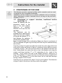
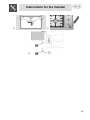
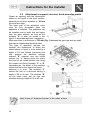
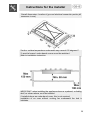
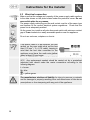
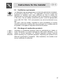
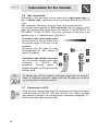
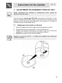
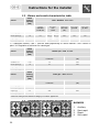
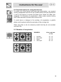
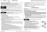
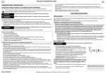
Summary
1
INSTRUCTIONS FOR SAFE AND PROPER USE______________ 20
2
POSITIONING OF THE HOB ______________________________ 22
3
ADJUSTMENT TO DIFFERENT TYPES OF GAS ______________ 29
4
FINAL OPERATIONS ____________________________________ 31
5
USING THE HOB _______________________________________ 32
6
CLEANING AND MAINTENANCE __________________________ 34
THESE INSTRUCTIONS ARE VALID ONLY FOR END USER COUNTRIES WHOSE
IDENTIFICATION SYMBOLS APPEAR ON THE COVER OF THIS MANUAL.
INSTRUCTIONS FOR THE INSTALLER: these are for the qualified
technician who must carry out a suitable check of the gas system,
install the appliance, set it functioning and carry out an inspection test.
INSTRUCTIONS FOR THE USER : these contain user advice,
description of the commands and the correct procedures for cleaning
and maintenance of the appliance.
19
Introduction
1
INSTRUCTIONS FOR SAFE AND PROPER USE
THIS MANUAL IS AN INTEGRAL PART OF THE APPLIANCE AND
THEREFORE MUST BE KEPT IN ITS ENTIRETY AND IN AN ACCESSIBLE
PLACE FOR THE WHOLE WORKING LIFE OF THE HOB. WE ADVISE
READING THIS MANUAL AND ALL THE INSTRUCTIONS THEREIN BEFORE
USING THE HOB. ALSO KEEP THE SERIES OF NOZZLES SUPPLIED.
INSTALLATION MUST BE CARRIED OUT BY QUALIFIED PERSONNEL IN
ACCORDANCE WITH THE REGULATIONS IN FORCE. THIS APPLIANCE IS
INTENDED FOR FOR DOMESTIC USES AND CONFORMS TO EEC
DIRECTIVES CURRENTLY IN FORCE. THE APPLIANCE IS DESIGNED TO
CARRY OUT THE FOLLOWING FUNCTIONS: COOKING AND HEATING
FOOD; ALL OTHER USES ARE TO BE CONSIDERED IMPROPER.
THE MANUFACTURER DECLINES ALL LIABILITY FOR IMPROPER USE .
DO NOT LEAVE THE PACKAGING MATERIALS UNATTENDED IN THE HOME
ENVIRONMENT. SEPARATE THE DIFFERENT WASTE MATERIALS FROM
THE PACKAGING AND DELIVER THEM TO THE NEAREST COLLECTION
CENTRE FOR RECYCLABLE WASTE.
REGULATIONS REQUIRE THAT THE APPLIANCE IS
ACCORDANCE WITH ELECTRICAL SAFETY REGULATIONS.
EARTHED
IN
THE PLUG TO BE CONNECTED TO THE POWER SUPPLY CABLE AND THE
SOCKET MUST BE OF THE SAME TYPE AND MUST CONFORM TO
CURRENT REGULATIONS.
THE POWER SOCKET MUST BE ACCESSIBLE AFTER THE APPLIANCE HAS
BEEN BUILT IN.
NEVER UNPLUG THE APPLIANCE BY PULLING THE POWER SUPPLY
CABLE.
IMMEDIATELY AFTER INSTALLATION, CARRY OUT A BRIEF INSPECTION
TEST OF THE APPLIANCE, FOLLOWING THE INSTRUCTIONS BELOW.
SHOULD THE APPLIANCE NOT FUNCTION, DISCONNECT IT FROM THE
POWER SUPPLY AND CONTACT YOUR NEAREST TECHNICAL ASSISTANCE
CENTRE.
NEVER ATTEMPT TO REPAIR THE APPLIANCE YOURSELF.
ALWAYS CHECK THAT THE CONTROL KNOBS ARE IN THE POSITION
(OFF) WHEN YOU FINISH USING THE HOB.
20
Introduction
THE APPLIANCE DATA PLATE, WITH TECHNICAL DATA, REGISTRATION
NUMBER AND BRAND NAME, IS POSITIONED AT A VISIBLE POINT UNDER
THE SAFETY COVER.
THE DATA PLATE ON THE PROTECTIVE COVER MUST NEVER BE
REMOVED.
DO NOT PUT PANS WITHOUT PERFECTLY PERFECTLY SMOOTH AND FLAT
BOTTOMS ON THE HOB PANSTAND GRIDS.
DO NOT USE COOKING RECEPTACLES THAT EXTEND BEYOND THE
OUTSIDE PERIMETER OF THE HOB.
THE APPLIANCE IS DESIGNED FOR USE BY ADULTS. DO NOT ALLOW
CHILDREN TO GO NEAR OR PLAY WITH IT.
WHEN DISPOSING OF THE APPLIANCE, TAKE IT TO A COLLECTION
CENTRE FOR RECYCLABLE WASTE.
The manufacturer declines all liability for injury to persons or animals
and for damage to property resulting from non-observance of the above
prescriptions or from tampering with any part of the appliance or for the
use of non-original spare parts.
21
Instructions for the installer
2
POSITIONING OF THE HOB
The following operation requires building and/or carpentry work so must
be carried out by a competent tradesman.
Installation can be carried out on various materials such as masonry,
metal, solid wood or plastic laminated wood, as long as they are heatresistant (T 90°C).
2.1
Attachment to support structure, traditional built-in
model (fig. 1)
Create an opening with the
dimensions shown in the
figure in the work surface,
observing
a
minimum
distance of 50 mm from the
rear edge.
This appliance can be
installed next to walls that are
higher than the work surface,
as long as the distance "X" is
kept between the appliance 1)
and the wall, as shown in the
figure, to avoid damage from overheating. Make sure there is a minimum of
750 mm between the gas rings and any shelf that may be installed directly
above them.
Carefully position the gasket provided all around the outer edge of the hole
in the work surface as shown in figure 2, pressing it down lightly to ensure
it adheres properly. The front and rear sides of the gasket must skim the
hole. Having done this, place the hob on top of the gasket and using the
screws and fixing brackets “C” or “D” (depending on the depth of the
worktop – Fig.4) secure the hob to the support structure, ensuring it is
level. The brackets “C” secure the hob to a structure having a depth of 20
to 30 mm. The brackets “D” on the other hand, are for use with worktops
having a depth of 30 to 50 mm.
Carefully trim any excess from edge C (Fig.3) of the gasket. The distances
in figure 2 refer to the hole on the inner side of the gasket.
22
Instructions for the installer
3)
2)
4)
23
Instructions for the installer
2.2
Attachment to support structure, flush-mounting model
Create an opening with the dimensions
shown in the figure in the work surface,
observing a minimum distance of 50 mm
from the rear edge.
The lower part of the protective cover
must be fully accessible when the
appliance is installed. This appliance can
be installed next to walls that are higher
than the work surface, as long as the
distance "X" is kept, as shown in the 1)
figure, to avoid damage from overheating.
Make sure there is a minimum of 750 mm (Fig. 1) between the gas rings and any shelf
that may be installed directly above them.
This type of appliance requires the
worktop, the dimensions of which are
shown shown in figure 2, to be milled to a
depth of 2.5 mm. Before positioning the
hob, position the adhesive sponge
material “E” supplied over the milled
surface (fig. 3). Having done this, place
the hob on the milled surface and using
the screws and fixing brackets “C” or “D”
(depending on the depth of the worktop)
2)
secure the hob to the support structure,
ensuring it is level. The brackets “C”
secure the hob to a structure having a
depth of 20 to 30 mm. The brackets “D”
on the other hand, are for use with
worktops having a depth of 30 to 50 mm.
3)
Apply a layer of “waterproof primer” to the milled surface.
24
Instructions for the installer
Overall dimensions: location of gas and electrical connection points (all
measures in mm).
Caution: surface temperature underneath may exceed 125 degrees C.
To avoid a hazard, under-bench access must be restricted.
Refer to installation instruction
IMPORTANT: when installing the appliance above a cupboard, a dividing
shelf, as shown above, must be installed.
If installed above an under-bench oven, this is not required.
Installation of an oven without cooking fan underneath the hob is
forbidden.
25
Instructions for the installer
2.3
Electrical connection
Make sure that the voltage and capacity of the power supply cable conform
to the data shown on the plate located under the protective cover. Do not
remove this plate for any reason.
The power supply cable plug and the wall socket must be of the same type
and conform to the current electrical system regulations. Check that the
power line is adequately earthed.
On the power line, install an all-pole disconnect switch with minimum contact
gap of 3 mm located at an easily accessible position near the appliance.
Do not use reducers, adapters or shunts.
If the power cable is to be replaced, the wire
section on the new cable must not be less
than 0.75 mm2 ( 3 x 0.75 cable), bearing in
mind that the end tobe connected to the
appliance must have the earth wire (yellowgreen) at least 20 mm longer.
Use only H05V2V2-F cable or similar which has a maximum temperature of
90°C. Any replacement needed should be carried out by a specialised
technician who should make the mains connections according to the
following diagram.
L = brown
N = blue
= yellow-green
The manufacturer declines all liability for injury to persons or animals
and for damage to property resulting from non-observance of the above
prescriptions or from tampering with any part of the appliance.
26
Instructions for the installer
2.4
Ventilation requirements
The appliance may be installed only in rooms with permanent ventilation,
as required by UNI-CIG 7129 / 7131 standards. The room in which the
appliance is installed must have sufficient air flow to satisfy the
requirements of normal gas combustion and of necessary air exchange
in the room. The air intakes, protected by grills, must be appropriately
sized (UNI CIG 7129 / 7131) and placed so as not to be blocked in any
way.
The room must be suitably ventilated to avoid overheating or excess
humidity produced by cooking; after any prolonged use, a window should
be opened or the speed of any fans should be increased.
2.5
Discharge of combustion products
Discharge of combustion products must be guaranteed by means of
hoods connected to a natural draught flue with certain efficiency, or by
means of forced aspiration. An efficient aspiration system requires
careful planning by a qualified specialist, respecting the positions and
distances prescribed by standards. After installation, the installer must
issue a certificate of conformity.
27
Instructions for the installer
2.6
Gas connection
Connection to the gas mains may be made with a rigid copper pipe or
with a flexible pipe conforming to the provisions defined by UNI-CIG
7129.
After connection operations, check for leaks using a soapy solution.
The hob has been inspected for G20 natural gas (2H) at a pressure of 20
mbar. For use with other types of gas, see chapter “3. ADJUSTMENT TO
DIFFERENT TYPES OF GAS. The hose connection at the rear of the
appliance has a ½” internal thread (ISO 228-1).
Connection with rigid copper pipe:
the connection to the gas mains must
not provoke stress of any kind on the
appliance.
Connection may be made by using
biconicaladapter D with insertion of
gasket C supplied.
Connection with flexible steel pipe:
use only flexible stainless steel pipes
conforming
to
UNI-CIG
9891
regulations,
inserting
gasket
C
supplied between the fitting A and the
flexible pipe B.
The flexible pipe must be installed so that pipe length does not exceed 2
meters of maximum extension. Make sure that the pipes do not touch
any moving parts or become crushed.
2.7
Connection to LPG
Use a pressure regulator and make the connection to the tank according
to the provisions of UNI-CIG 7432 and UNI-CIG 7131. Make sure that
feed pressure conforms to the levels shown in the table in paragraph “3.2
Burner and nozzle characteristics table
28
Instructions for the installer
3 ADJUSTMENT TO DIFFERENT TYPES OF GAS
Before performing any cleaning or maintenance work, unplug the
appliance from the mains.
The hob is set for natural gas G20 (2H) at a pressure of 20 mbar. In the
case of functioning with other types of gas the burner nozzles must be
changed and the minimum flame adjusted on the gas taps. To change the
nozzles, proceed as described below.
3.1
1.
2.
3.
4.
Replacement of nozzles on the hob
Remove the grids and all the caps and flame-spreader crowns;
Unscrew the burner nozzles with a 7 mm socket wrench;
Replace the nozzles according to the type of gas to be used (see
paragraph “3.2 Burner and nozzle characteristics table”).
Replace the burners in the correct position.
Nozzles for town gas (G110 – 8 mbar) are available from authorized
assistance centres.
29
Instructions for the installer
3.2
Burner and nozzle characteristics table
Rated
heating
capacity
(kW)
Burner
LPG – G30/G31 30/37 mbar
Nozzle
diameter
1/100 mm
By-pass
mm
1/100
Reduced
flow rate
(W)
Flow rate
g/h G30
Flow rate
g/h G31
Auxiliary (1)
1.05
50
27 (*)
28 (**)
350
76
75
Semi rapid (2)
1.8
65
33 (*)
32 (**)
450
130
128
Rapid (3)
2.3
75
43 (*)
42 (**)
800
166
164
Ultra rapid (4)
3.5
94
1.6
253
250
63
*/**: diameters marked * and ** must be fitted respectively on valves marked * and **shown in
point “4.1 Regulation of minimum for natural gas”.
Rated
heating
capacity
(kW)
Burner
Natural gas – G20 20 mbar
Nozzle diameter
1/100 mm
Reduced flow rate
(W)
Auxiliary (1)
1.05
72
350
Semi rapid (2)
1.8
97
450
Rapid (3)
2.3
103
800
Ultra rapid (4)
3.5
133
1500
Rated
heating
capacity
(kW)
Burner
Town gas – G110 8 mbar
Nozzle diameter
1/100 mm
Reduced flow rate
(W)
Auxiliary (1)
1.05
145
350
Semi rapid (2)
1.8
185
450
Rapid (3)
2.3
220
800
Ultra rapid (4)
3.3
290
1500
Values for town gas are based on category III 1a2H3+ appliances.
3.3
Arrangement of burners on cooking hob
BURNERS
1
2
3
4
30
Auxiliary
Semi rapid
Rapid
Ultra rapid
Instructions for the installer
4 FINAL OPERATIONS
After carrying out the above adjustments, remount in reverse order to the
instructions given in paragraph “3.1 Replacement of nozzles on the hob”.
After adjustment to a different kind of gas from the one for which the
appliance has been tested, replace the plate inside the storage
compartment with one corresponding to the new kind of gas. The label is
available from your nearest Authorised Assistance Centre.
4.1
Regulation of minimum for town gas and natural gas
Light the burner and set it at minimum position.
Remove the knob and turn the regulation screw
inside or next to the gas tap pin (depending on the
model) until you get a suitable minimum flame.
Replace the knob and check burner flame stability:
(when you turn the knob quickly from maximum to
minimum position, the flame should not go out).
Repeat this operation for all the gas taps.
4.2
**
*
Regulation of minimum for LPG
To regulate the minimum for LPG, fully tighten the screw inside or next to
the gas tap pin (depending on the model) in a clockwise direction.
The diameters of the by-passes for each burner are given in table “3.2
Burner and nozzle characteristics table”.
4.3
Lubrication of gas taps
With time it may happen that the gas taps get blocked and hard to turn.
Clean them inside and re-grease them. This operation must be done
by an authorised person.
31
Instructions for the user
5
5.1
USING THE HOB
Ignition of the burners
Before turning on the burners, make sure that the flame-spreader
crowns and respective caps are properly fitted in their housings. Ensure
the flame-spreader holes A are aligned with the ignition plugs and the
thermocouples.
Panstand grid B, available upon request, is intended for use with woks
(Chinese pans).
To prevent damage to the worktop, the hob is equipped with a raised
grid C to position below cooking receptacles that exceed 26 cm in
diameter when used on the side burners.
A symbol next to each knob indicates the relative
burner. The device is fitted with electronic ignition.
Simply press and turn the knob counter-clockwise to
the high flame symbol until the burner is ignited.
In models with safety valve, after ignition, the knob has to be held down
for a few seconds to allow the thermocouple to heat up. The burner
might go off when the knob is released: this means the thermocouple
has not heated up sufficiently.
Wait a few moments and then repeat the operation, holding the knob
down for longer. This operation is not necessary for burners without
thermocouples.
Once the burner is ignited, adjust the flame as required.
Always check that the control knobs are in the position
(off) when you
finish using the hob.
If the burners turn off accidentally, a safety device will trip after about 20
seconds to cut off gas flow (even with the gas tap open).
32
Instructions for the user
5.2 Practical advice for using the burners
For better use of the burners and lower gas consumption, use covered
cooking receptacles that have a flat, smooth bottom and are proportional
in size to the burner to prevent the flame from licking the sides (see
paragraph “5.3 Diameter of receptacles”). When water reaches boiling
point, lower the flame so that it does not boil over.
To avoid burns or damage to the worktop, all receptacles or griddle
plates must be placed within the perimeter of the cooking hob.
When using fats or oils, be extremely careful that they do not overheat
and catch fire.
5.3 Diameter of receptacles
BURNERS
1
2
3
4
Auxiliary
Semi rapid
Rapid
Ultra rapid
Ø min. and max.
(in cm)
12 – 16
16 – 22
18 – 24
20 – 26
33
Instructions for the user
6
CLEANING AND MAINTENANCE
Before any intervention, disconnect the appliance from the mains.
6.1 Cleaning the stainless steel
To keep stainless steel in good condition it should be cleaned regularly
after use. Let it cool first.
6.1.1
Routine daily cleaning
To clean and preserve the stainless steel surfaces, always use only
specific products that do not contain abrasives or chlorine-based acids.
How to use: pour the product on a damp cloth and wipe the surface, rinse
thoroughly and dry with a soft cloth or chamois leather.
6.1.2
Food stains or residues
Under no circumstances must metallic scourers or sharp
scrapers be used: they will damage the surface.
Use normal non-abrasive products for steel, and a wooden or
plastic tool if necessary.
Rinse thoroughly and dry with a soft cloth or chamois leather.
6.2 Cleaning of cooking hob components
To facilitate cleaning, panstand grids, caps, flamespreader crowns and burners are all removable;
wash with warm water and non-abrasive detergent,
taking care to remove allstubborn food residues. Wait
for all parts to be fully dry before remounting. Refit
the caps on the respective flame-spreader crowns,
making sure that notchesA align with burner pins B .
To work well, the ignition plugs and thermocouples must
always be very clean. Check them frequently and clean
them with a wet cloth if necessary. Any dry residue should
be removed with a toothpick or a needle.
34