1
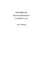
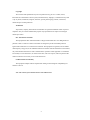
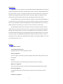
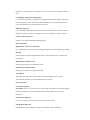
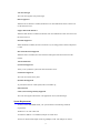
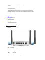
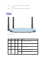
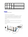
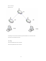
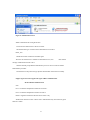
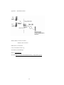
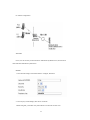
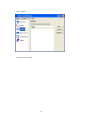
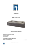
SMCWBR14-GM
Wireless Broadband Router
with MIMO Technology
User’s Manual
1
Copyright
The contents of this publication may not be reproduced in any part or as a whole, stored,
transcribed in an information retrieval system, translated into any language, or transmitted in any form
or by any means, mechanical, magnetic, electronic, optical, photocopying, manual, or otherwise,
without the prior written permission.
Trademarks
All products, company, brand names are trademarks or registered trademarks of their respective
companies. They are used for identification purpose only. Specifications are subject to be changed
without prior notice.
FCC Interference Statement
This equipment has been tested and found to comply with the limits for a Class B digital device
pursuant to Part 15 of the FCC Rules. These limits are designed to provide reasonable protection
against radio interference in a commercial environment. This equipment can generate, use and radiate
radio frequency energy and, if not installed and used in accordance with the instructions in this manual,
may cause harmful interference to radio communications. Operation of this equipment in a residential
area is likely to cause interference, in which case the user, at his own expense, will be required to take
whatever measures are necessary to correct the interference.
CE Declaration of Conformity
This equipment complies with the requirements relating to electromagnetic compatibility, EN
55022/A1 Class B.
Note. The content of user manual will be revised without notice.
2
Table of Contents
Introduction
Features
System Requirements
Package List
Hardware Ports and Buttons
LED Indicators
Getting Started
Configuring Wireless Broadband Router
System Settings
WAN Settings
LAN Settings
Wireless Settings
NAT
Firewall
Dynamic DNS Services
UPnP
System Tools
3
Introduction
Congratulations on your purchase of this outstanding Wireless Broadband Router. This product is
specifically designed for Small Office and Home Office needs. It provides a complete SOHO solution
for Internet surfing, and is easy to configure and operate even for non-technical users. Instructions for
installing and configuring this product can be found in this manual. Before you install and use this
product, please read this manual carefully for fully exploiting the functions of this product.
The SMCWBR14-GM is an ultra slim design and compact size of Wireless Broadband Router. It
is an ideal device for home and office users who need to efficiently and easily surf Internet anytime in
home or office. Additionally, Wireless Broadband Router and fully compliant IEEE 802.11b, 802.11g,
MIMO WLAN device functions let you connect to Local Area Network or Internet easily.
The SMCWBR14-GM offers WLAN mobility for home user and business people to maintain
continuous network connectivity. Home users can stay connected to the network anywhere through a
building without being limited by LAN cables via SMCWBR14-GM’s AP functionality. This device
also has the additional advantage of providing high performance throughput and large coverage range
in wireless network. The SMCWBR14-GM supports the UPnP NAT traversal and users can use any
UPNP software easily without NAT unfriendly problem. Besides it also supports NetBIOS over TCP to
let computers share files in LAN.
Features
Router Basic functions
Auto-sensing Ethernet Switch
Equipped with a 4-port auto-sensing Ethernet switch.
WAN type supported
The router supports some WAN types, Static, Dynamic, PPPoE, PPTP, L2TP, Dynamic IP with
Road Runner.
Firewall
All unwanted packets from outside intruders are blocked to protect your Intranet.
DHCP server supported
All of the networked computers can retrieve TCP/IP settings automatically from this product.
Web-based configuring
Configurable through any networked computer’s web browser using Netscape or Internet
Explorer.
Virtual Server supported
4
Enable you to expose WWW, FTP and other services on your LAN to be accessible to Internet
users.
User-Definable Application Sensing Tunnel
User can define the attributes to support the special applications requiring multiple connections,
like Internet gaming, video conferencing, Internet telephony and so on, then this product can
sense the application type and open multi-port tunnel for it.
DMZ Host supported
Lets a networked computer be fully exposed to the Internet; this function is used when special
application sensing tunnel feature is insufficient to allow an application to function correctly.
Statistics of WAN Supported
Enables you to monitor inbound and outbound packets
Wireless functions
High speed for wireless LAN connection
Up to 54Mbps data rate by incorporating Orthogonal Frequency Division Multiplexing (OFDM).
Roaming
Provides seamless roaming within the IEEE 802.11b (11M) and IEEE 802.11g (54M) WLAN
infrastructure.
IEEE 802.11b compatible (11M)
Allowing inter-operation among multiple vendors.
IEEE 802.11g compatible (54M)
Allowing inter-operation among multiple vendors.
Auto fallback
54M, 48M, 36M, 24M, 18M, 12M, 6M data rate with auto fallback in 802.11g mode.
11M, 5.5M, 2M, 1M data rate with auto fallback in 802.11b mode.
Security functions
Packet filter supported
Packet Filter allows you to control access to a network by analyzing the incoming and outgoing
packets and letting them pass or halting them based on the IP address of the source and
destination.
Domain Filter Supported
Let you prevent users under this device from accessing specific URLs.
URL Blocking Supported
URL Blocking can block hundreds of websites connection by simply a keyword.
5
VPN Pass-through
The router also supports VPN pass-through.
802.1X supported
When the 802.1X function is enabled, the Wireless user must authenticate to this router first to
use the Network service.
Support WPA-PSK and WPA
When the WPA function is enabled, the Wireless user must authenticate to this router first to use
the Network service
SPI Mode Supported
When SPI Mode is enabled, the router will check every incoming packet to detect if this packet
is valid.
DoS Attack Detection Supported
When this feature is enabled, the router will detect and log the DoS attack comes from the
Internet.
Advanced functions
System time Supported
Allow you to synchronize system time with network time server.
E-mail Alert Supported
The router can send its info by mail.
Dynamic dns Supported
At present,the router has 3 ddns.dyndns,TZO.com and dhs.org.
Other functions
UPNP (Universal Plug and Play)Supported
The router also supports this function. The applications: X-box, Msn Messenger.
System Requirements
To start to use the SMCWBR14-GM, your system must have the following minimum
requirements:
Windows 95 / 98 / ME / 2000 / XP.
An Ethernet (10BaseT or 10/100 BaseT) adapter for wired client.
At least one WLAN client adapter of 802.11g(54Mbps) or 802.11b(11Mbps) for wireless
6
connection.
TCP/IP and NetBIOS network protocol installed.
Internet Browser installed.
The SMCWBR14-GM requires an external 12V, 1A power supply which is included in the
SMCWBR14-GM package. For safe operation, please use only the power adapter provided by
SMCWBR14-GM.
Package List
Wireless broadband router
Installation CD-ROM
Power adapter
CAT-5 UTP Fast Ethernet cable
Hardware Ports and Buttons
Rear Panel
Figure 1-1 Rear Panel
Ports:
Port
Description
PWR
Power inlet
7
the port where you will connect your cable (or DSL) modem or
WAN
Ethernet router.
the ports where you will connect networked computers and other
Port 1-4
devices.
LED Indicators
Front Panel
Figure 1-2 Front Panel
LED:
LED
Function
Color
Status
Description
Power
Power
Green
On
Power is being applied to this product.
Green
Blinking
Status is flashed once per second to indicate system is alive.
Green
On
The WAN port is linked.
Blinking
The WAN port is sending or receiving data.
Blinking
Sending or receiving data via wireless
indication
Status
System
status
WAN
WAN port
activity
WLAN
Wireless
Green
activity
8
Link.
Link status Green
On
An active station is connected to the corresponding LAN
1~4
port.
Speed
10/100
Data Rate
Green
Blinking
The corresponding LAN port is sending or receiving data.
On
Data is transmitting in 100Mbps on the corresponding LAN
port.
Reset
To reset system settings to factory defaults
Getting Started
Procedure for Hardware Installation
Decide where to place your Wireless Broadband Router
You can place your Wireless Broadband Router on a desk or other flat surface, or you can mount
it on a wall. For optimal performance, place your Wireless Broadband Router in the center of
your office (or your home) in a location that is away from any potential source of interference,
such as a metal wall or microwave oven. This location must be close to power and network
connection.
Setup LAN connection
Wired LAN connection: connects an Ethernet cable from your computer’s Ethernet port to one of
the LAN ports of this product.
Wireless LAN connection: locate this product at a proper position to gain the best transmit
performance.
9
Figure 2-1 Setup of LAN and WAN connections for this product.
Setup WAN connection
Prepare an Ethernet cable for connecting this product to your cable/xDSL modem or Ethernet
backbone. Figure 2-3 illustrates the WAN connection.
Power on
Connecting the power cord to power inlet and turning the power switch on, this product will
automatically enter the self-test phase. When it is in the self-test phase, the indicators status will
be lighted ON for about 10 seconds, and then status will be flashed 3 times to indicate that the
self-test operation has finished. Finally, the status will be continuously flashed once per second
to indicate that this product is in normal operation.
Make Correct Network Settings of Your Computer
The default IP address of this product is 192.168.2.1, and the default subnet mask is
255.255.255.0. These addresses can be changed on your need, but the default values are used in
this manual. If the TCP/IP environment of your computer has not yet been configured, you can
refer to Appendix A to configure it. For example,
configure IP as 192.168.2.10, subnet mask as 255.255.255.0 and gateway as 192.168.2.1, or
more easier, configure your computers to load TCP/IP setting automatically, that is, via DHCP
server of this product.
After installing the TCP/IP communication protocol, you can use the ping command to check if
your computer has successfully connected to this product. The following example shows the ping
procedure for Windows 95 platforms. First, execute the ping command
ping 192.168.2.1
If the following messages appear:
Pinging 192.168.2.1 with 32 bytes of data:
Reply from 192.168.2.1: bytes=32 time=2ms TTL=64
A communication link between your computer and this product has been successfully established.
Otherwise, if you get the following messages,
Pinging 192.168.2.1 with 32 bytes of data:
Request timed out.
There must be something wrong in your installation procedure. You have to check the following
10
items in sequence:
Is the Ethernet cable correctly connected between this product and your computer?
Configuring Wireless Broadband Router
This product provides Web based configuration scheme that is, configuring by your Web browser,
such as Netscape Communicator or Internet Explorer. This approach can be adopted in any MS
Windows, Macintosh or UNIX based platforms.
Start-up and Log in
11
Activate your browser, and disable the proxy or add the IP address of this product into the
exceptions. Then, type this product’s IP address in the Location (for Netscape) or Address (for
IE) field and press ENTER. For example: http://192.168.2.1.
After the connection is established, you will see the web user interface of this product. There are
two appearances of web user interface: for general users and for system administrator.
To log in as an administrator, enter the system password (the factory setting is ”smcadmin”) in
the System Password field and click on the Log in button. If the password is correct, the web
appearance will be changed into administrator configure mode. As listed in its main menu, there
are several options for system administration.
Status
12
This option provides the function for observing this product’s working status:
WAN Port Status.
If the WAN port is assigned a dynamic IP, there may appear a “Renew” or “Release” button on
the Sidenote column. You can click this button to renew or release IP manually.
Wizard
13
Setup Wizard will guide you through a basic configuration procedure step by step. Set the basic
Wireless Parameters and Press ”Next >”
Setup Wizard - Select Time Zone
14
Select the WAN Access Type
Set your username and password. You might select from the 3 different connection profiles.
Be careful with Always online if you do not have a flatrate-connection!
15
System Settings
Time Zone
Password Settings
16
Enable / Disable Remote Management
WAN Setup
This option is primary to enable this product to work properly. The setting items and the web
17
appearance depend on the WAN type. Choose correct WAN type before you start.
Static IP Address: ISP assigns you a static IP address. WAN IP Address, Subnet Mask,
Gateway, Primary and Secondary DNS: enter the proper setting provided by your ISP.
Dynamic IP Address: Obtain an IP address from ISP automatically. Host Name: optional.
Required by some ISPs, for example, @Home.
Renew IP Forever: this feature enables this product to renew your IP address automatically
when the lease time is expiring-- even when the system is idle.
Dynamic IP Address with Road Runner Session Management.(e.g. Telstra BigPond)
LAN IP Address is the IP address of this product. It must be the default gateway of your
computers. WAN Type is Dynamic IP Address. If the WAN type is not correct, change it!
Host Name: optional. Required by some ISPs, e.g. @Home. Renew IP Forever: this feature
enable this product renew IP address automatically when the lease time is being expired
even the system is in idle state.
PPP over Ethernet: Some ISPs require the use of PPPoE to connect to their services.
PPPoE Account and Password: the account and password your ISP assigned to you. For
security, this field appears blank. If you don't want to change the password, leave it empty.
PPPoE Service Name: optional. Input the service name if your ISP requires it. Otherwise,
leave it blank. Maximum Idle Time: the amount of time of inactivity before disconnecting
your PPPoE session. Set it to zero or enable Auto-reconnect to disable this feature.
Maximum Transmission Unit (MTU): Most ISP offers MTU value to users. The
most common MTU value is 1492.
Connection Control: There are 3 modes to select:
Connect-on-demand: The device will link up with ISP when the clients send
outgoing packets.
Auto-Reconnect(Always-on):The device will link up with ISP until the
connection is established.
Manually: The device will not make the link until someone clicks the
connect-button in the Status-page.
PPTP: Some ISPs require the use of PPTP to connect to their services.
My IP Address and My Subnet Mask: the private IP address and subnet mask your ISP
assigned to you. Server IP Address: the IP address of the PPTP server. PPTP Account and
Password: the account and password your ISP assigned to you. If you don't want to change
18
the password, keep it empty. Connection ID: optional. Input the connection ID if your ISP
requires it. Maximum Idle Time: the time of no activity to disconnect your PPTP session.
Set it to zero or enable Auto-reconnect to disable this feature. If Auto-reconnect is enabled,
this product will connect to ISP automatically, after system is restarted or connection is
dropped.
Connection Control: There are 3 modes to select:
Connect-on-demand: The device will link up with ISP when the clients send
outgoing packets.
Auto-Reconnect (Always-on): The device will link up with ISP until the
connection is established.
Manually: The device will not make the link until someone clicks the
connect-button in the Status-page.
L2TP: Some ISPs require the use of L2TP to connect to their services
First, please check your ISP assigned and Select Static IP Address or Dynamic IP Address.
For example: Use Static: My IP Address and My Subnet Mask: the private IP address and
subnet mask your ISP assigned to you. Server IP Address: the IP address of the PPTP
server. PPTP Account and Password: the account and password your ISP assigned to you.
If you don't want to change the password, keep it empty. Connection ID: optional. Input
the connection ID if your ISP requires it. Maximum Idle Time: the time of no activity to
disconnect your PPTP session. Set it to zero or enable Auto-reconnect to disable this
feature. If Auto-reconnect is enabled, this product will connect to ISP automatically, after
system is restarted or connection is dropped.
Connection Control: There are 3 modes to select:
Connect-on-demand: The device will link up with ISP when the clients send
outgoing packets.
Auto-Reconnect(Always-on):The device will link up with ISP until the
connection is established.
Manually: The device will not make the link until someone clicks the
connect-button in the Status-page.
19
DNS
Set the primary and Secondary DNS server(s) as assigned by your ISP. If you are using different
DNS servers than your ISP, the Internet response-times might be slower and some sites might
become inaccesible.
20
LAN & DHCP Server
The settings of a TCP/IP environment include host IP, Subnet Mask, Gateway, and DNS
configurations. It is not easy to manually configure all the computers and devices in your
network. Fortunately, DHCP Server provides a rather simple approach to handle all these settings.
This product supports the function of DHCP server. If you enable this product’s DHCP server
and configure your computers as “automatic IP allocation” mode, then when your computer is
powered on, it will automatically load the proper TCP/IP settings from this product. The settings
of DHCP server include the following items:
DHCP Server: Choose “Disable” or “Enable.”
IP pool starting Address/ IP pool starting Address: Whenever there is a request,
the DHCP server will automatically allocate an unused IP address from the IP address
pool
to the requesting computer. You must specify the starting and ending address of the IP address
pool.
21
Wireless Settings
Wireless settings allow you to set the wireless configuration items.
Network ID (SSID): Network ID is used for identifying the Wireless LAN (WLAN). Client
stations can roam freely over this product and other Access Points that have the same Network
ID. (The factory setting is “default”)
Channel: The radio channel number. The permissible channels depend on the Regulatory
Domain.
The factory setting is as follow: channel 6 for North America; channel 7 for European (ETSI);
channel 7 for Japan.
WEP Security: Select the data privacy algorithm you want. Enabling the security can protect
your data while it is transferred from one station to another. The standardized IEEE 802.11 WEP
(128 or 64-bit) is used here.
WEP Key 1, 2, 3 & 4: When you enable the 128 or 64 bit WEP key security, please select one
WEP key to be used and input 26 or 10 hexadecimal (0, 1, 2…8, 9, A, B…F) digits.
Pass-phrase Generator: Since hexadecimal characters are not easily remembered, this device
offers a conversion utility to convert a simple word or phrase into hex.
802.1X
Check Box was used to switch the function of the 802.1X. When the 802.1X function is enabled,
the Wireless user must authenticate to this router first to use the Network service.
22
RADIUS Server: IP address or the 802.1X server’s domain-name.
RADIUS Shared Key
Key value shared by the RADIUS server and this router. This key value is consistent with the
key value in the RADIUS server.
WPA-PSK
Select Encryption and Pre-share Key Mode. If you select HEX, you have to fill in 64
hexadecimal (0, 1, 2…8, 9, A, B…F) digits, if ASCII, the length of Pre-share key is from 8 to 63.
Fill in the key, Ex 12345678
23
WPA
Check Box was used to switch the function of the WPA. When the WPA function is enabled, the
Wireless user must authenticate to this router first to use the Network service. RADIUS Server
IP address or the 802.1X server’s domain-name. Encryption and RADIUS Shared Key
If you select HEX, you have to fill in 64 hexadecimal (0, 1, 2…8, 9, A, B…F) digits, if ASCII,
the length of Pre-share key is from 8 to 63.
Key value shared by the RADIUS server and this router. This key value is consistent with the
key value in the RADIUS server.
WPA2-PSK(AES)
Select Encryption and Pre-share Key Mode. If you select HEX, you have to fill in 64
hexadecimal (0, 1, 2…8, 9, A, B…F) digits, if ASCII, the length of Pre-share key is from 8 to 63.
2. Fill in the key, Ex 12345678
WPA2(AES)
Check Box was used to switch the function of the WPA. When the WPA function is enabled, the
Wireless user must authenticate to this router first to use the Network service. RADIUS Server
IP address or the 802.1X server’s domain-name. Encryption and RADIUS Shared Key
If you select HEX, you have to fill in 64 hexadecimal (0, 1, 2…8, 9, A, B…F) digits, if ASCII,
24
the length of Pre-share key is from 8 to 63.
Key value shared by the RADIUS server and this router. This key value is consistent with the
key value in the RADIUS server.
WPA-PSK /WPA2-PSK
Select Encryption and Pre-share Key Mode. If you select HEX, you have to fill in 64
hexadecimal (0, 1, 2…8, 9, A, B…F) digits, if ASCII, the length of Pre-share key is from 8 to 63.
Fill in the key, Ex 12345678
WPA/WPA2
Check Box was used to switch the function of the WPA. When the WPA function is enabled, the
Wireless user must authenticate to this router first to use the Network service. RADIUS Server
IP address or the 802.1X server’s domain-name. Encryption and RADIUS Shared Key
If you select HEX, you have to fill in 64 hexadecimal (0, 1, 2…8, 9, A, B…F) digits, if ASCII,
the length of Pre-share key is from 8 to 63.
Key value shared by the RADIUS server and this router. This key value is consistent with the
key value in the RADIUS server.
WDS(Wireless Distribution System)
WDS operation as defined by the IEEE802.11 standard has been made available. Using WDS it
is possible to wirelessly connect Access Points, and in doing so extend a wired infrastructure to
locations where cabling is not possible or inefficient to implement.
How to setup and work:
AP 1:
AP2:
AP3:
IP:192.168.2.1
IP:192.168.2.253
IP:192.168.2.252
Mac:00-50-18-00-0f-fe
Mac:00-50-18-00-0f-fd
Mac:00-50-18-00-0f-fc
SSID: Default
SSID: Default
SSID: Default
Channel:11
Channel: 11
Channel:11
DHCP Server: Enable
25
Blue Line: Wireless
Black Line: Wire
If the Settings are ok, the client1 and client2 can get IP from DHCP server. Of AP1.Then Client1
and Client2 can get information each other.
AP1 Setting:
AP1ÅÆ AP2 (Remote Mac: 00-50-18-00-0f-fd)
AP1ÅÆ AP3 (Remote Mac: 00-50-18-00-0f-fc)
26
AP2 Setting:
AP2ÅÆ AP1 (Remote Mac: 00-50-18-00-0f-fe)
AP3 Setting:
AP3ÅÆ AP1 (Remote Mac: 00-50-18-00-0f-fe)
27
NAT
Virtual Server
This product’s NAT firewall filters out unrecognized packets to protect your Intranet, so all hosts
behind this product are invisible to the outside world. If you wish, you can make some of them
accessible by enabling the Virtual Server Mapping.
A virtual server is defined as a Service Port, and all requests to this port will be redirected to the
computer specified by the Server IP. Virtual Server can work with Scheduling Rules, and
give user more flexibility on Access control. For Detail, please refer to Scheduling Rule.
For example, if you have an FTP server (port 21) at 192.168.2.1, a Web server (port 80) at
192.168.2.2, and a VPN server at 192.168.2.6, then you need to specify the following virtual
server mapping table:
Service Port
Server IP
Enable
21
192.168.2.1
V
80
192.168.2.2
V
1723
192.168.2.6
V
Special Application
28
Some applications require multiple connections, like Internet games, Video conferencing,
Internet telephony, etc. Because of the firewall function, these applications cannot work with a
pure NAT router. The Special Applications feature allows some of these applications to work
with this product. If the mechanism of Special Applications fails to make an application work,
try setting your computer as the DMZ host instead.
Trigger: the outbound port number issued by the application..
Incoming Ports: when the trigger packet is detected, the inbound packets sent to the specified
port numbers are allowed to pass through the firewall.
This product provides some predefined settings Select your application and click Copy to to add
the predefined setting to your list.
Note! At any given time, only one PC can use each Special Application tunnel.
29
Firewall
Parental Control
This option lets you enable / disable web sites / services by setting up rules.
30
MAC Filter
This option lets you control the Wireless clients connectiong to your MIMO Wireless Router.
Each on of them will be checked before letting them connect wirelessly. This option does not
work for wired client PCs. You can select from two different policies:
Allow: will let all computers access the network, except the ones appearing on the list
Block: will not let any computers accessing the network unless they are on the list.
31
URL (Website) Blocking
URL Blocking will block LAN computers to connect to pre-defined Websites.
The major difference between “Domain filter” and “URL Blocking” is Domain filter require user
to input suffix (like .com or .org, etc), while URL Blocking require user to input a keyword only.
In other words, Domain filter can block specific website, while URL Blocking can block
hundreds of websites by simply a keyword.
URL Blocking Enable
Check, if you want to enable URL Blocking.
URL
If any part of the Website's URL matches the pre-defined word, the connection will be
blocked.
For example, you can use pre-defined word "sex" to block all websites if their URLs
contain pre-defined word "sex".
Enable
Check to enable each rule.
32
Advanced Firewall Settings
Enable the Advanced Firewall Protection if you want:
Hacker attack monitoring and logging
Advanced System Log
Email Notification
Enable the Discard Ping from WAN option if you don’t want to be seen on the Internet.
You can also enable / disable VPN protocols to pass through your NAT Firewall
Set up your E-Mail address and servers to get the notification emails on the desired account.
33
Demilitarized Zone (DMZ)
This option lets you open all ports to one workstation behind your Router. Be careful with this
option, because it let’s everybody access that particular PC from everywhere.
34
Dynamic DNS Services
To host your server on a changing IP address, you have to use dynamic domain name service
(DDNS).
So that anyone wishing to reach your host only needs to know the name of it. Dynamic DNS will
map the name of your host to your current IP address, which changes each time you connect your
Internet service provider.
Before you enable Dynamic DNS, you need to register an account on one of these Dynamic
DNS servers that we list in provider field.
To enable Dynamic DNS click the check box next to Enable in the DDNS field.
Next you can enter the appropriate information about your Dynamic DNS Server.
You have to define:
Provider
Host Name
Username/E-mail
Password/Key
You will get this information when you register an account on a Dynamic DNS server.
After Dynamic DNS setting is configured, click the Apply button.
35
UPnP
The Universal Plug and Play architecture offers pervasive peer-to-peer network connectivity of
PCs of all form factors, intelligent appliances, and wireless devices. UPnP enables seamless
proximity networking in addition to control and data transfer among networked devices in the
home, office and everywhere in between.
36
Configuration Tools
Firmware Upgrade
You can upgrade firmware by clicking Apply button.
37
Backup Settings
You can backup your settings by clicking the Backup Setting button and save it as a bin file.
Once you want to restore these settings, please click Firmware Upgrade button and use the bin
file you saved.
Reset To Factory Defaults
You can also reset this product to factory default by clicking the Reset to default button.
38
Appendix A
TCP/IP Configuration for Windows 95/98
This section introduces you how to install TCP/IP protocol into your personal computer. And
suppose you have been successfully installed one network card on your personal computer. If not,
please refer to your network card manual. Moreover, the Section B.2 tells you how to set TCP/IP
values for working with this NAT Router correctly.
A.1 Install TCP/IP Protocol into Your PC
Click Start button and choose Settings, then click Control Panel.
Double click Network icon and select Configuration tab in the Network window.
Click Add button to add network component into your PC.
Double click Protocol to add TCP/IP protocol.
Select Microsoft item in the manufactures list. And choose TCP/IP in the Network Protocols.
Click OK button to return to Network window.
39
The TCP/IP protocol shall be listed in the Network window. Click OK to complete the install
procedure and restart your PC to enable the TCP/IP protocol.
A.2 Set TCP/IP Protocol for Working with NAT Router
Click Start button and choose Settings, then click Control Panel.
Double click Network icon. Select the TCP/IP line that has been associated to your network card
in the Configuration tab of the Network window.
40
Click Properties button to set the TCP/IP protocol for this NAT Router.
Now, you have two setting methods:
41
Select Obtain an IP address automatically in the IP Address tab.
Don’t input any value in the Gateway tab.
42
Choose Disable DNS in the DNS Configuration tab.
Configure IP manually
Select Specify an IP address in the IP Address tab. The default IP address of this product is
192.168.2.1. So please use 192.168.2.xxx (xxx is between 1 and 253) for IP Address field and
255.255.255.0 for Subnet Mask field.
43
In the Gateway tab, add the IP address of this product (default IP is 192.168.2.1) in the New
gateway field and click Add button.
In the DNS Configuration tab, add the DNS values which are provided by the ISP into DNS
44
Server Search Order field and click Add button.
Appendix B 802.1x Setting
Figure 1: Testing Environment (Use Windows 2000 Radius Server)
1 Equipment Details
PC1:
45
Microsoft Windows XP Professional without Service Pack 1.
D-Link DWL-650+ wireless LAN adapter
Driver version: 3.0.5.0 (Driver date: 03.05.2003)
PC2:
Microsoft Windows XP Professional with Service Pack 1a.
Z-Com XI-725 wireless LAN USB adapter
Driver version: 1.7.29.0 (Driver date: 10.20.2001)
Authentication Server: Windows 2000 RADIUS server with Service Pack 3 and HotFix
Q313664.
Note. Windows 2000 RADIUS server only supports PEAP after upgrade to service pack 3 and
HotFix Q313664 (You can get more information from
http://support.microsoft.com/default.aspx?scid=kb; en-us;313664)
2 DUT
Configuration:
Enable DHCP server.
WAN setting: static IP address.
LAN IP address: 192.168.2.1/24.
Set RADIUS server IP.
Set RADIUS server shared key.
Configure WEP key and 802.1X setting.
The following test will use the inbuilt 802.1X authentication method such as ,EAP_TLS,
PEAP_CHAPv2(Windows XP with SP1 only), and PEAP_TLS(Windows XP with SP1 only) using the
Smart Card or other Certificate of the Windows XP Professional.
3. DUT and Windows 2000 Radius Server Setup
Setup Windows 2000 RADIUS Server
We have to change authentication method to MD5_Challenge or using smart
card or other certificate on RADIUS server according to the test condition.
Setup DUT
46
Enable the 802.1X (check the “Enable checkbox“).
Enter the RADIUS server IP.
Enter the shared key. (The key shared by the RADIUS server and DUT).
We will change 802.1X encryption key length to fit the variable test
condition.
Setup Network adapter on PC
1. Choose the IEEE802.1X as the authentication method. (Fig 2)
Note.
Figure 2 is a setting picture of Windows XP without service pack 1. If users upgrade to service
pack 1, then they can’t see MD5-Challenge from EAP type list any more, but they will get a new
Protected EAP (PEAP) option.
2. Choose MD5-Challenge or Smart Card or other Certificate as the EAP type.
3. If choosing use smart card or the certificate as the EAP type, we select to use a certificate on
this computer. (Fig 3)
4. We will change EAP type to fit the variable test condition.
47
Figure 2: Enable IEEE 802.1X access control
48
Figure 3: Smart card or certificate properties
4. Windows 2000 RADIUS server Authentication testing:
4.1DUT authenticate PC1 using certificate. (PC2 follows the same test procedures.)
Download and install the certificate on PC1. (Fig 4)
PC1 choose the SSID of DUT as the Access Point.
Set authentication type of wireless client and RADIUS server both to
EAP_TLS.
Disable the wireless connection and enable again.
5. The DUT will send the user's certificate to the RADIUS server, and
then send the
message of authentication result to PC1. (Fig 5)
6. Windows XP will prompt that the authentication process is success or fail and end the
authentication procedure. ( Fig 6)
7. Terminate the test steps when PC1 get dynamic IP and PING remote host successfully.
49
Figure 4: Certificate information on PC1
Figure 5: Authenticating
50
Figure 6: Authentication success
4.2 DUT authenticate PC2 using PEAP-TLS.
PC2 choose the SSID of DUT as the Access Point.
Set authentication type of wireless client and RADIUS server both to
PEAP_TLS.
Disable the wireless connection and enable again.
The DUT will send the user's certificate to the RADIUS server, and
then send the
message of authentication result to PC2.
Windows XP will prompt that the authentication process is success or fail and end the
authentication procedure.
Terminate the test steps when PC2 get dynamic IP and PING remote host successfully.
Support Type: The router supports the types of 802.1x Authentication:
PEAP-CHAPv2 and PEAP-TLS.
Note.
PC1 is on Windows XP platform without Service Pack 1.
PC2 is on Windows XP platform with Service Pack 1a.
PEAP is supported on Windows XP with Service Pack 1 only.
Windows XP with Service Pack 1 allows 802.1x authentication only when data encryption
function is enable.
51
Appendix C WPA-PSK and WPA
Wireless Router: LAN IP: 192.168.2.1
WAN IP: 192.168.122.216
Radius Server: 192.168.122.1
UserA : XP Wireless Card:Ti-11g
Tool: Odyssey Client Manager
Refer to: www.funk.com
Download: http://www.funk.com/News&Events/ody_c_wpa_preview_pn.asp
52
Or Another Configuration:
WPA-PSK
In fact, it is not necessary for this function to authenticate by Radius Server, the client and
wireless Router authenticate by themselves.
Method1:
1. Go to the Web manager of Wireless Router to configure, like below:
2. Go to Odyssey Client Manager, first choose “Network”
Before doing that, you should verify if the software can show the wireless card.
53
Open “Adapters”
3. Add and edit some settings:
54
4. Back to Connection:
Then Select “Connect to network” You will see:
Method2:
55
1. First, patch windows XP and have to install “Service package 1”
Patch:
http://www.microsoft.com/downloads/details.aspx?displaylang=en&FamilyID=5039ef4a-61e0-4c44-9
4f0-c25c9de0ace9
2. Then reboot.
3. Setting on the router and client:
Router:
Client:
Go to “Network Connection” and select wireless adapter.
Choose “View available Wireless Networks” like below:
AdvancedÆ choose “123kk”
56
57
WPA:
For this function, we need the server to authenticate. This function is like 802.1x.
The above is our environment:
Method 1:
1. The UserA or UserB have to get certificate from Radius, first.
http://192.168.122.1/certsrv
account : fae1
passwd : fae1
58
2. Then, Install this certificate and finish.
3. Go to the Web manager of Wireless Router to configure, like below:
4. Go to Odyssey Client Manager, choose “Profiles” and Setup Profile name as “1”
59
Login name and password are fae1 and fae1.
Remember that you get certificate from Radius in Step1.
5. Then Choose “certificate” like above.
60
61
6. Then go to Authentication and first Remove EAP/ TLS and Add EAP/TLS again.
62
7. Go “Network” and Select “1” and ok
63
8. Back to Connection and Select “123kk.
If successfully, the wireless client has to authenticate with Radius Server, like below:
9.Result:
Method 2:
1. The UserA or UserB have to get certificate from Radius,first.
64
http://192.168.122.1/certsrv
account:fae1
passwd:fae1
2. Then Install this certificate and finish.
3. Setting on the router and client:
Router:
65
Client:
Go to “Network Connection” and select wireless adapter.
Choose “View available Wireless Networks” like below:
AdvancedÆ choose “123kk”
Select “WirelessCA and Enable” in Trusted root certificate authority:
66
Then, if the wireless client wants to associate, it has to request to authenticate.
Appendix D FAQ and Troubleshooting
Reset to factory Default
There are 2 methods to reset to default.
Restore with RESET button
First, turn off the router and press the RESET button in. And then, power on the router and push
the RESET button down until the Status LED start flashing, then remove the finger. If LED flashes
about 8 times, the RESTORE process is completed. However, if LED flashes 2 times, repeat.
2. Restore directly when the router power on
First, push the RESET button about 5 seconds (M1 will start flashing about 5 times), remove the
finger
. The RESTORE process is completed.
67
TECHNICAL SUPPORT
From U.S.A. and Canada (24 hours a day, 7 days a week)
(800) SMC-4-YOU
Phn: (949) 679-8000
Fax: (949) 679-1481
ENGLISH
Technical Support information available at www.smc.com
FRENCH
Informations Support Technique sur www.smc.com
DEUTSCH
Technischer Support und weitere Information unter www.smc.com
SPANISH
En www.smc.com Ud. podrá encontrar la información relativa a servicios de
soporte técnico
DUTCH
Technische ondersteuningsinformatie beschikbaar op www.smc.com
PORTUGUES
Informações sobre Suporte Técnico em www.smc.com
SWEDISH
Information om Teknisk Support finns tillgängligt på www.smc.com
INTERNET
E-mail address: [email protected]
DRIVER UPDATES
http://www.smc.com/index.cfm?action=tech_support_drivers_downloads
WORLD WIDE WEB
http://www.smc.com/
Model Number: SMCWBR14-GM
38 Tesla
Irvine, CA 92618
Phone: (949) 679-8000