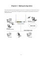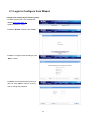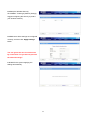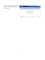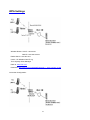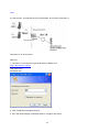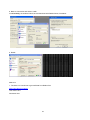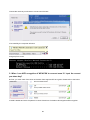
1
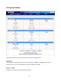
1 Copyright Copyright 2010 PLANET Technology Corp. All rights reserved. No part of this publication may be reproduced, transmitted, transcribed, stored in a retrieval system, or translated into any language or computer language, in any form or by any means, electronic, mechanical, magnetic, optical, chemical, manual or otherwise, without the prior written permission of PLANET. PLANET makes no representations or warranties, either expressed or implied, with respect to the contents hereof and specifically disclaims any warranties, merchantability or fitness for any particular purpose. Any software described in this manual is sold or licensed "as is". Should the programs prove defective following their purchase, the buyer (and not this company, its distributor, or its dealer) assumes the entire cost of all necessary servicing, repair, and any incidental or consequential damages resulting from any defect in the software. Further, this company reserves the right to revise this publication and to make changes from time to time in the contents hereof without obligation to notify any person of such revision or changes. All brand and product names mentioned in this manual are trademarks and/or registered trademarks of their respective holders. Federal Communication Commission Interference Statement This equipment has been tested and found to comply with the limits for a Class B digital device, pursuant to Part 15 of FCC Rules. These limits are designed to provide reasonable protection against harmful interference in a residential installation. This equipment generates, uses, and can radiate radio frequency energy and, if not installed and used in accordance with the instructions, may cause harmful interference to radio communications. However, there is no guarantee that interference will not occur in a particular installation. If this equipment does cause harmful interference to radio or television reception, which can be determined by turning the equipment off and on, the user is encouraged to try to correct the interference by one or more of the following measures: 1. Reorient or relocate the receiving antenna. 2. Increase the separation between the equipment and receiver. 3. Connect the equipment into an outlet on a circuit different from that to which the receiver is connected. 4. Consult the dealer or an experienced radio technician for help. FCC Caution: To assure continued compliance, (example-use only shielded interface cables when connecting to computer or peripheral devices) any changes or modifications not expressly approved by the party responsible for compliance could void the user’s authority to operate the equipment. This device complies with Part 15 of the FCC Rules. Operation is subject to the Following two conditions: (1) This device may not cause harmful interference, and (2) this Device must accept any interference received, including interference that may cause undesired operation. 2 Federal Communication Commission (FCC) Radiation Exposure Statement This equipment complies with FCC radiation exposure set forth for an uncontrolled environment. In order to avoid the possibility of exceeding the FCC radio frequency exposure limits, human proximity to the antenna shall not be less than 20 cm (8 inches) during normal operation. CE mark Warning This is a class B device, in a domestic environment; this product may cause radio interference, in which case the user may be required to take adequate measures. Energy Saving Note of the Device This power required device does not support Stand by mode operation. For energy saving, please remove the DC-plug or push the hardware Power Switch to OFF position to disconnect the device from the power circuit. Without remove the DC-plug or switch off the device, the device will still consuming power from the power circuit. In the view of Saving the Energy and reduce the unnecessary power consuming, it is strongly suggested to switch off or remove the DC-plug for the device if this device is not intended to be active. R&TTE Compliance Statement This equipment complies with all the requirements of DIRECTIVE 1999/5/CE OF THE EUROPEAN PARLIAMENT AND THE COUNCIL OF 9 March 1999 on radio equipment and telecommunication terminal Equipment and the mutual recognition of their conformity (R&TTE). The R&TTE Directive repeals and replaces in the directive 98/13/EEC (Telecommunications Terminal Equipment and Satellite Earth Station Equipment) As of April 8, 2000. Safety This equipment is designed with the utmost care for the safety of those who install and use it. However, special attention must be paid to the dangers of electric shock and static electricity when working with electrical equipment. All guidelines of this and of the computer manufacture must therefore be allowed at all times to ensure the safe use of the equipment. National Restrictions This device is intended for home and office use in all EU countries (and other countries following the EU directive 1999/5/EC) without any limitation except for the countries mentioned below: 3 Country Restriction Bulgaria None Reason/remark General authorization required for outdoor use and public service France Outdoor use limited to 10 mW Military Radiolocation use. Refarming of the 2.4 GHz band e.i.r.p. within the band has been ongoing in recent years to allow current relaxed 2454-2483.5 MHz regulation. Full implementation planned 2012 If used outside of own premises, general authorization is Italy None required General authorization required for network and service Luxembourg None supply(not for spectrum) This subsection does not apply for the geographical area Norway Implemented within a radius of 20 km from the centre of Ny-Ålesund Russian Federation None Only for indoor applications WEEE Regulation To avoid the potential effects on the environment and human health as a result of the presence of hazardous substances in electrical and electronic equipment, end users of electrical and electronic equipment should understand the meaning of the crossed-out wheeled bin symbol. Do not dispose of WEEE as unsorted municipal waste and have to collect such WEEE separately. Revision User’s Manual for PLANET 802.11n Wireless Gigabit Broadband Router Model: WNRT-632 Rev: 1.1 (July. 2011) 4 Table of Contents Chapter 1 Introduction ................................................................................................... 7 1.1 Packing Contents ................................................................................................7 1.2 Spec Summary Table ..........................................................................................8 1.3 Hardware Configuration ......................................................................................9 1.4 LED indicators................................................................................................... 11 1.5 Procedure for Hardware Installation..................................................................12 Chapter 2 Making Configuration .................................................................................. 14 2.1 Login to Configure from Wizard ........................................................................15 2.2 System Status ...................................................................................................19 2.3 Advanced ..........................................................................................................20 2.3.1 Basic Setting ...........................................................................................20 2.3.1.1 Primary Setup – WAN Type, Virtual Computers............................ 21 2.3.1.2 DHCP Server ................................................................................ 25 2.3.1.3 Wireless ........................................................................................ 26 2.3.1.4 Change Password ........................................................................ 31 2.3.2 Forwarding Rules....................................................................................32 2.3.2.1 Virtual Server ................................................................................ 32 2.3.2.2 Special AP..................................................................................... 33 2.3.2.3 Miscellaneous Items ..................................................................... 34 2.3.3 Security Settings .....................................................................................35 2.3.3.1 Packet Filters ................................................................................ 36 2.3.3.2 Domain filters................................................................................ 41 2.3.3.3 URL Blocking ................................................................................ 43 2.3.3.4 Internet Access Control................................................................. 45 2.3.3.5 Miscellaneous Items ..................................................................... 52 2.3.4 Advanced Settings ..................................................................................53 2.3.4.1 System Time ................................................................................. 54 2.3.4.2 System Log................................................................................... 55 2.3.4.3 DDNS Service............................................................................... 56 2.3.4.4 SNMP ........................................................................................... 57 2.3.4.5 Routing ......................................................................................... 58 2.3.4.6 Schedule Rule .............................................................................. 60 2.3.4.7 QoS Rule ...................................................................................... 61 2.3.5 Toolbox ...................................................................................................62 2.3.5.1 View Log ....................................................................................... 62 2.3.5.2 Firmware Upgrade ........................................................................ 63 5 2.3.5.3 Backup Setting.............................................................................. 63 2.3.5.4 Reset to default............................................................................. 64 2.3.5.5 Reboot .......................................................................................... 64 2.3.5.6 Miscellaneous Items ..................................................................... 65 Appendices and Index.................................................................................................... 66 802.1x Setting .........................................................................................................66 WPA Settings ..........................................................................................................71 FAQ and Troubleshooting .............................................................................................. 79 What can I do when I have some trouble at the first time? ..............................79 How do I connect router by using wireless?.....................................................81 6 C Chhaapptteerr 11 IInnttrroodduuccttiioonn Thank you for purchasing WNRT-632. This manual guides you on how to install and properly use the WNRT-632 in order to take full advantage of its features. 1.1 Packing Contents Make sure that you have the following items: WNRT-632 x 1 Power Adapter x 1 Ethernet Cable x 1 CD x 1 (Quick Installation Guide and User’s Manual) Quick Installation Guide x 1 Note: If any of the above items are missing, please contact your supplier for support. 7 1.2 Spec Summary Table Device Interface WNRT-632 Ethernet WAN RJ-45 port, 10/100/1000Mbps, auto-MDI/MDIX 1 Ethernet LAN RJ-45 port, 10/100/1000Mbps, auto-MDI/MDIX 4 Antenna 3dBi detachable antenna 2 WPS Button For WPS connection 1 Wireless Enable/disable LED Indication Power Jack To enable or disable Wireless Radio Power/Status / WAN / LAN1 ~ LAN4/ Wi-Fi DC Power Jack, powered via external DC 12V/1A switching power adapter 1 ● 1 Wireless LAN (WiFi) Standard IEEE 802.11b/g/n compliance ● SSID SSID broadcast or in stealth mode ● Channel Auto-selection, manually ● Security WEP, WPA, WPA-PSK, WPA2, WPA2-PSK ● WPS WPS (Wi-Fi Protected Setup) ● WMM WMM (Wi-Fi Multimedia) ● Ethernet WAN PPPoE, DHCP client, Static IP, PPTP, L2TP ● WAN Connection Auto-reconnect, dial-on-demand, manually ● Functionality One-to-Many NAT Virtual server, special application, DMZ, Super DMZ (IP Pass through) ● NAT Session Support NAT session 20000 SPI Firewall IP/Service filter, URL blocking, MAC control ● DoS Protection DoS (Deny of Service) detection and protection ● Routing Protocol Static route, dynamic route (RIP v1/v2) ● Management SNMP, UPnP IGD, syslog, DDNS ● Administration Web-based UI, remote login, backup/restore setting ● Performance NAT up to 700Mbps and Wireless up to150Mbps 8 Environment & Certification Package dimension (W x D x H) (mm) 245 x 207 x 60 Package weight (gross weight) (g) 674 Operation Temp. Temp.: 0~40°C, Humidity 10%~90% non-condensing ● Storage Temp. Temp.: -10~70°C, Humidity: 0~95% non-condensing ● EMI Certification CE/FCC compliance ● RoHS RoHS compliance ● Package Information 1.3 Hardware Configuration Figure 2-1 Front Panel WLAN LED WPS Button Note: WAN LED Power LED Status LED LED1~4 for LAN1~4 Reset = Press Wi-Fi on/off and WPS buttons simultaneously about 5 sec. 9 WiFi on/off Button Figure 2-2 Rear Panel Antenn Power LAN 1~4 WAN 10 Power 1.4 LED indicators LED status Description Status Green in flash Device status is working. WAN LED Green RJ45 cable is plugged Green in flash Data access Green RJ45 cable is plugged Green in flash Data access Green WLAN is on Green in flash Data access Green in fast flash Device is in WPS PBC mode Green in dark Wi-Fi Radio is disabled LAN LED WiFi LED 11 1.5 Procedure for Hardware Installation Step 1. Attach the antenna. 1.1. Remove the antenna from its plastic wrapper. 1.2. Screw the antenna in a clockwise direction to the back panel of the unit. 1.3. Once secured, position the antenna upward at its connecting joint. This will ensure optimal reception. 1.Turn off the Power Switch first. Step 2 Insert the Ethernet cable into LAN Port: Insert the Ethernet patch cable into LAN port on the back panel of Router, and an available Ethernet port on the network adapter in the computer you will use to configure the unit. 12 Step 3 Insert the Ethernet patch cable into Wired WAN port: Insert the Ethernet patch cable form DSL Modem into Wired WAN port on the back panel of Router. Step 4. Power on Router: 4.1. Connect the power adapter to the receptor on the back panel of your Router and Push Power switch Step 5. Complete the setup. 5.1. When complete, the Status LED will flash. 13 C Chhaapptteerr 22 M Maakkiinngg C Coonnffiigguurraattiioonn This product provides Web based configuration scheme, that is, configuring by your Web browser, such as Mozilla Firefox or or Internet Explorer. This approach can be adopted in any MS Windows, Macintosh or UNIX based platforms. 14 2.1 Login to Configure from Wizard Configure the settings by the following steps: 2.1 Open web browser, type the default IP address (http://192.168.0.1) System Password: “admin” 2.2 Select “Wizard”, and then click “Enter”. 2.3 Start to configure Internet setting by click “Next >” button. 2.4 Modify the Old Password by entering a new one. Click “Next >” button if you don’t want to change the password. 15 2.5 Select “Auto Detecting WAN Type” and then click “Next >” button. 2.6 Click “Next >” to continue the setting. Example, the Dynamic WAN type is detected. 2.7 Modify the Wireless settings. Click “Next >” if setting by default. (Strongly suggest changing the SSID to protect your wireless network.) 16 2.8 Setup the Wireless Security. Click “Next >” if setting by default. (Strongly suggest configuring the security to protect your wireless network.) 2.9 Make sure all the settings are configured correctly, and then click “Apply Settings” button. You can ignore the wan connection test by uncheck the “Do you want to proceed the network testing?” 2.10 Wait for the system applying the settings automatically. 17 2.11 Click “Finish” to complete the Setup. Or you can click “Configure Again” to setup the wizard again. 18 2.2 System Status This option provides the function for observing this product’s working status: WAN Status: If the WAN port is assigned a dynamic IP, there may appear a “Renew” or “Release” button on the Sidenote column. You can click this button to renew or release IP manually. Statistics of WAN: Enables you to monitor inbound and outbound packets 19 2.3 Advanced 2.3.1 Basic Setting Please Select “Advanced Setup” to Setup 20 2.3.1.1 Primary Setup – WAN Type, Virtual Computers Click “Change” 21 This option is primary to enable this product to work properly. The setting items and the web appearance depend on the WAN type. Choose correct WAN type before you start. 1. LAN IP Address: the local IP address of this device. The computers on your network must use the LAN IP address of your product as their Default Gateway. You can change it if necessary. 2. WAN Type: WAN connection type of your ISP. You can click Change button to choose a correct one from the following four options: A. Static IP Address: ISP assigns you a static IP address. B. Dynamic IP Address: Obtain an IP address from ISP automatically. C. Dynamic IP Address: Telstra BigPond (Australia's ISP) D. PPP over Ethernet: Some ISPs require the use of PPPoE to connect to their services. E. PPTP: Some ISPs require the use of PPTP to connect to their services. F. L2TP: Some ISPs require the use of L2TP to connect to their services G. Russia PPPoE(Dual Access): Russia PPP over Ethernet(Dual Access) is a common connection method used for XDSL. H. Russia PPTP(Dual Access): Russia PPP Tunneling(Dual Access) can support multi-protocol Virtual Private Network(VPN). Static IP Address: ISP assigns you a static IP address: WAN IP Address, Subnet Mask, Gateway, Primary and Secondary DNS: enter the proper setting provided by your ISP. Dynamic IP Address: Obtain an IP address from ISP automatically. Host Name: optional. Required by some ISPs, for example, @Home. Renew IP Forever: this feature enables this product to renew your IP address automatically when the lease time is expiring-- even when the system is idle. 22 PPP over Ethernet: Some ISPs require the use of PPPoE to connect to their services. PPPoE Account and Password: the account and password your ISP assigned to you. For security, this field appears blank. If you don't want to change the password, leave it empty. PPPoE Service Name: optional. Input the service name if your ISP requires it. Otherwise, leave it blank. Maximum Idle Time: the amount of time of inactivity before disconnecting your PPPoE session. Set it to zero or enable Auto-reconnect to disable this feature. Maximum Transmission Unit (MTU): Most ISP offers MTU value to users. The most common MTU value is 1492. Connection Control: There are 3 modes to select: Connect-on-demand: The device will link up with ISP when the clients send outgoing packets. Auto-Reconnect (Always-on): The device will link with ISP until the connection is established. Manually: The device will not make the link until someone clicks the connect-button in the Status-page. PPTP: Some ISPs require the use of PPTP to connect to their services First, please check your ISP assigned and Select Static IP Address or Dynamic IP Address. My IP Address and My Subnet Mask: the private IP address and subnet mask your ISP assigned to you. Server IP Address: the IP address of the PPTP server. PPTP Account and Password: the account and password your ISP assigned to you. If you don't want to change the password, keep it empty. Connection ID: optional. Input the connection ID if your ISP requires it. Maximum Idle Time: the time of no activity to disconnect your PPTP session. Set it to zero or enable Auto-reconnect to disable this feature. If Auto-reconnect is enabled, this product will connect to ISP automatically, after system is restarted or connection is dropped. Connection Control: There are 3 modes to select: Connect-on-demand: The device will link up with ISP when the clients send outgoing packets. Auto-Reconnect (Always-on): The device will link with ISP until the connection is established. Manually: The device will not make the link until someone clicks the connect-button in the Status-page. L2TP: Some ISPs require the use of L2TP to connect to their services First, please check your ISP assigned and Select Static IP Address or Dynamic IP Address. For example: Use Static My IP Address and My Subnet Mask: the private IP address and subnet mask your ISP assigned to you. Server IP Address: the IP address of the PPTP server. PPTP Account and Password: the account and password your ISP assigned to you. If you don't want to change the password, keep it empty. Connection ID: optional. Input the connection ID if your ISP requires it. Maximum Idle Time: the time of no activity to disconnect your PPTP session. Set it to zero or enable 23 Auto-reconnect to disable this feature. If Auto-reconnect is enabled, this product will connect to ISP automatically, after system is restarted or connection is dropped. Connection Control: There are 3 modes to select: Connect-on-demand: The device will link up with ISP when the clients send outgoing packets. Auto-Reconnect (Always-on): The device will link with ISP until the connection is established. Manually: The device will not make the link until someone clicks the connect-button in the Status-page. Russia PPPoE(Dual Access) This mode only activate for Russia ISP that support dual layer Access to the Internet. Please check with your ISP for the detail setting. Russia PPTP(Dual Access) This mode only activate for Russia ISP that support dual layer Access to the Internet. Please check with your ISP for the detail setting. Virtual Computers (Only for Static and dynamic IP address Wan type) Virtual Computer enables you to use the original NAT feature, and allows you to setup the one-to-one mapping of multiple global IP address and local IP address. Global IP: Enter the global IP address assigned by your ISP. Local IP: Enter the local IP address of your LAN PC corresponding to the global IP address. Enable: Check this item to enable the Virtual Computer feature. 24 2.3.1.2 DHCP Server 1. DHCP Server: Choose “Disable” or “Enable.” 2. Lease time: This is the length of time that the client may use the IP address it has been assigned by dhcp server. 3. IP pool starting Address/ IP pool starting Address: Whenever there is a request, the DHCP server will automatically allocate an unused IP address from the IP address pool to the requesting computer. You must specify the starting and ending address of the IP address pool. 4. Domain Name: Optional, this information will be passed to the client. 5. Primary DNS/Secondary DNS: This feature allows you to assign DNS Servers 6. Primary WINS/Secondary WINS: This feature allows you to assign WINS Servers 7. Gateway: The Gateway Address would be the IP address of an alternate Gateway. This function enables you to assign another gateway to your PC, when DHCP server offers an IP to your PC. 8. DHCP Client List: List connected DHCP Clients. 25 2.3.1.3 Wireless Wireless settings allow you to set the wireless configuration items. Wireless: The user can enable or disable wireless function. Schedule Setting: The device can turn off Wireless depend as Schedule. Network ID (SSID): Network ID is used for identifying the Wireless LAN (WLAN). Client stations can roam freely over this product and other Access Points that have the same Network ID. (The factory setting is “default”) SSID Broadcast: The router will Broadcast beacons that have some information, including SSID so that The wireless clients can know how many ap devices by scanning function in the network. Therefore, This function is disabled; the wireless clients can not find the device from beacons. Channel: The radio channel number. The permissible channels depend on the Regulatory Domain. 26 WPS (WiFi Protection Setup) WPS is WiFi Protection Setup which is similar to WCN-NET and offers safe and easy way in Wireless Connection. 27 WDS (Wireless Distribution System) WDS operation as defined by the IEEE802.11 standard has been made available. Using WDS it is possible to wirelessly connect Access Points, and in doing so extend a wired infrastructure to locations where cabling is not possible or inefficient to implement. Hybrid Mode It means the device can support WDS and AP Mode simultaneously. 28 Security: Select the data privacy algorithm you want. Enabling the security can protect your data while it is transferred from one station to another. There are several security types to use: WEP: When you enable the 128 or 64 bit WEP key security, please select one WEP key to be used and input 26 or 10 hexadecimal (0, 1, 2…8, 9, A, B…F) digits. 802.1X Check Box was used to switch the function of the 802.1X. When the 802.1X function is enabled, the Wireless user must authenticate to this router first to use the Network service. RADIUS Server IP address or the 802.1X server’s domain-name. RADIUS Shared Key Key value shared by the RADIUS server and this router. This key value is consistent with the key value in the RADIUS server. WPA-PSK 1. Select Encryption and Pre-share Key Mode If you select HEX, you have to fill in 64 hexadecimal (0, 1, 2…8, 9, A, B…F) digits If ASCII, the length of pre-share key is from 8 to 63. 2. Fill in the key, Ex 12345678 WPA Check Box was used to switch the function of the WPA. When the WPA function is enabled, the Wireless user must authenticate to this router first to use the Network service. RADIUS Server IP address or the 802.1X server’s domain-name. Select Encryption and RADIUS Shared Key If you select HEX, you have to fill in 64 hexadecimal (0, 1, 2…8, 9, A, B…F) digits If ASCII, the length of pre-share key is from 8 to 63. Key value shared by the RADIUS server and this router. This key value is consistent with the key value in the RADIUS server. 29 WPA2-PSK (AES) 1. Select Pre-share Key Mode If you select HEX, you have to fill in 64 hexadecimal (0, 1, 2…8, 9, A, B…F) digits If ASCII, the length of Pre-share key is from 8 to 63. 2. Fill in the key, Ex 12345678 WPA2 (AES) Check Box was used to switch the function of the WPA. When the WPA function is enabled, the Wireless user must authenticate to this router first to use the Network service. RADIUS Server IP address or the 802.1X server’s domain-name. Select RADIUS Shared Key If you select HEX, you have to fill in 64 hexadecimal (0, 1, 2…8, 9, A, B…F) digits If ASCII, the length of Pre-share key is from 8 to 63. Key value shared by the RADIUS server and this router. This key value is consistent with the key value in the RADIUS server. WPA-PSK /WPA2-PSK The router will detect automatically which Security type the client uses to encrypt. 1. Select Pre-share Key Mode If you select HEX, you have to fill in 64 hexadecimal (0, 1, 2…8, 9, A, B…F) digits If ASCII, the length of Pre-share key is from 8 to 63. 2. Fill in the key, Ex 12345678 WPA/WPA2 Check Box was used to switch the function of the WPA. When the WPA function is enabled, the Wireless user must authenticate to this router first to use the Network service. RADIUS Server The router will detect automatically which Security type(Wpa-psk version 1 or 2) the client uses to encrypt. IP address or the 802.1X server’s domain-name. Select RADIUS Shared Key If you select HEX, you have to fill in 64 hexadecimal (0, 1, 2…8, 9, A, B…F) digits If ASCII, the length of Pre-share key is from 8 to 63. Key value shared by the RADIUS server and this router. This key value is consistent with the key value in the RADIUS server. 30 Wireless Client List 2.3.1.4 Change Password You can change Password here. We strongly recommend you to change the system password for security reason. 31 2.3.2 Forwarding Rules 2.3.2.1 Virtual Server 32 This product’s NAT firewall filters out unrecognized packets to protect your Intranet, so all hosts behind this product are invisible to the outside world. If you wish, you can make some of them accessible by enabling the Virtual Server Mapping. A virtual server is defined as a Service Port, and all requests to this port will be redirected to the computer specified by the Server IP. Virtual Server can work with Scheduling Rules, and give user more flexibility on Access control. For Detail, please refer to Scheduling Rule. 2.3.2.2 Special AP Some applications require multiple connections, like Internet games, Video conferencing, Internet telephony, etc. Because of the firewall function, these applications cannot work with a pure NAT router. The Special Applications feature allows some of these applications to work with this product. If the mechanism of Special Applications fails to make an application work, try setting your computer as the DMZ host instead. 1. Trigger: the outbound port number issued by the application. 2. Incoming Ports: when the trigger packet is detected, the inbound packets sent to the specified port numbers are allowed to pass through the firewall. This product provides some predefined settings Select your application and click “Copy to” to add the predefined setting to your list. Note! At any given time, only one PC can use each Special Application tunnel. 33 2.3.2.3 Miscellaneous Items IP Address of DMZ Host DMZ (DeMilitarized Zone) Host is a host without the protection of firewall. It allows a computer to be exposed to unrestricted 2-way communication for Internet games, Video conferencing, Internet telephony and other special applications. NOTE: This feature should be used only when needed. Super DMZ (IP Pass through) Super DMZ (IP Pass through) is a useful feature if a host computer or server on the Local Area Network needs to have access into it from the internet with a real public IP address. With IP Pass through configured, all IP traffic, not just TCP/UDP, is forwarded back to the host computer. This can be necessary with certain types of software that do not function reliably through Network Address Translation. Non-standard FTP port You have to configure this item if you want to access an FTP server whose port number is not 21. This setting will be lost after rebooting. Xbox Support The Xbox is a video game console produced by Microsoft Corporation. Please enable this function when you play games. 34 UPnP Setting The device also supports this function. If the OS supports this function enable it, like Windows XP. When the user get IP from Device and will see icon as below: 2.3.3 Security Settings 35 2.3.3.1 Packet Filters Packet Filter enables you to control what packets are allowed to pass the router. Outbound filter applies on all outbound packets. However, Inbound filter applies on packets that destined to Virtual Servers or DMZ host only. You can select one of the two filtering policies: 1. Allow all to pass except those match the specified rules 2. Deny all to pass except those match the specified rules You can specify 8 rules for each direction: inbound or outbound. For each rule, you can define the following: Source IP address Source port address Destination IP address Destination port address Protocol: TCP or UDP or both. Use Rule# 36 For source or destination IP address, you can define a single IP address (4.3.2.1) or a range of IP addresses (4.3.2.1-4.3.2.254). An empty implies all IP addresses. For source or destination port, you can define a single port (80) or a range of ports (1000-1999). Add prefix "T" or "U" to specify TCP or UDP protocol. For example, T80, U53, U2000-2999. No prefix indicates both TCP and UDP are defined. An empty implies all port addresses. Packet Filter can work with Scheduling Rules, and give user more flexibility on Access control. For Detail, please refer to Scheduling Rule. Each rule can be enabled or disabled individually. Inbound Filter: To enable Inbound Packet Filter click the check box next to Enable in the Inbound Packet Filter field. Suppose you have SMTP Server (25), POP Server (110), Web Server (80), FTP Server (21), and News Server (119) defined in Virtual Server or DMZ Host. Example 1: (1.2.3.100-1.2.3.149) Remote hosts are allow to send mail (port 25), and browse the Internet (port 80) (1.2.3.10-1.2.3.20) Remote hosts can do everything (block nothing) Others are all blocked. 37 Example 2: (1.2.3.100-1.2.3.119) Remote hosts can do everything except read net news (port 119) and transfer files via FTP (port 21) behind Router Server. Others are all allowed. After Inbound Packet Filter setting is configured, click the save button. 38 Outbound Filter: To enable Outbound Packet Filter click the check box next to Enable in the Outbound Packet Filter field. Example 1: Router LAN IP is 192.168.12.254 (192.168.12.100-192.168.12.149) Located hosts are only allowed to send mail (port 25), receive mail (port 110), and browse Internet (port 80); port 53 (DNS) is necessary to resolve the domain name. (192.168.12.10-192.168.12.20) Located hosts can do everything (block nothing) Others are all blocked. 39 Example 2: Router LAN IP is 192.168.12.254 (192.168.12.100 and 192.168.12.119) Located Hosts can do everything except read net news (port 119) and transfer files via FTP (port 21) Others are allowed After Outbound Packet Filter setting is configured, click the save button. 40 2.3.3.2 Domain filters Domain Filter Let you prevent users under this device from accessing specific URLs. Domain Filter Enable Check if you want to enable Domain Filter. Log DNS Query Check if you want to log the action when someone accesses the specific URLs. Privilege IP Addresses Range Setting a group of hosts and privilege these hosts to access network without restriction. Domain Suffix A suffix of URL to be restricted. For example, ".com", "xxx.com". 41 Action When someone is accessing the URL met the domain-suffix, what kind of action you want. Check drop to block the access. Check log to log these access. Enable Check to enable each rule. Example: In this example: 1. URL include “www.msn.com” will be blocked, and the action will be record in log-file. 2. URL include “www.sina.com” will not be blocked, but the action will be record in log-file. 3. URL include “www.baidu.com” will be blocked, but the action will not be record in log-file. 4. IP address x.x.x.1~x.x.x.99 can access Internet without restriction. 42 2.3.3.3 URL Blocking URL Blocking will block LAN computers to connect to pre-defined Websites. The major difference between “Domain filter” and “URL Blocking” is Domain filter require user to input suffix (like .com or .org, etc), while URL Blocking require user to input a keyword only. In other words, Domain filter can block specific website, while URL Blocking can block hundreds of websites by simply a keyword. URL Blocking Enable Checked it if you want to enable URL Blocking. URL If any part of the Website's URL matches the pre-defined word, the connection will be blocked. For example, you can use pre-defined word "sex" to block all websites if their URLs contain pre-defined word "sex". Enable Check to enable each rule. 43 In this example: 1. URL include “msn” will be blocked, and the action will be record in log-file. 2. URL include “sina” will be blocked, but the action will be record in log-file 44 2.3.3.4 Internet Access Control The device provides "Administrator MAC Control" for specific MAC to access the device or Internet without restriction. It also provides 3 features to access Internet: MAC Control by host, Group MAC Control and Interface Access Control depend as user-defined time Schedule. Administrator MAC Control Regardless the MAC access configuration of administrator, specific MAC can access the device. This device can record 3 sets. When the host(should be admin) logins Web management, the device will record MAC address of this host. Before this host configures Internet Access Control , Suggest end-user to enable this feature, first. 45 1. MAC control MAC Address Control allows you to assign different access right for different users and to assign a specific IP address to a certain MAC address. MAC Address Control Check “Enable” to enable the “MAC Address Control”. All of the settings in this page will take effect only when “Enable” is checked. Connection control Check "Connection control" to enable the controlling of which wired and wireless clients can connect to this device. If a client is denied to connect to this device, it means the client can't access to the Internet either. Choose "allow" or "deny" to allow or deny the clients, whose MAC addresses are not in the "Control table" (please see below), to connect to this device. Association control Check "Association control" to enable the controlling of which wireless client Can associate to the wireless LAN. If a client is denied to associate to the wireless 46 LAN, it means the client can't send or receive any data via this device. Choose "allow" or "deny" to allow or deny the clients, whose MAC addresses are not in the "Control table", to associate to the wireless LAN. Control table "Control table" is the table at the bottom of the "MAC Address Control" page. Each row of this table indicates the MAC address and the expected IP address mapping of a client. There are four columns in this table: MAC Address IP Address MAC address indicates a specific client. Expected IP address of the corresponding client. Keep it empty if you don't care its IP address. C When "Connection control" is checked, check "C" will allow the corresponding client to connect to this device. A When "Association control" is checked, check "A" will allow the corresponding client to associate to the wireless LAN. In this page, we provide the following Combobox and button to help you to input the MAC address. You can select a specific client in the “DHCP clients” Combobox, and then click on the “Copy to” button to copy the MAC address of the client you select to the ID selected in the “ID” Combobox. Previous page and Next Page To make this setup page simple and clear, we have divided the “Control table” into several pages. You can use these buttons to navigate to different pages. 47 Example: In this scenario, there are three clients listed in the Control Table. Clients 1 and 2 are wireless, and client 3 is wired. 1.The "MAC Address Control" function is enabled. 2."Connection control" is enabled, and all of the wired and wireless clients not listed in the "Control table" are "allowed" to connect to this device. 3."Association control" is enabled, and all of the wireless clients not listed in the "Control table" are "denied" to associate to the wireless LAN. 4.Clients 1 and 3 have fixed IP addresses either from the DHCP server of this device or manually assigned: ID 1 - "00-12-34-56-78-90" --> 192.168.12.100 ID 3 - "00-98-76-54-32-10" --> 192.168.12.101 Client 2 will obtain its IP address from the IP Address pool specified in the "DHCP Server" page or can use a manually assigned static IP address. If, for example, client 3 tries to use an IP address different from the address listed in the Control table (192.168.12.101), it will be denied to connect to this device. 5.Clients 2 and 3 and other wired clients with a MAC address unspecified in the Control table are all allowed to connect to this device. But client 1 is denied to connect to this device. 48 6.Clients 1 and 2 are allowed to associate to the wireless LAN, but a wireless client with a MAC address not specified in the Control table is denied to associate to the wireless LAN. Client 3 is a wired client and so is not affected by Association control. 2. Group MAC Access Control Administrator can define hosts in which Group to allow Internet. For example, Father and Mother are in Group1 without limitation and hosts Brother and Sister are in Group2 to access according as Schedule Rule2. For example, Schedule Rule 1 sets “always” everyday with limitation. Schedule Rule 2 sets 08:00~23:00 Monday ~ Friday. 49 WNRT-632 3. Interface Access Control The device defines 5 Interfaces as Lan1, Lan2, Lan3, Lan4 and Wi-Fi. The device allows different interface to access Internet by time schedule For example, Schedule Rule 1 sets “always” everyday with limitation. Schedule Rule 2 sets 08:00~23:00 Monday ~ Friday. Administrator can set guests in Lan3 and Lan4 to access Internet according as Schedule Rule 2. Set Friends in Lan1 ,Lan2 and WiFi according as Schedule Rule 1. 50 WNRT-632 51 2.3.3.5 Miscellaneous Items Remote Administrator Host/Port In general, only Intranet user can browse the built-in web pages to perform administration task. This feature enables you to perform administration task from remote host. If this feature is enabled, only the specified IP address can perform remote administration. If the specified IP address is 0.0.0.0, any host can connect to this product to perform administration task. You can use subnet mask bits "/nn" notation to specified a group of trusted IP addresses. For example, "10.1.2.0/24". NOTE: When Remote Administration is enabled, the web server port will be shifted to 88. You can change web server port to other port, too. Administrator Time-out The time of no activity to logout automatically. Set it to zero to disable this feature. Discard PING from WAN side When this feature is enabled, any host on the WAN cannot ping this product. SPI Mode When this feature is enabled, the router will record the packet information pass through the router like IP address, port address, ACK, SEQ number and so on. And the router will check every incoming packet to 52 detect if this packet is valid. DoS Attack Detection When this feature is enabled, the router will detect and log the DoS attack comes from the Internet. Currently, the router can detect the following DoS attack: SYN Attack, WinNuke, Port Scan, Ping of Death, Land Attack etc. VPN IPSec Pass-Through It is a setting/feature on routers which is required to implement secure exchange of packets at the IP layer and allow IPSec tunnels to pass through the router. VPN PPTP Pass-Through It is a setting/feature on routers which is required in order to connect to a Remote PPTP VPN account. 2.3.4 Advanced Settings 53 2.3.4.1 System Time Get Date and Time by NTP Protocol Selected if you want to Get Date and Time by NTP Protocol. Time Server Select a NTP time server to consult UTC time Time Zone Select a time zone where this device locates. Set Date and Time using PC’s Date & Time Selected if you want to Set Date and Time using PC’s date & time. Set Date and Time manually Selected if you want to Set Date and Time manually. 54 Function of Buttons: Sync Now: Synchronize system time with network time server Daylight Saving: Set up where the location is. 2.3.4.2 System Log This page supports two methods to export system logs to specific destination by means of syslog (UDP) and SMTP (TCP). The items you have to setup including: IP Address for Syslog Host IP of destination where syslog will be sent to. Check Enable to enable this function. E-mail Alert Enable Check if you want to enable Email alert (send syslog via email). 55 SMTP Server IP and Port Input the SMTP server IP and port, which are concatenated with ':'. If you do not specify port number, the default value is 25. For example, "mail.your_url.com" or "192.168.1.100:26". Send E-mail alert to The recipient who will receive these logs. You can assign more than 1 recipient, using ';’ or ',' to separate these email addresses. 2.3.4.3 DDNS Service To host your server on a changing IP address, you have to use dynamic domain name service (DDNS). So that anyone wishing to reach your host only needs to know the name of it. Dynamic DNS will map the name of your host to your current IP address, which changes each time you connect your Internet service provider. Before you enable Dynamic DNS, you need to register an account on one of these Dynamic DNS servers that we list in provider field. To enable Dynamic DNS click the check box next to Enable in the DDNS field. Next you can enter the appropriate information about your Dynamic DNS Server. You have to define: Provider Host Name Username/E-mail Password/Key You will get this information when you register an account on a Dynamic DNS server. 56 2.3.4.4 SNMP In brief, SNMP, the Simple Network Management Protocol, is a protocol designed to give a user the capability to remotely manage a computer network by polling and setting terminal values and monitoring network events. Enable SNMP You must check Local, Remote or both to enable SNMP function. If Local is checked, this device will response request from LAN. If Remote is checked, this device will response request from WAN. Get Community Setting the community of GetRequest your device will response. Set Community Setting the community of SetRequest your device will accept. IP 1, IP 2, IP 3, IP 4 Input your SNMP Management PC’s IP here. User has to configure to where this device should send SNMP Trap message. 57 SNMP Version Please select proper SNMP Version that your SNMP Management software supports. 2.3.4.5 Routing Routing Tables allow you to determine which physical interface address to use for outgoing IP data grams. If you have more than one routers and subnets, you will need to enable routing table to allow packets to find proper routing path and allow different subnets to communicate with each other. Routing Table settings are settings used to setup the functions of static. Dynamic Routing Routing Information Protocol (RIP) will exchange information about destinations for computing routes throughout the network. Please select RIPv2 only if you have different subnet in your network. Otherwise, please select RIPv1 if you need this protocol. Static Routing: For static routing, you can specify up to 8 routing rules. You can enter the destination IP address, subnet mask, gateway, and hop for each routing rule, and then enable or disable the rule by check 58 or uncheck the Enable checkbox. Example: Configuration on NAT Router Destination SubnetMask 192.168.1.0 255.255.255.0 192.168.0.0 255.255.255.0 Gateway Hop Enabled 192.168.123.216 1 ˇ 192.168.123.103 1 ˇ So if, for example, the client3 wanted to send an IP data gram to 192.168.0.2, it would use the above table to determine that it had to go via 192.168.123.103 (a gateway). And if it sends Packets to 192.168.1.11 will go via 192.168.123.216 Each rule can be enabled or disabled individually. After routing table setting is configured, click the save button. 59 2.3.4.6 Schedule Rule You can set the schedule time to decide which service will be turned on or off. Select the “enable” item. Press “Add New Rule” You can write a rule name and set which day and what time to schedule from “Start Time” to “End Time”. The following example configure “ftp time” as everyday 14:10 to 16:20 Schedule Enable Selected if you want to Enable the Scheduler. Edit To edit the schedule rule. Delete To delete the schedule rule, and the rule# of the rules behind the deleted one will decrease one automatically. Schedule Rule can be apply to Virtual server and Packet Filter, for example: Exanple1: Virtual Server – Apply Rule#1 (ftp time: everyday 14:20 to 16:30) Exanple2: Packet Filter – Apply Rule#1 (ftp time: everyday 14:20 to 16:30). 60 2.3.4.7 QoS Rule Local IP: Please input Client IP, ex:192.168.12.33. Remote Priority: Please input Global IP and port, ex:168.96.2.3 and port 21 61 2.3.5 Toolbox 2.3.5.1 View Log You can View system log by clicking the View Log button. 62 2.3.5.2 Firmware Upgrade You can upgrade firmware by clicking Firmware Upgrade button. 2.3.5.3 Backup Setting You can backup your settings by clicking the Backup Setting button and save it as a bin file. Once you want to restore these settings, please click Firmware Upgrade button and use the bin file you saved. 63 2.3.5.4 Reset to default You can also reset this product to factory default by clicking the Reset to default button. 2.3.5.5 Reboot You can also reboot this product by clicking the Reboot button. 64 2.3.5.6 Miscellaneous Items MAC Address for Wake-on-LAN Wake-on-LAN is a technology that enables you to power up a networked device remotely. In order to enjoy this feature, the target device must be Wake-on-LAN enabled and you have to know the MAC address of this device, say 00-11-22-33-44-55. Clicking "Wake up" button will make the router to send the wake-up frame to the target device immediately. Domain Name or IP Address for Test Allow you to configure an IP, and ping the device. You can ping a specific IP to test whether it is alive. 65 A Appppeennddiicceess aanndd IInnddeexx 802.1x Setting 1. Equipment Details Figure 1: Testing Environment (Use Windows 2000 Radius Server) PC1: Microsoft Windows XP Professional without Service Pack 1. PC2: Microsoft Windows XP Professional with Service Pack 1a or latter. Authentication Server: Windows 2000 RADIUS server with Service Pack 3 and HotFix Q313664. Note. Windows 2000 RADIUS server only supports PEAP after upgrade to service pack 3 and HotFix Q313664 (You can get more information from http://support.microsoft.com/default.aspx?scid=kb; en-us;313664 ) HHU UHH 66 2. DUT Configuration: 1.Enable DHCP server. 2.WAN setting: static IP address. 3.LAN IP address: 192.168.0.1/24. 4.Set RADIUS server IP. 5.Set RADIUS server shared key. 6.Configure WEP key and 802.1X setting. The following test will use the inbuilt 802.1X authentication method such as ,EAP_TLS, PEAP_CHAPv2(Windows XP with SP1 only), and PEAP_TLS(Windows XP with SP1 only) using the Smart Card or other Certificate of the Windows XP Professional. 3. DUT and Windows 2000 Radius Server Setup 3-1-1. Setup Windows 2000 RADIUS Server We have to change authentication method to MD5_Challenge or using smart card or other certificate on RADIUS server according to the test condition. 3-1-2. Setup DUT 1.Enable the 802.1X (check the “Enable checkbox“). 2.Enter the RADIUS server IP. 3.Enter the shared key. (The key shared by the RADIUS server and DUT). 4.We will change 802.1X encryption key length to fit the variable test condition. 3-1-3. Setup Network adapter on PC 1.Choose the IEEE802.1X as the authentication method. (Fig 2) Note. Figure 2 is a setting picture of Windows XP without service pack 1. If users upgrade to service pack 1, then they can’t see MD5-Challenge from EAP type list any more, but they will get a new Protected EAP (PEAP) option. 2.Choose MD5-Challenge or Smart Card or other Certificate as the EAP type. 67 3. If choosing use smart card or the certificate as the EAP type, we select to use a certificate on this computer. 4. We will change EAP type to fit the variable test condition. Figure 2: Enable IEEE 802.1X and select EAP type 4. Windows 2000 RADIUS server Authentication testing: 4.1 DUT authenticate PC1 using certificate. (PC2 follows the same test procedures.) 1. Download and install the certificate on PC1. 2. PC1 choose the SSID of DUT as the Access Point. 3. Set authentication type of wireless client and RADIUS server both to EAP_TLS. 4. Disable the wireless connection and enable again. 5. The DUT will send the user's certificate to the RADIUS server, and then send the message of authentication result to PC1. 68 6. Windows XP will prompt that the authentication process is success or fail and end the authentication procedure. 7. Terminate the test steps when PC1 get dynamic IP and PING remote host successfully. Figure 3: Certificate information on PC1 Figure 4: Authenticating 69 Figure 5: Authentication success 4.2 DUT authenticate PC2 using PEAP-TLS. 1. PC2 choose the SSID of DUT as the Access Point. 2. Set authentication type of wireless client and RADIUS server both to PEAP_TLS. 3. Disable the wireless connection and enable again. 4.The DUT will send the user's certificate to the RADIUS server, and then send the message of authentication result to PC2. 5. Windows XP will prompt that the authentication process is success or fail and end the authentication procedure. 6. Terminate the test steps when PC2 get dynamic IP and PING remote host successfully. Support Type: The router supports the types of 802.1x Authentication: PEAP-CHAPv2 and PEAP-TLS. Note. 1.PC1 is on Windows XP platform without Service Pack 1. 2.PC2 is on Windows XP platform with Service Pack 1a. 3.PEAP is supported on Windows XP with Service Pack 1 only. 4.Windows XP with Service Pack 1 allows 802.1x authentication only when data encryption function is enable. 70 WPA Settings Wireless Router: LAN IP: 192.168.0.1 WAN IP: 192.168.122.216 Radius Server: 192.168.122.1 User A : XP Wireless Card:Ti-11g Tool: Odyssey Client Manager Refer to: www.funk.com Download: http://www.funk.com/News&Events/ody_c_wpa_preview_pn.asp Or Another Configuration: 71 WPA: For this function, we need the server to authenticate. This function is like 802.1x. The above is our environment: Method 1: 1. The User A or User B have to get certificate from Radius, first. http://192.168.122.1/certsrv User name: fae1 Password: fae1 2. Then, Install this certificate and finish. 3. Go to the Web manager of Wireless Router to configure, like below: 72 4. Go to Odyssey Client Manager, choose “Profiles” and Setup Profile name as “1” Login name and password are fae1 and fae1. Remember that you get certificate from Radius in Step1. 73 5. Then Choose “certificate” like above. 6. Then go to Authentication and first Remove EAP/ TLS and Add EAP/TLS again. 74 7. Go “Network” and Select “1” and ok 75 8. Back to Connection and Select “123kk. If successfully, the wireless client has to authenticate with Radius Server, like below: 9. Result: Method 2: 1. The User A or User B has to get certificate from Radius first. http://192.168.122.1/certsrv User name: fae1 Password: fae1 76 2. Then Install this certificate and finish. 3. Setting on the router and client: Router: 77 Client: Go to “Network Connection” and select wireless adapter. Choose “View available Wireless Networks” like below: Advanced choose “123kk” Select “Wireless CA and Enable” in Trusted root certificate authority: Then, if the wireless client wants to associate, it has to request to authenticate. 78 FFA AQ Q aanndd TTrroouubblleesshhoooottiinngg What can I do when I have some trouble at the first time? 1. Why can I not configure the router even if the cable is plugged in the ports of Router and the led is also light? A: First, make sure that which port is plugged. If the cable is in the Wan port, please change to plug in Lan port 1 or Lan port 4: Then, please check if the Pc gets ip address from Router. Use command mode as below: If yes, please execute Browser, like Mozilla and key 192.168.0.1 in address. If not, please ipconfig /release, then ipconfig /renew. Whatever I setup, the pc can not get ip. Please check Status Led and refer to the Q2: 79 2. Why can I not connect the router even if the cable is plugged in Lan port and the led is light? A: First, please check Status Led. If the device is normal, the led will blink per second. If not, please check How blinking Status led shows. There are many abnormal symptoms as below: Status Led is bright or dark in work: The system hanged up .Suggest powering off and on the router. But this symptom often occurs, please reset to default or upgrade latest fw to try again. Status led flashes irregularly: Maybe the root cause is Flash rom and please press reset Button to reset to default or try to use Recovery mode.(Refer to Q3 and Q4) Status flashes very fast while powering on: Maybe the router is the recovery mode and please refer to Q4. 3. How to reset to factory default? A: Press Wireless on /off and WPS button simultaneously about 5 sec Status will start flashing about 5 times, remove the finger. The RESTORE process is completed. 4. Why can I not connect Internet even though the cables are plugged in Wan port and Lan port and the leds are blink. In addition, Status led is also normal and I can configure web management? A: Make sure that the network cable from DSL or Cable modem is plugged in Wan port of Router and that the network cable from Lan port of router is plugged in Ethernet adapter. Then, please check which wan type you use. If you are not sure, please call the isp. Then please go to this page to input the information isp is assigned. 80 5. When I use Static IP Address to roam Internet, I can access or ping global IP 202.93.91.218, But I can not access the site that inputs domain name, for example http://espn.com ? A: Please check the dns configuration of Static IP Address. Please refer to the information of ISP and assign one or two in dns item. How do I connect router by using wireless? 1. How to start to use wireless? A: First, make sure that you already installed wireless client device in your computer. Then check the Configuration of wireless router. The default is as below: 81 About wireless client, you will see wireless icon: Then click and will see the ap list that wireless client can be accessed: If the client can not access your wireless router, please refresh network list again. However, I still can not fine the device which ssid is “default”, please refer to Q3. 82 Choose the one that you will want to connect and Connect: If successfully, the computer will show and get ip from router: 2. When I use AES encryption of WPA-PSK to connect even if I input the correct pre-share key? A: First, you must check if the driver of wireless client supports AES encryption. Please refer to the below: If SSID is default and click “Properties” to check if the driver of wireless client supports AES encryption. 83 3. When I use wireless to connect the router, but I find the signal is very low even if I am close to the router? A: Please check if the wireless client is normal, first. If yes, please send the unit to the seller and verify What the problem is. 84 EC Declaration of Conformity For the following equipment: *Type of Product *Model Number : : * Produced by: Manufacturer‘s Name : Manufacturer‘s Address: 802.11n Wireless Gigabit Broadband Router WNRT-632 Planet Technology Corp. 10F., No.96, Minquan Rd., Xindian Dist., New Taipei City 231, Taiwan (R.O.C.) is herewith confirmed to comply with the requirements set out in the Council Directive on the Approximation of the Laws of the Member States relating to 1999/5/EC R&TTE. For the evaluation regarding the R&TTE the following standards were applied: ETSI EN 301 489-17 V1.3.2 EN 55022 EN 61000-3-2 EN 61000-3-3 EN 55024 IEC 61000-4-2 IEC 61000-4-3 IEC 61000-4-4 IEC 61000-4-5 IEC 61000-4-6 IEC 61000-4-8 IEC 61000-4-11 ETSI EN 300 328 V1.7.1 EN 60950-1 IEC 60950-1 (2008) (2006 + A1: 2007) (2006) (1995 + A1: 2001 + A2: 2005) (1998 + A1: 2001 + A2: 2003) (1995 + A1: 1998 + A2: 2000) (2006) (2004) (2005) (2007) (1993 + A1: 2000) (2004) (2006) (2006 + A11: 2009) (2005) Responsible for marking this declaration if the: Manufacturer Authorized representative established within the EU Authorized representative established within the EU (if applicable): Company Name: Planet Technology Corp. Company Address: 10F., No.96, Minquan Rd., Xindian Dist., New Taipei City 231, Taiwan (R.O.C.) Person responsible for making this declaration Name, Surname Tom Shih Position / Title : Product Manager Taiwan Place 21st Dec., 2010 Date Legal Signature PLANET TECHNOLOGY CORPORATION e-mail: [email protected] http://www .planet.com.tw 10F., No.96, Minquan Rd., Xindian Dist., New Taipei City 231, Taiwan (R.O.C.) Tel:886-2-2219-9518 F ax:886-2-2219-9528 EC Declaration of Conformity English Hereby, PLANET Technology declares that 802.11n this Corporation, Wireless Šiuo PLANET Technology Corporation,, skelbia, Gigabit Broadband Router is in compliance with the Lietuviškai essential requirements and other relevant provisions tenkina visus svarbiausius 1999/5/EC direktyvos reikalavimus ir kitas svarbias nuostatas. of Directive 1999/5/EC. Česky kad 802.11n Wireless Gigabit Broadband Router Společnost PLANET Technology Corporation, A tímto prohlašuje, že tato 802.11n Wireless Gigabit kijelenti, hogy ez a 802.11n Wireless Gigabit Broadband Router splňuje základní požadavky a Magyar další příslušná ustanovení směrnice 1999/5/EC. gyártó PLANET Technology Corporation, Broadband Router megfelel az 1999/5/EK irányelv alapkövetelményeinek és a kapcsolódó rendelkezéseknek. PLANET Dansk Technology Corporation, erklærer Hawnhekk, PLANET Technology Corporation, herved, at følgende udstyr 802.11n Wireless Gigabit Broadband Router overholder de jiddikjara Malti væsentlige krav og øvrige relevante krav i direktiv Deutsch dan 802.11n Router Wireless jikkonforma Gigabit mal-ħtiġijiet essenzjali u ma provvedimenti oħrajn relevanti li 1999/5/EF Hiermit erklärt PLANET Technology Corporation, li Broadband hemm fid-Dirrettiva 1999/5/EC Nederlands Hierbij verklaart , PLANET Technology orporation, dass sich dieses Gerät 802.11n Wireless Gigabit dat 802.11n Wireless Gigabit Broadband Router in Broadband Router in Übereinstimmung mit den overeenstemming is met de essentiële eisen en de grundlegenden Anforderungen und den anderen andere relevante bepalingen van richtlijn 1999/5/EG relevanten Vorschriften der Richtlinie 1999/5/EG befindet". (BMWi) Eesti keeles Käesolevaga kinnitab PLANET Technology Polski Corporation, oświadcza, że 802.11n Wireless Broadband Router vastab Euroopa Nõukogu Gigabit Broadband Router spełnia wszystkie direktiivi 1999/5/EC põhinõuetele ja muudele istotne wymogi i klauzule zawarte w dokumencie olulistele tingimustele. Ελληνικά Niniejszym firma PLANET Technology Corporation, et see 802.11n Wireless Gigabit ΜΕ ΤΗΝ ΠΑΡΟΥΣΑ , PLANET Technology „Directive 1999/5/EC”. Português PLANET Technology Corporation, declara que Corporation, ΔΗΛΩΝΕΙ ΟΤΙ ΑΥΤΟ802.11n este 802.11n Wireless Gigabit Broadband Router Wireless Gigabit Broadband Router está conforme com os requisitos essenciais e outras ΣΥΜΜΟΡΦΩΝΕΤΑΙ ΠΡΟΣ ΤΙΣ ΟΥΣΙΩΔΕΙΣ disposições da Directiva 1999/5/CE. ΑΠΑΙΤΗΣΕΙΣ ΚΑΙ ΤΙΣ ΛΟΙΠΕΣ ΣΧΕΤΙΚΕΣ ΔΙΑΤΑΞΕΙΣ ΤΗΣ ΟΔΗΓΙΑΣ 1999/5/ΕΚ Español Por medio de la presente, PLANET Technology Slovensky Výrobca PLANET Technology Corporation, týmto Corporation, declara que 802.11n Wireless Gigabit deklaruje, že táto 802.11n Wireless Gigabit Broadband Router cumple con los requisitos Broadband Router je v súlade so základnými esenciales y cualesquiera otras disposiciones požiadavkami a ďalšími relevantnými predpismi aplicables o exigibles de smernice 1999/5/EC. la Directiva 1999/5/CE Français Par la présente, PLANET Technology Corporation, Slovensko PLANET Technology Corporation, s tem potrjuje, déclare que les appareils du 802.11n Wireless da je ta 802.11n Wireless Gigabit Broadband Gigabit Broadband Router sont conformes aux Router skladen/a z osnovnimi zahtevami in exigences essentielles et aux autres dispositions ustreznimi določili Direktive 1999/5/EC. pertinentes de la directive 1999/5/CE Con la presente , PLANET Technology Italiano Suomi PLANET Technology Corporation, vakuuttaa täten Corporation, dichiara che questo 802.11n Wireless että 802.11n Wireless Gigabit Broadband Router Gigabit Broadband Router è conforme ai requisiti tyyppinen laite on direktiivin 1999/5/EY oleellisten essenziali ed alle altre disposizioni pertinenti stabilite vaatimusten ja sitä koskevien direktiivin muiden dalla direttiva ehtojen mukainen. 1999/5/CE. Latviski Ar šo PLANET Technology Corporation, apliecina, ka šī 802.11n Wireless Gigabit Broadband Svenska Härmed intygar, PLANET Technology Corporation, att denna 802.11n Wireless Gigabit Broadband Router atbilst Direktīvas 1999/5/EK pamatprasībām Router står i överensstämmelse med de väsentliga un citiem atbilstošiem noteikumiem. egenskapskrav och övriga relevanta bestämmelser som framgår av direktiv 1999/5/EG.