1
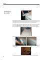
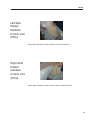
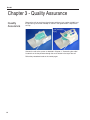
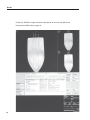
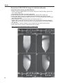
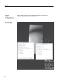
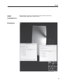
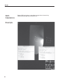
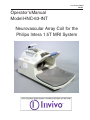
Part Number 500082
Rev 05
Operator's Manual
Model HNC-63-INT
Neurovascular Array Coil for the
Philips Intera 1.5T MRI System
1
Rev 05
February 2002
©2002 Invivo Corporation
All rights reserved. No part of this publication may be reproduced, transmitted, transcribed, stored in a retrieval
system, or translated into any language in any form by any means without the written permission of Invivo
Corporation.
Licenses and Trademarks
The Invivo Logo is a registered trademark of Invivo Corporation.
Intera is a registered trademark of Philips Medical Systems.
This manual describes the use and operation for the Invivo Neurovascular Array Coil on the Philips Intera
1.5T MRI Systems
Proper performance of this coil is guaranteed only while the coil is being used on the MR system (hardware/
software level) specified at the time of purchase. Upgrades or other modifications to the system software
and/or hardware may affect compatibility. Prior to upgrading your MR system, please contact the Invivo
Customer Service Department to discuss coil compatibility issues. Failure to do so may void your warranty.
Attention, Consult Accompanying
Documents
NOTICE:
Type BF Equipment
1. Ambient temperature range of -40°C to +70°C
THIS EQUIPMENT SHALL BE TRANSPORTED AND
STORED UNDER THE FOLLOWING CONDITIONS:
2. Relative humidity range of 10% TO 100%, including
condensation
Class II Equipment
3. Atmospheric pressure range of 500 hPa TO 1060 hPa
WARNING: This product contains chemicals, including
lead, known to the state of California to cause birth
defects or other reproductive harm. Wash hands after
handling.
Caution:
Federal law restricts this device to sale,
distribution, and use by or on the order
of a physician.
Invivo Corporation
3545 SW 47th Avenue
Gainesville, FL 32608
U.S.A.
2
Phone: (352) 336-0010
Fax: (352) 336-1410
[email protected]
www.invivocorp.com
Rev 05
Introduction
This manual describes the safety precautions, features, use and care, of the Invivo
HNC-63-INT Neurovascular Array Coil, compatible with the Philips Intera 1.5T MRI
System. Please review this manual thoroughly before using the device.
If you have any questions or comments on this manual, or need any assistance with the
use of the product, please contact your Invivo sales representative:
1-800-524-1476
Compatibility
The Invivo HNC-63-INT Neurovascular Array Coil is compatible with Philips Intera
1.5T MRI systems operating with Release 8.1.1 software or above.
NOTE: Release 8.1.1 software requires a SYNERGY MULTICONNECT patch
available through Philips Medical Systems. Contact your Philips
Representative for this software patch. Software releases after 8.1.1 do not
require the software patch.
A SYNERGY MULTICONNECT device is required for use of this product.
Contact your Philips Representative for the Synergy MultiConnect device.
Manufacturer:
Invivo Corporation
3545 SW 47th Avenue
Gainesville, FL 32608
U.S.A.
Phone:
Fax:
Web:
E-mail:
(352) 336-0010
(352) 336-1410
www.invivocorp.com
[email protected]
For Sales and Service
in Europe:
Invivo Germany GmbH
Schweinfurter Strasse 28
97076, Würzburg
Germany
Phone: +49 (0)931 359 76-0
Fax:
+49 (0)931 359 76-10
Authorized Representative in Europe:
GBM Authorised Representative Ltd.
The White House, 2 Meadrow
Godalming, Surrey GU7 3HN
United Kingdom
Phone:
Fax:
Web:
E-mail:
44 (0) 7710 039721
44 1483 424 310
www.mba-gbm.com
[email protected]
3
Rev 05
HNC Neurovascular Array Coil
Your HNC-63-INT Neurovascular Array Coil package consists of the following parts. Please inspect the package
upon receipt to make sure all parts are present and in good order. Use this guide to refer to part names thoughout
this manual.
Anterior Coil
Housing
(GRASP HERE)
Viewing
Mirrors
Anterior Coil
Housing
Anterior Coil Apron
(GRASP HERE)
Posterior
Coil Housing
Patient
Window
Latch
Patient
Comfort
Pad
The HNC-63-INT consists of two housings to facilitate lifting and positioning the coil on the patient cradle
and patient imaging. A latch is located on each side of the housing to secure the housings together and
ensure proper electrical connections between anterior and posterior housings. With latches in the open
position, the anterior housing may be lifted from the posterior housing.
Extreme care should be taken if attempting to move the HNC in one operation. When lifting the anterior housing
from the posterior housing, always grasp the coil by the apron and superior end. IMPORTANT: Never lift the
coil by the rungs in the patient viewing window or by the viewing mirror.
4
Rev 05
Table of Contents
HNC-63-INT Neurovascular Array Coil ........................................................ 4
Chapter 1 - Patient Safety ............................................................................ 6
Training ........................................................................................................ 6
Quality Assurance ....................................................................................... 6
Indications .................................................................................................... 6
Contraindications ......................................................................................... 6
Precautions .................................................................................................. 6
Cautions ....................................................................................................... 7
Emergency Procedures ............................................................................... 7
Technical Considerations ............................................................................ 8
Chapter 2 - Using the HNC-63-INT Neurovascular Array Coil ................... 9
Positioning the HNC-63-INT Coil on the Patient Table ................................ 9
Positioning the Patient ............................................................................... 10
Synergy MultiConnect (SMC) .................................................................... 11
Connecting the Cable ................................................................................. 12
Left Side Patient Interface Control Unit (PICU) ......................................... 13
Right Side Patient Interface Control Unit (PICU) ....................................... 13
Chapter 3 - Quality Assurance ................................................................... 14
Quality Assurance ..................................................................................... 14
SNR Calculations ....................................................................................... 19
Chapter 4 - Scanning Set Up ..................................................................... 23
Head and Neck Imaging ............................................................................. 23
Selecting the Active Coil ............................................................................ 23
Field of View and Coverage ....................................................................... 23
Survey Image ............................................................................................. 23
Using Autoshim .......................................................................................... 23
Scanning Step by Step .............................................................................. 24
Chapter 5 - Scan Protocols ........................................................................ 25
Chapter 6 - Maintenance ............................................................................. 26
Cleaning ..................................................................................................... 26
Storage ...................................................................................................... 26
5
Rev 05
Chapter 1 - Patient Safety
Training
This manual contains detailed information on the setup, positioning and use of the
Invivo Corporation coil.
Read the insructions carefully and thoroughly before
attempting to scan patients with the coil.
Quality
Assurance
The procedure described in the Quality Assurance Section of this manual should be
performed upon receipt of the coil to establish a baseline of coil performance. The
procedure should be repeated at regular intervals.
Indications
The coil is indicated for use, on the order of a physician, in conjunction with an MR
scanner as an accessory to produce images of the brain, cervical spine, anterior
neck, and vasculature of the head and neck, to the aortic arch.
Contraindications
The operator should be aware of the following contraindications for use related to the
strong magnetic field of the MR system:
Scanning is contraindicated for patients who have electrically, magnetically or
mechanically activated implants (for example. cardiac pacemakers). The
magnetic and electromagnetic fields produced by the MR System and coil may
interfere with the operations of these devices.
Scanning patients with intracranial aneurysm clips is contraindicated.
Precautions
Precautions should be taken when scanning patients with the following conditions:
Greater than normal potential for cardiac arrest
Increased likelihood for developing seizures or claustrophobia
Unconscious, heavily sedated, or confused physical or mental state
Inability to maintain reliable communications
Cautions
The following general warning statements apply to scanning with a magnetic
resonance system. For further details, review the warnings in your MR system
Operators Manual.
Do not cross or loop cables. Arcing and patient burns could result. Route
cables out of the magnet so that they do not touch the patient.
6
Rev 05
Assure that the patient is not touching the bore. If necessary, place pads
between the patient and the surface of the bore.
If the patient complains of warming, tingling, stinging, or similar sensations,
promptly stop the scan procedure, examine the patient, and contact the
responsible physician before continuing the procedure. Pay special
attention to very young, sedated, or other compromised patients who may
not be able to communicate effectively.
Patients with ferromagnetic metal should not be scanned because the
magnetic field may interact with implanted surgical clips or other ferromagnetic
materials.
Persons with cardiac pacemakers or other implanted electronic devices
should not enter the magnetic field zone delineated by the MR system
manufacturer.
There is a risk to scanning feverish or decompensated cardiac patients.
Facial makeup should be removed before scanning because it may contain
metal flakes which can cause skin and eye irritation. Permanent eyeliner
tattoos may cause eye irritation due to ferromagnetic particles.
Patients who work in environments in which there is a risk of having
embedded metallic fragments in or near the eye should be carefully
screened before undergoing an MR exam.
Visually inspect the cable insulator
jackets, strain reliefs and connector
boxes before each use. If the insulation
is broken, or if the cable is frayed,
immediately discontinue use of the
device.
Emergency
Procedures
In the unlikely event that a coil creates smoke, sparks, or makes an unusually loud
noise, or if the patient requires emergency assistance:
• Stop the scan if one is in progress.
• Remove the patient from the scan room if medical treatment is needed.
7
Rev 05
Technical
Considerations
The coil and accessories require special conditions regarding
electromagnetic compatibility. The coil must be installed and used in a
shielded scan room provided with the MR magnet and system. The user
must ensure that the scan room door is closed during system use. Failure
to do so may cause reciprocal interference with portable and mobile RF
communications equipment, affecting the performance of the MR coil and/
or such equipment.
The coil should only be used with the accessories specified in the operator’s
manual.
The use of accessories other than those specified in the operator’s manual
may result in decreased ESD immunity of the coil or MR system, causing
damage to the coil and/or system.
The equipment should not be used with other coils or equipment present in
the MR scanner except as specified in the Operator’s Manual.
Tampering with the cable pins and connector may damage the connector
and affect coil or system performance. Please verify that connector and
pins are not damaged before use.
8
Rev 05
Chapter 2 - Using the HNC-63-INT
Array Coil
Positioning the
HNC-63-INT
Coil on the
Patient Table
IMPORTANT: You must have the Synergy MultiConnect (SMC)
device and Level 8.1.1 or higher software in order for the Intera
system to recognize the coil. Additionally, Release 8.1.1 software
requires a Synergy MultiConnect patch to enable this coil to be
recognized by your system. Software releases above 8.1.1 do not
require the patch.
The HNC-63-INT Neurovascular Array Coil is designed for imaging of the brain,
cervical spine, anterior neck and vasculature in the head & neck, to the aortic arch.
Polarity (i.e., coil orientation) must be maintained to produce acceptable images. The
coil must be placed on the patient support with the cable exiting the coil on the right, as
you are facing the magnet.The HNC-63-INT coil is designed for head first exams
only!
The HNC coil is designed to rest directly on the patient support. With the anterior coil
housing removed, center the posterior coil housing on the patient support at the magnet
end of the patient support. Position support pad flush with the end of the HNC Coil.
The internal coil pad should be centered on the posterior housing. The pad serves to
provide additional patient comfort during the scan, and helps center the patient in the
coil, and is recommended for optimal coil performance.
9
Rev 05
Positioning
the Patient.
When lifting the anterior coil housing, always grasp the coil by the apron and the superior
end of the housing. Never lift the coil housing by the viewing window or mirror.
Adjust the patient so their shoulders are snug against the curved arch of the posterior
coil housing.
Firmly hold the anterior coil housing and carefully place it on the posterior coil housing.
As you lower the anterior coil housing, center and seat the RF connector pins while the
flat mating surfaces meet. Secure the latches on each side of the housing.
Slide the viewing mirror if necessary for patient viewing. Use the window on the
anterior coil housing to ensure the patient is centered properly. Using posititoning
beams, center on the anatomy to be imaged.
10
Rev 05
Synergy
MultiConnect
(SMC)
The Synergy MultiConnect (SMC) shown here is a
required option to use the HNC-63-INT coil.
IMPORTANT: You must have the SMC device
and Level 8.1.1 or higher software on your
Intera system.
Additionally, Release 8.1.1 software requires a
Synergy MultiConnect patch to enable this coil
to be recognized by your system. Contact your
Philips representative to receive this software
patch. Software releases above 8.1.1 do not
require the patch.
For more information on Synergy MultiConnect, please refer to Intera Release 8
Philips Application Guide/Volume 1 - Basics, Section 3.22.
The Synergy MultiConnect (SMC) is shown here with the HNC coil connector.
11
Rev 05
Connecting
the Cable
Attach the Synergy MultiConnect (SMC) holder to the same side of the support as the
patient ineterface control unit (PICU) facing the magnet. In this example, the PICU is on
the left side. Slide the holder toward the bore, even with the patients knees.
For systems with PICU on left side of magnet, transfer SMC connector across table
to the PICU. IMPORTANT: For SMC cable to reach PICU on left side of magnet,
patient will need to be in position within the magnet, e.g., coil at magnet isocenter.
Route the coil cable and connector to the SMC holder, as shown above.
Join the SMC and HNC connectors, and place the assembly into the SMC holder, as
shown above.
Landmark on the anatomy to be imaged and perform TRAVEL-TO-SCANPLANE.
12
Rev 05
Left Side
Patient
Interface
Control Unit
(PICU)
Attach SMC connector to PICU. Example above is left side PICU.
Right Side
Patient
Interface
Control Unit
(PICU)
Attach SMC connector to PICU. Example above is right side PICU.
13
Rev 05
Chapter 3 - Quality Assurance
Quality
Assurance
Remove the coil top and place the phantom positioner (part number 102485) and
the phantom (part number 102690) as shown in the figures below. Replace the
coil top.
Connect the coil to the system as detailed in Chapter 2, "Connecting the cable."
Landmark on the the phantom through the small window in the top of the coil.
Follow the proceedure found on the next 8 pages.
14
Rev 05
Run a SURVEY scan using the parameters listed below.
TIP: Save this SURVEY scan for future QA scans.
An example of the SURVEY images is on page 15.
Geometry
Coil Selection
-channel Combination
-connection
Multi Coil
Homogeneity correction
FOV(mm)
RFOV(%)
Foldover suppression
Matrix scan
-reconstruction
Scan percentage (%)
Stacks
-current
-type
-slices
-slice thickness (mm)
-slice gap
- - gap (mm)
-slice orientation
-foldover direction
Slice scan order
Stack display order
PlanAlign
RESTslabs
Patient position
-orientation
3IB-MRIDevic
2345
d
no
none
400.00
100.00
no
256
256
50.00
3
A
parallel
3
10.00
user defined
10.00
sagittal
AP
default
no
no
0
head first
supine
Contrast
Scanmode
M2D
-technique
FFE
Contrast enhancement T1
Fast Imaging mode
TFE
-shot mode
multi-shot
TFE factor
42
-shot interval
shortest
-profile order
linear
Echoes
1
-partial echo
no
TE
shortest
Flip angle (deg)
20.00
TR
user defined
-(ms)
15.00
Half Scan
no
Water fat shift
maximum
Shim
no
SPIR
TFE prepulse
-slice selection
-delay
MTC
SARmode
Gradient mode
no
invert
no
shortest
no
default
regular
Motion
Cardiac synchronisation
Respiratory compensation
Flow compensation
NSA
no
no
no
1
Dyn/ang
Angio
Quantitative flow
Manual start
Dynamic study
no
no
no
no
Postproc
Preparation phases
MIP/MPR
Images:
Autoview image
Reference tissue
Preset window contrast
Reconstruction mode
Save raw data
Push to workstation
Hardcopy protocol
Ringing filter
Silent mode
auto
no
O:M no no no
M
White matter
soft
immediate
no
no
no
no
no
Offc/ang
Stacks
-current
Stack Offc.AP (P=+mm)
RL (L=+mm)
FH (H=+mm)
Ang. AP (deg)
RL (deg)
FH (deg)
no
3
A
-20.00
0.00
0.00
0.00
-0.00
-0.00
15
Rev 05
Example of SURVEY images are below; note position of slices for the SNR check.
Proceed to the SNR check on page 16.
16
Rev 05
Run an SNR CHECK scan using the parameters listed below.
TIP: Save this SNR CHECK scan for future QA scans.
Position slices for the SNR CHECK as shown on page 15.
***IMPORTANT: Be certain to SAVE RAW DATA under Post Processing.***
Geometry
Coil Selection
-channel Combination
-connection
Homogeneity correction
FOV(mm)
RFOV(%)
Foldover suppression
Matrix scan
-reconstruction
Scan percentage (%)
Stacks
-type
-slices
-slice thickness (mm)
-slice gap
- - gap (mm)
-slice orientation
-foldover direction
Slice scan order
PlanAlign
RESTslabs
Patient position
-orientation
3IB-MRIDevic
2345
d
none
400.00
100.00
no
256
256
100.00
1
parallel
3
5.00
user defined
18.00
sagittal
AP
default
no
0
head first
supine
Contrast
Scanmode
-technique
Contrast enhancement
Fast Imaging mode
Echoes
-partial echo
TE
-(ms)
Flip angle (deg)
TR
-(ms)
Half Scan
Water fat shift
-(pixels)
Shim
MS
FFE
no
none
1
yes
user defined
15.00
30.00
user defined
200.00
no
user defined
2.000
no
SPIR
MTC
SAR mode
Gradient mode
no
no
default
regular
Motion
Cardiac synchronisation
Respiratory compensation
Flow compensation
NSA
SMART
no
yes
2
no
Dyn/ang
Angio
Quantitative flow
Manual start
Dynamic study
no
no
no
no
Postproc
Preparation phases
MIP/MPR
Images:
Autoview image
Reference tissue
Preset window contrast
Reconstruction mode
full
no
O:M no no no
M
Grey matter
soft
immediate
***Save raw data***
yes
Push to workstation
Hardcopy protocol
Ringing filter
Silent mode
no
no
no
no
Offc/ang
Stacks
Stack Offc.AP (P=+mm)
RL (L=+mm)
FH (H=+mm)
Ang. AP (deg)
RL (deg)
FH (deg)
no
1
-20.00
0.00
0.00
0.00
-0.00
-0.00
17
Rev 05
Reconstruct SNR CHECK image for individual channels
using the instructions provided below.
1. Before running the SNR CHECK scan, be sure to have the "Save Raw Data" option set to
"Yes" under [Postproc].
2. Do not delete the current scan from the [Scanlist].
3. Under the [Scanlist] icon, select the [Add Rec] icon, then the [Del. Recon] icon.
4. Left-mouse select on the scan to perform the reconstructions, then select [Proceed].
5. Change the "Synergy selection" option from "0" to "2" for reconstruction of the 2nd channel,
then select [Proceed].
6. Select [Options], and change the name of the reconstruction to "2".
7. Repeat steps 3-6 for each channel (channels 3,4,5), and change the "Synergy selection"
option to the next channel, then rename the scans appropriately for each channel selected
(i.e. 2,3,4,5)
8. From the [Scan List] icon, delete all scans except those renamed for each element.
9. Select [Start Scan] to start the reconstruction of the images.
Note: Example of reconstructed images are shown below.
18
Rev 05
SNR
Calulations
1.Select the reconstructed image from Channel 2, and display an eliptical ROI
with a total pixel area of 1300 mm squared. Refer to Philips Gyroscan Intera
Instructions Manual for ROI help.
2. Position ROI in the center of the phantom bottle, as shown below.
3. Bring up the Statistics for ROI, right-mouse select over the ROI number
(arbitrary number next to the ROI), left-mouse select on Statistics from the dropdown box, and select Statistics again from drop box.
4. Record the Signal Mean value.
5. Move ROI to background noise as shown below.
6. Record the noise standard deviation.
7. Divide the signal mean by the noise standard deviation.
8. Record this SNR value for future reference.
9. Spec > 50.
Example
19
Rev 05
SNR
Calulations
Example
20
Repeat SNR calculations as described on page 18 for the remaining
reconstructed images from channels 3,4,5.
Rev 05
SNR
Calulations
Repeat SNR calculations as described on page 18 for the remaining
reconstructed images from channels 3,4,5.
Example
21
Rev 05
SNR
Calulations
Example
22
Repeat SNR calculations as described on page 18 for the remaining
reconstructed images from channels 3,4,5.
Rev 05
Chapter 4 - Scanning Set Up
Head and Neck
Imaging
One of the advantages of using the Invivo HNC-63-INT Neurovascular
Array Coil (HNC) is the ability to acquire sequences of the head and
neck without having to re-enter the scan room to change coils and/or recenter the patient. When positioning a patient for a study of the brain as
well as an MRA of the carotids, center on the head as you would
normally do for a routine brain scan. Then, to acquire a coronal or
sagittal SURVEY image for the carotid MRA prescription, use an inferior
offset of “FH-120” and a 240 mm FOV.
Selecting the
Active Coil
The neurovascular array coil contains both a head coil and a neck coil. The head
coil (channel 2), neck coil (channels 3,4,5) or both head and neck coils
(channels 2,3,4,5) can be active at any given time. To select the active coil(s),
pick the proper channel(s) from the channel combination (ch. combination)
menu on your Intera Operator's Console.
EXAMPLES:
HEAD only: Select
Ch. combination 2
NECK only: Select
Ch. combination 3,4,5
HEAD & NECK: Select
Ch. combination 2,3,4,5
Field of View and
Coverage
For head or neck studies a FOV of 200 mm. is suggested, depending upon
head size. The HNC-63-INT coil is 280 mm. in diameter. If the entire coil is
active, a field of view of 320 mm. to 400 mm. is suggested. You may use
a smaller FOV if desired. Fold-over suppression must be set to YES.
Survey Image
The Intera body coil may be used at any time while the HNC-63-INT
Neurovascular Array Coil is in the scanner. This allows a large FOV (400
mm) body coil SURVEY to be performed, which is helpful in determining
the foot-head offset required for imaging the neck.
IMPORTANT!
Using Autoshim
AUTOSHIM is a feature of Intera software to improve image quality by
improving the magnetic field homogeneity within the FOV selected. The
improvement in image quality is often dramatic when the selected FOV is
far off center, and when acquiring SPIR images.
23
Rev 05
Scanning
Step by Step
Scan Select: Software Release 8.1.1, Choose "3IB-MRIDEVIC", Software Releases
above 8.1.1, choose "SMC-MRI".
Select Channel combination(s):
HEAD only: Select
Ch. combination 2
NECK only: Select
Ch. combination 3,4,5
HEAD & NECK: Select
Ch. combination 2,3,4,5
Plan Slices
Confirm Planning
Geometry Page: Homogeneity Correction, Select "NONE"
Start Scan
IMPORTANT: Upon scan completion, you must change channel combination if imaging a
different region. System will default to last Channel combination when another scan is
Added.
24
Rev 05
Chapter 5 - Scan Protocols
Invivo Corporation recomends that you select imaging protocols that have been
established by your radiologists. Additional protocols can be found within your
Philips Application Guides.
25
Rev 05
Chapter 6 - Maintenance
Cleaning
The Neurovascular Array coil and patient comfort pads may be cleaned by wiping
with a cloth dampened with a solution of 30% isopropyl alcohol and 70% tap water.
Do not pour any cleaning solution directly on the coil! Let coil housing and
pads dry before use.
Storage
The coil should be stored in an air-conditioned scan room or equipment room.
26
Rev 05
27