1
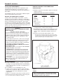
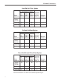
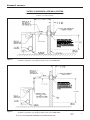
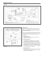
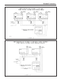
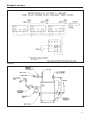
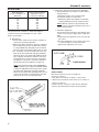
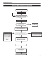
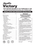
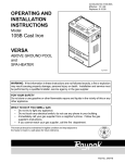
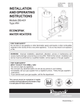
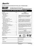
®
VICTORY II
™
This manual must be left with owner and
should be hung on or adjacent to the boiler
for reference.
HOT WATER MODELS VHS-30 THROUGH VHS-180
GAS-FIRED CAST-IRON BOILERS FOR NATURAL AND L.P. PROPANE GASES
Models with Intermittent Pilot System – Spark Ignition
INSTALLATION AND OPERATING INSTRUCTIONS
Contents . . . . . . . . . . . . . . . . . . . . . . . . . . . . . . . . . . . . . .Page
Dimensions, Rating and Orifice Sizes . . . . . . . . . . . . . . . . . . .2
Installation Requirements:
Boiler Location and Foundation . . . . . . . . . . . . . . . . . . . . .3
Minimum Clearances . . . . . . . . . . . . . . . . . . . . . . . . . . . . .3
Boiler Room Air Supply and Ventilation . . . . . . . . . . . . . . .4
Flue Gas Venting Requirements . . . . . . . . . . . . . . . . . . . . . . .4
Category II and III Venting:
Venting Material . . . . . . . . . . . . . . . . . . . . . . . . . . . . . . . . .5
Flue Length Restriction . . . . . . . . . . . . . . . . . . . . . . . . . . .5
Installation . . . . . . . . . . . . . . . . . . . . . . . . . . . . . . . . . . . . .5
Category I Venting:
Installation . . . . . . . . . . . . . . . . . . . . . . . . . . . . . . . . . . . .10
Vent Connector Material . . . . . . . . . . . . . . . . . . . . . . . . . .10
Venting Requirements . . . . . . . . . . . . . . . . . . . . . . . . . . .10
Venting System Regular Inspection . . . . . . . . . . . . . . . . . . . .14
Gas Piping . . . . . . . . . . . . . . . . . . . . . . . . . . . . . . . . . . . . . . .14
Electrical Wiring . . . . . . . . . . . . . . . . . . . . . . . . . . . . . . . . . . .14
Water Piping . . . . . . . . . . . . . . . . . . . . . . . . . . . . . . . . . . . . . .15
Piping a Heating-Cooling System . . . . . . . . . . . . . . . . . . . . .18
Operating Instructions:
Filling and Venting Water Systems . . . . . . . . . . . . . . . . . .18
Initial Start . . . . . . . . . . . . . . . . . . . . . . . . . . . . . . . . . . . .18
Safety Information . . . . . . . . . . . . . . . . . . . . . . . . . . . . . .19
Operating Instruction . . . . . . . . . . . . . . . . . . . . . . . . . . . .19
Burner Adjustment . . . . . . . . . . . . . . . . . . . . . . . . . . . . . .19
Safety Check . . . . . . . . . . . . . . . . . . . . . . . . . . . . . . . . . . . . .20
Care and Maintenance . . . . . . . . . . . . . . . . . . . . . . . . . . . . . .21
Sequence of Operations . . . . . . . . . . . . . . . . . . . . . . . . . . . .23
General Troubleshooting Guide . . . . . . . . . . . . . . . . . . . . . . .24
Appendix A and B . . . . . . . . . . . . . . . . . . . . . . . . . . . . . . . . .26
WARNING
The venting system of this boiler is under positive pressure when it is connected to the outdoors with 3" diameter
pipe. Leakage from this system can be hazardous and if
not avoided can result in death or serious injury. In addition to the recommendations within this manual and the
User’s Information Manual, the venting system, from the
blower to the outdoor discharge, must be carefully
checked annually by a qualified service agency.
IMPORTANT
READ ALL OF THE FOLLOWING
WARNINGS AND STATEMENTS
BEFORE READING THE
INSTALLATION INSTRUCTIONS
WARNING
LIQUEFIED PETROLEUM (L.P.)
PROPANE GAS-FIRED BOILERS
Installation location ONLY as permitted in paragraph
entitled "LIQUEFIED PETROLEUM (L.P.) PROPANE
GAS-FIRED BOILER LOCATION" on page 3 of this
instruction book.
The above warning does not apply to NATURAL gasfired boilers.
The installation must conform to the requirements of
the authority having jurisdiction or, in the absence of
such requirements, to the National Fuel Gas Code,
ANSI Z223.1-latest edition. The installation must also
conform to the additional requirements in this Slant/Fin
Instruction Book.
In addition where required by the authority having jurisdiction, the installation must conform to American
Society of Mechanical Engineers Safety Code for
Controls and Safety Devices for Automatically Fired
Boilers, No. CSD-1.
WARNING
This boiler, gas piping and accessories must be
installed, connected, serviced and repaired by a
trained, experienced service technician, familiar with all
precautions required for gas-fired equipment and
licensed or otherwise qualified, in compliance with the
authority having jurisdiction.
Heating Contractor
Boiler Model Number
Address
Boiler Serial Number
Phone Number
Installation Date
Publication No. VHS-40
Part No. 44-0831
Printed in U.S.A.404
VICTORY II
VHS Models
Figure 1. Views - Dimensions - Data
LEFT END VIEW
FRONT VIEW
RIGHT END VIEW
NOTE: Height dimensions increase by 13⁄4" and depth increases to 221⁄4" when combustible floor kit is used.
Boiler
Model
Input
Btuh
No. of
Sections
A
B
1
Approx.
Total Wt.
Full of
Water (lb.)
VHS-30
30,000
2
8 ⁄8"
145⁄8"
190
VHS-60
60,000
3
11 ⁄8"
175⁄8"
250
VHS-90
90,000
4
141⁄8"
205⁄8"
310
VHS-120 120,000
5
17 ⁄8"
23 ⁄8"
365
VHS-150 150,000
6
20 ⁄8"
26 ⁄8"
425
VHS-180 180,000
7
231⁄8"
295⁄8"
485
1
1
5
1
5
Figure 2. Base Assembly Victory II - VHS Boiler
Burners
Pilot
Burner
access door
Gas valve
Gas manifold
Gas
Type
Orifice
Size for
Sea Level
Orifice Sizes for High Altitudes
Includes 4% Reduction for Each 1000 Feet
2000
3000
4000
Elevation — Feet
5000 6000 7000
8000
9000
10000
Natural
#49
50
50
50
51
51
51
52
52
52
Propane
#57
58
59
59
60
60
61
62
63
63
Orifice sizes indicated for sea level above are factory installed in boiler unless otherwise specified
by the local authority. Orifice table is based on a higher heating value between 1000 Btuh and
1010 Btuh for Natural Gas (See page 19, if local higher heating value exceeds these numbers).
See page 19, for burner input adjustment.
2
VICTORY II
VHS Models
INSTALLATION REQUIREMENTS
The installation must conform to the requirements of the
authority having jurisdiction or, in the absence of such
requirements, to the National Fuel Gas Code, ANSI Z223.1latest edition.
This installation must also conform to the additional requirements in this Slant/Fin Instruction Book.
NATURAL GAS-FIRED BOILER LOCATION
Provide a level, solid foundation for the boiler. Location
should be as near as possible to chimney or outside wall so
that the flue pipe from boiler is short and direct. (See Appendix A for vent terminal location restrictions.) The location
should also be such that the gas ignition system components
are protected from water (dripping, spraying, rain, etc.) during
appliance operation and service (circulator replacement, condensate trap, control replacement, etc.).
WARNING
LIQUEFIED PETROLEUM (L.P.) PROPANE GAS-FIRED
BOILER LOCATION
REQUIRES SPECIAL ATTENTION
Liquefied Petroleum (L.P.) propane gas is heavier than air.
Therefore, propane boilers, piping, valves should NOT be
installed in locations where propane leaking from defective
equipment and piping will "pool" in a basement or other
space below the leak.
MINIMUM CLEARANCES FROM COMBUSTIBLE
CONSTRUCTIONS
A. Minimum clearances to the exterior surfaces of the boiler
shall be as follows:
MINIMUM ALCOVE AND CLOSET CLEARANCE
For Combustible
Surface
Construction
Front
6"
Rear
6"
Left Side
6"
Right Side
12"
Top
12"
Flue Connector:
Enclosed —
6"
Unenclosed —
2"
Recommended
for Service
18"
18"
18"
24"
12"
6"
6"
B. Provide accessibility clearance of 24" on sides requiring
servicing and 18" on sides used for passage.
C. All minimum clearances shown above must be met. This
may result in increased values of some minimum clearances in order to maintain the minimum clearances of
others.
D. Clearance from hot water pipes shall be 1 inch**.
** At points where hot water pipes emerge from a floor, wall or ceiling,
the clearance at the opening through the finished floor boards or wall
or ceiling boards may be not less than 1/2 inch. Each such opening
shall be covered with a plate of uncombustible material.
A spark or flame from the boiler or other source may ignite
the accumulated propane gas causing an explosion or fire.
Provide a level, solid foundation for the boiler. Location
should be as near the chimney as possible so that the flue
pipe from boiler to chimney is short and direct.
The UNIFORM MECHANICAL CODE may be in effect in
your geographic area.
The following precautions are cited by the 1994 UNIFORM
MECHANICAL CODE, section 304.6:
"LPG Appliances. Liquefied petroleum gas-burning
appliances shall not be installed in a pit, basement or
similar location where heavier-than-air-gas might collect.
Appliances so fueled shall not be installed in an abovegrade under-floor space or basement unless such location is provided with an approved means for removal of
unburned gas."
Consult Chapter 5 of the 1994 UNIFORM MECHANICAL
CODE for design criteria of the "approved" means for
removal of unburned gas.
BOILER FOUNDATION
A. Provide a solid, level foundation, capable of supporting
the weight of the boiler filled with water, and extending at
least 2" past the jacket on all sides. See dimensions of
boilers, page 2.
B. For installation on non-combustible floors only*.
C. If boiler is to be located over buried conduit containing
electric wires or telephone cables, consult local codes or
the National Board of Fire Underwriters for specific
requirements.
* Installation on combustible flooring allowed only with proper Combustible Floor Kit. Kit part number is printed on boiler rating plate.
In no case may the boiler be installed on carpeting.
Figure 3.
SAFETY
KEEP THE BOILER AREA CLEAR AND FREE FROM
COMBUSTIBLE MATERIALS, GASOLINE AND OTHER
FLAMMABLE VAPORS AND LIQUIDS.
3
VICTORY II
BOILER ROOM AIR SUPPLY AND VENTILATION
An ample supply of air is required for combustion and ventilation. When buildings are insulated, caulked and weatherstripped, now or later on, direct openings to outside may be
required and should be provided. If the boiler is not near an
outside wall, air may be ducted to it from outside wall openings.
Provisions for combustion and ventilation air must be made
in accordance with section 5.3, Air for Combustion and Ventilation, of the National Fuel Gas Code, ANSI Z223.1-latest
edition, or applicable provisions of the local building codes.
The following recommendation applies to buildings of energy-saving construction, fully caulked and weatherstripped.
INSTALLATION IN ENCLOSED BOILER ROOM REQUIRES
TWO UNOBSTRUCTED OPENINGS FOR PASSAGE OF
AIR INTO THE BOILER ROOM:
1. Air drawn horizontally from outdoors DIRECTLY
through an outside wall; one louvered opening near
the floor and one louvered opening near the ceiling, each
opening with a minimum FREE air passage area of 1
square inch per 4000 Btuh of total appliances’ input.
2. Air drawn horizontally through HORIZONTAL
DUCTS; one opening near the floor and one opening
near the ceiling, each opening with a minimum FREE air
passage area of 1 square inch per 2000 Btuh of total
appliances’ input.
3. Air drawn VERTICALLY from outdoors; one opening at
the floor and one opening at the ceiling, each opening
with a minimum FREE air passage area of 1 square
inch per 4000 Btuh of total appliances’ input.
4. Air drawn from inside the building; one opening near
the floor and one opening near the ceiling, each opening
with a minimum FREE air passage area of 1 square
inch per 1000 Btuh of total appliances’ input.
IF BOILERS ARE INSTALLED ADJACENT TO OTHER
FUEL BURNING EQUIPMENT, THE AREA OF FREE
OPENINGS MUST BE APPROPRIATELY INCREASED TO
ACCOMMODATE THE ADDITIONAL LOAD.
Openings must never be reduced or closed. If doors or windows are used for air supply, they must be locked open. Protect against closure of openings by snow and debris. Inspect
frequently.
No mechanical draft exhaust or supply fans are to be used in
or near the boiler area.
The flow of combustion and ventilating air to the boiler must
not be obstructed.
4
VHS Models
FLUE GAS VENTING REQUIREMENTS
The Victory II series boiler is a high efficiency, mechanically
induced draft boiler and, therefore, requires different venting
arrangements than natural draft, lower efficiency boilers.
THE FOLLOWING INSTRUCTIONS MUST BE CAREFULLY
READ AND FOLLOWED IN ORDER TO AVOID ANY HAZARDOUS CONDITIONS DUE TO IMPROPER INSTALLATION OF THE FLUE GAS VENTING SYSTEM.
The vent piping installation MUST be in accordance with
these instructions and with ANSI Z223.1-latest edition
NATIONAL FUEL GAS CODE, Part 7, Venting of Equipment.
Other local codes may also apply and must be followed.
Where there is a conflict between these requirements, the
more stringent case shall apply.
The use of a vent damper is NOT permitted on this boiler
series.
Approved Venting Applications
Victory II model VHS-90 through 180 are Category III and
VHS-30 and 60 are Category II boilers, these boilers must
be vented by proper 3" diameter venting system (see Category II and III venting - page 5).
Models VHS-90 through 180 are also Category I boilers
when using a minimum of 5" diameter connector and vented
into a natural draft chimney or Type “B” vent using a 3"x5"
diameter vent adapter (see Category I venting - page 10).
VICTORY II
VHS Models
2. Flue Length Restriction
Maximum and minimum equivalent flue length for different
systems are given in the tables on page 6. Equivalent flue
length is sum of straight flue lengths and equivalent
length of elbows. The vent termination is in addition to the
allowed equivalent lengths.
Example: Boiler Model VHS-180 is to be installed at sea
level with 2 elbows using Heat-Fab vent system. Maximum
straight run would be: 40 - 2 x 3 = 34ft. If same boiler is to
be installed in Colorado Springs (5,980 ft. altitude), the maximum straight run would be: 20 - 2 x 3 = 14 ft.
3. Installation
A. Horizontal Venting:
Figures 5 and 6 show typical horizontal venting. For
combustible wall passage of vent piping a U.L. listed
thimble must be used. See Figures 5 and 6 for wall
thimble Part Numbers and more information.
Figure 4. Vent Sealing Instructions
(Consult vent manufacturer’s instructions.)
CATEGORY II AND III VENTING
1. Vent Material
A) The vent system for horizontal or vertical venting
(Category II and III) must be UL listed single wall 3"
diameter AL29-4Cs stainless steel material. The following manufacturers’ systems are approved for use within
a specified minimum and maximum equivalent vent
length for each model. Proper adapter must be used as
a connector between Victory II boilers flue collar and
venting system as shown below:
Manufacturer Type/System Adapter Part
No.
Sealant
Heat-Fab. Inc.
Saf-T Vent
Not Required
RTV 106 or Dow
Corning 732
Heat-Fab. Inc.
Saf-T Vent
EZ Seal
Not Required
Not Required
ProTech System,
Inc.
FasNSeal
FSA-SLB-3
Not Required
Flex-L
International, Inc.
StaR-34
SRASFA3
GE-1S806
Z-Flex, Inc.
Z-Vent
O2SVSSLA2
GE, RTV 106
Heat-Fab Part Numbers for various items of vent system are
listed in Slant/Fin Part List, Publication No. VHS-10PL.
B) When joining the various components of the above
listed vent systems, the manufacturers’ instructions
should be closely followed to insure proper sealing.
C) Use sealant specified by vent system manufacturer
for sealing of pipe and fittings. See Figure 4 for
proper application of vent pipe sealing for Safe-T vent
system by Heat-Fab. Inc.
D) All vent connections must be liquid and pressure tight
E) Flue vent system CANNOT be cut to length. Consult
manufacturer’s instructions. For Heat-Fab system, use
slip joint connector to adjust pipe lengths dimensions.
F) DO NOT use plastic or galvanized flue pipe.
B. Vertical Venting:
Figure 7 shows typical vertical venting. A fire stop is
required for each ceiling and floor penetration. An
existing chimney (see Figure 8) may be used as a
chase for vertical venting. Other appliances CANNOT
be vented into the same chimney or vent pipe within
the chimney.
For both, horizontal and vertical venting, the following
points MUST be followed:
A. All Victory II boilers are equipped with a built-in condensation drain and trap. The trap loop must be filled
with water. DO NOT operate the boiler without filling
the trap with water to prevent flue gas discharge into
space. The drain should extend to a floor drain or to a
container which may require emptying periodically.
B. The horizontal vent pipe must be sloped upward from
the boiler at a pitch of at least 1/4" per 1 foot of run, so
that the condensate from the vent system runs to the
drain trap.
C. The horizontal vent pipes must be supported with pipe
straps at intervals no greater than indicated by vent
pipe manufacturer’s instructions. The vertical portion
vent pipe also must be supported per manufacturer’s
instructions.
D. Minimum clearances of vent pipes from combustible
constructions must be maintained (see Page 3).
E. Common venting with other appliances or another Victory II boiler is NOT allowed.
F. The vent piping must terminate with a screened elbow
or tee. See Figures 5 and 6 for horizontal and 7 and 8
for vertical termination information. A cap termination
may be used for vertical venting.
G. See Appendix A for vent system location and condensation drain requirements.
H. For roof passage of vent piping a U.L. listed roof flashing must be used.
s: AL 29-4C is a registered trademark of Allegheny Ludlum Corp.
5
VICTORY II
Heat-Fab Saf-T Vent System
Max. Equivalent Length (Ft.)
Boiler
Model No.
0 to
5500 Ft.
Altitudes
Equivalent
5500 to 7000 to
Length of
7000 Ft. 10,000 Ft. each 90°
Altitudes Altitudes Elbow, Ft.
Minimum
Length, Ft.
VHS-30,
60, 90
and 120
40
40
40
3
2
VHS-150
40
40
20
3
2
VHS-180
40
20
20
3
2
ProTech FasNSeal System
Max. Equivalent Length (Ft.)
Boiler
Model No.
0 to
5500 Ft.
Altitudes
Equivalent
Length of
5500 to 7000 to
7000 Ft. 10,000 Ft. each 90°
Elbow, Ft.
Altitudes Altitudes
Minimum
Length, Ft.
VHS-30,
60, 90
and 120
30
30
30
6
2
VHS-150
30
30
15
6
2
VHS-180
30
15
15
6
2
Flex-L StaR-34 and Z-Flex Z-Vent System
Max. Equivalent Length (Ft.)
Boiler
Model No.
0 to
5500 Ft.
Altitudes
Equivalent
5500 to 7000 to
Length of
7000 Ft. 10,000 Ft. each 90°
Altitudes Altitudes Elbow, Ft.
Minimum
Length, Ft.
VHS-30,
60, 90
and 120
35
35
35
6
2
VHS-150
35
35
18
6
2
VHS-180
35
18
18
6
2
Note: Vent termination is in addition to the allowed equivalent length.
6
VHS Models
VICTORY II
VHS Models
VICTORY II HORIZONTAL (SIDEWALL) VENTING
All joints must be liquid and pressure tight. Use U/L listed single wall 3" dia.
AL29-4C* S.S. venting materials
Figure 5
* Definition of Snow Line: Knowledge of local conditions will reveal the maximum height that repeated
snowfalls accumulate to. The height should be used as the SNOW LINE.
Figure 6
* Definition of Snow Line: Knowledge of local conditions will reveal the maximum height that repeated
snowfalls accumulate to. The height should be used as the SNOW LINE.
*
: AL 29-4C IS A REGISTERED TRADEMARK OF ALLEGHENY LADLUM CORP.
44vh40-6
REV.A
7
VICTORY II
Figure 7.
8
VHS Models
VICTORY II
VHS Models
Figure 8.
9
VICTORY II
CATEGORY I VENTING (Natural Draft Chimney and
Type “B” Venting)
1. Installation
Model VHS-90, VHS-120, VHS-150 and VHS-180 may be
vented into a natural draft masonry chimney or natural
draft type“B” vent if a 3" diameter stainless steel elbow
connected to the boiler’s flue collar and the vent connector converted to 5" diameter using a 3" x 5" vent adapter.
Single or multiple appliance venting are shown in Figures
9 and 10.
2. Vent Connector Material
Vent connectors may be single wall or Type “B” made of
galvanized or stainless steel materials.
3. Venting Requirements
If the boiler vent is to be installed into a natural draft
masonry chimney or Type “B” venting, it must be in accordance with National Fuel Gas Code ANSI Z223.1-latest
edition, Part 7, Part 11 and Appendix G.
For a masonry vitreous tile-lined chimney which is not
exposed to the outdoors, use Table 1 in this Slant/Fin
manual for venting requirements. DO NOT install this system into an unlined masonry chimney.
If a masonry chimney is exposed to the outdoors on one
or more sides below the roof line (exposed chimney), it
must be re-lined with a UL listed metallic liner system.
See Table 2 in this Slant/Fin manual for venting requirements of metallic re-lined chimneys.
If a Type “B” vent system is used, it must NOT be exposed
to the outdoors below the roof line. See Table 2 in this
Slant/Fin manual for venting requirements. Vent connectors serving appliances vented by natural draft shall NOT
be connected into any portion of mechanical draft systems operating under positive pressure.
In some cases, the vent connector diameter must be upsized further to 6" or 7". Refer to Table 1 and 2 for installations requiring this increased size.
If this boiler is replacing a boiler which is connected to a
common venting system with other natural draft, gas-fired
appliances, the removal of the existing boiler from the venting system is likely to cause the system to be too large for
proper venting of the appliances remaining connected to it.
At the time of removal of the existing boiler, the test procedure specified in Appendix “B” must be followed.
10
VHS Models
VICTORY II
VHS Models
Natural Draft Chimney and Type “B” Venting Tables
Table 1. Masonry Vitreous Tile-Lined Chimney (not metal lined)
Chimneys not exposed to the outdoors below the roof line. (5" dia. vent adapter must be used)
Boiler
Model(s) †
VHS-90
VHS-120
VHS-150
VHS-180
VHS-180
Additional
Gas Appliance
in Venting System
No
No
VHS-90
VHS-120
VHS-150
VHS-180
Yes
VHS-150
VHS-180
Yes
Connector
Type “B”
Single-wall
Type “B”
Single-wall
1.
2.
3.
4.
1.
2.
3.
4.
Requirements*
Connector diameter must be upsized to 7".
Chimney height limits: Min. 15 ft., Max. 30 ft.
Lateral length restriction applies (Table 10-3)
Internal area of chimney: Min. 50 sq. in.,
Max. 269 sq. in.
Connector diameter must be upsized to 7".
Chimney height limits: Min. 15 ft., Max. 30 ft.
Max. lateral length may not exceed 2 ft.
Internal area of chimney: Min. 50 sq. in.,
Max. 269 sq. in.
1. See Table 10-8 for chimney height
and connector length restrictions.
2. Connector may have to be upsized to 6" diameter
to meet requirement of 10-8.
1. See Table 10-9 for chimney height
and connector length restrictions.
2. Connector may have to be upsized to 6" diameter
to meet requirement of 10-9.
National Fuel Gas Code
Reference Table No.*
(ANSI Z223.1)
10-3 (1999 edition)
10-4 (1999 edition)
10-8 (1999 edition)
10-9 (1999 edition)
Table 2. Type “B” Venting and Metal-Lined Masonry Chimney
UL LISTED MATERIALS ONLY. (5" dia. vent adapter must be used)
Boiler
Model(s) †
VHS-90
VHS-120
VHS-150
VHS-180
Additional
Gas Appliance
in Venting System
No
Connector
Type “B”
Requirements*
See Table 10-1 for minimum and maximum
of vent height and lateral length restriction.
National Fuel Gas Code
Reference Table No.*
(ANSI Z223.1)
10-1 (1999 edition)
VHS-90
VHS-120
VHS-150
VHS-180
No
VHS-90
VHS-120
VHS-150
VHS-180
Yes
VHS-120
VHS-150
VHS-180
Yes
Single-wall
See Table 10-2 for minimum and maximum
of vent height and lateral length restriction.
10-2 (1999 edition)
Type “B”
Single-wall
1. See Table 10-6 for vent height and
connector length restrictions.
2. Connector and vent diameter may have to be
increased to 6" or 7" to meet requirement of
Table 10-6.
10-6 (1999 edition)
1. See Table 10-7 for vent height and
connector length restrictions.
2. Connector and vent diameter may have to be
increased to 6" to meet requirement of
Table 10-7.
10-7 (1999 edition)
† Only Victory II boiler models shown for each application permitted to be installed in that manner specified.
• Also see Z223.1 –– 1999 Chapter 7 and 10.
11
VICTORY II
Figure 9.
12
VHS Models
VICTORY II
VHS Models
Figure 10.
13
VICTORY II
VENTING SYSTEM REGULAR INSPECTION
A. Inspect the system regularly for condensation, corrosion
and/or physical damage. A qualified professional should service the boiler annually and include such an inspection at that
time. The homeowner should look over the system monthly for
damage, water stains, any signs of rust, other corrosion or
separation of the flue (vent) tubing and fittings.
B. Should an inspection turn up signs of condensation, corrosion
or damage, the boiler should be shut down immediately and
the condition should be corrected by a qualified professional.
C. All Victory II boilers are equipped with a built-in condensation
drain and trap. The trap loop must be filled with water. DO NOT
operate the boiler without filling the trap with water to prevent
flue gas discharge into space. Periodic inspection should be
made of this assembly for deterioration of the tubing and to
insure that the trap is not plugged. If it is plugged or appears to
have excessive sediment in it, it should be removed from the
drain assembly, straightened out to clear the obstruction,
reformed, filled with water and reinstalled as before.
GAS PIPING
A. Local installation codes apply. The pipe joint compound used
on threads must be resistant to the action of liquefied petroleum gases.
B. The gas supply line to the boiler should be run directly from
the meter for natural gas or from the fuel tank for L.P.
propane gas. See page 2 for location of union and manual
main shut-off valve that may be specified locally.
Selecting pipe size for natural gas:
1. Measure or estimate the length of piping from the meter
to the installation site.
2. Consult gas supplier for heating value of gas (Btu/cu. ft.).
3. Divide boiler rated input by heating value to find gas flow
in piping (cu. ft. per hour).
4. Use table below to select proper pipe size.
Example: Boiler model VHS-150 is to be installed. Distance
from gas meter to the boilers is 30 ft. Heating value of natural
gas is 1020 Btu/cu. ft. Select proper pipe size.
Gas flow = 150,000 Btu/hour = 147 cu. ft. per hour
1020 Btu/cu. ft.
At 30 ft. length of pipe, match required capacity from table on
this page (choose higher capacity, in this case is 152 cu. ft. per
hour). Required pipe size is 3/4".
Improper gas pipe sizing will result in pilot flame outages, insufficient heat and other installation difficulties. For more information and also if other appliances are to be attached to the piping
system, see Appendix C of National Fuel Gas Code ANSI
Z223.1-latest edition.
C. The boiler and its gas connection must be leak tested before
placing the boiler in operation. Use liquid soap solution for all
gas leak testing. DO NOT use open flame. This boiler and its
individual shutoff valve must be disconnected from the gas
supply piping system during any pressure testing of that system at test pressures in excess of 1/2 PSIG. This boiler
must be isolated from the gas supply piping system by
closing its individual manual shutoff valve during any
14
VHS Models
Gas Flow In piping -- cu. ft. per hr.
Iron Pipe Size (IPS) — inches
Length
of pipe
in Feet
1/2
10
20
30
40
50
60
70
80
90
100
132
92
73
63
56
50
46
43
40
38
/4
1
11/4
11/2
278
190
152
130
115
105
96
90
84
79
520
350
285
245
215
195
180
170
160
150
1050
730
590
500
440
400
370
350
320
305
1600
1100
890
760
670
610
560
530
490
460
3
At pressure drop of 0.3 in. water, specific gravity = 0.6.
pressure testing of the gas supply piping system at test
pressures equal to or less than 1/2 PSIG.
D. All gas piping used should be inspected thoroughly for cleanliness before makeup. A sediment trap must be provided, as
illustrated on page 2.
E. The minimum and maximum gas supply pressure (at the
inlet of gas valve) are shown on the boiler rating plate for the
type of gas used. Gas supply pressure should never be less
than minimum or more than maximum pressure when the
boiler or any other appliance is turned on or off.
ELECTRICAL WIRING
DANGER: Before wiring, always turn off electric power
supply, otherwise, shock or death can result.
1. Power Supply
A separately fused circuit is recommended. Use a standard
15 Amp. fuse or breaker and 14 gage conductors in BX
cable or conduit.
Provide disconnect means and overload protection as
required. See boiler wiring diagram (Figure 11a) and ladder
diagram (Figure 11b).
Boiler must be electrically grounded in accordance with the
requirements of the authority having jurisdiction, or, in the
absence of such requirements, with the National Electrical
Code, ANSI/NFPA 70-latest edition.
2. Power Connection
A. Remove electrical junction box cover.
B. Hot connection lead is black. Neutral connection lead is white.
C. Connect ground wire to ground screw inside the junction box.
D. Replace junction box cover.
3. Thermostat Connections
Thermostat wire connections must be to T and TV screw terminals of Aquastat. See wiring diagram, Figure 11a.
4. Multi Zoning
For pump zoning system, see Figures 12 and 13, for zone
valve system, see Figure 14. DO NOT use boiler transformer
to power external accessories like zone valve and relays,
overload and/or burned-out transformer and boiler malfunction can result.
VICTORY II
VHS Models
Figure 11a.
WATER PIPING
Always follow good piping practices. Observe minimum 1"
clearance to combustibles around all uninsulated hot water
pipes or when openings around pipes are not protected by
non-combustible materials.
On a hot water boiler installed above radiation level, the boiler must be provided with a low water cutoff device at the time
of installation by the installer. (see Figure 15 for piping
arrangement)
1. Supply and Return
For tapping sizes see dimensions on page 2. Shut-off
valves are recommended.
2. Circulating Systems
Victory II boilers are equipped with a water circulating
pump mounted to the return water connection on the
boiler. This pump location is appropriate for most installations. It may be desired and proper to locate this pump to
the alternate pump location shown in Figure 15, especially
when applied to larger systems using high-head pumps.
Figure 11b.
When the pump is removed there is a 11/2" FPT tapping
that the return pipe may be attached to.
3. Air Control System
Diaphragm type compression tank is used to control system pressure. It must be installed at the boiler or between
boiler and supply main pump(s).
15
VICTORY II
16
VHS Models
VICTORY II
VHS Models
Figure 14.
Figure 15. Piping Arrangement
17
VICTORY II
An automatic air vent is used to remove air from the system. It should be installed in the top of the boiler as shown
in Figure 15. If system pressure needs further control, add
an additional tank in parallel with original tank or install a
larger capacity tank. Use appropriate size tank for volume
of water in system. See chart for boiler’s volume.
Model
Boiler Water Content
Pounds
Gallons
VHS-30
17.5
2.1
VHS-60
24.75
3.0
VHS-90
32.00
3.8
VHS-120
39.25
4.7
VHS-150
46.50
5.6
VHS-180
53.75
6.4
4. Cold Water Fill
Pressure reducing (fill) valve and shut-off valve should be
installed.
5. Relief Valve Discharge Piping
Use same size or larger piping than valve outlet. Must terminate 6" minimum from floor with a plain (no threads)
end. Place a bucket under pressure relief valve discharge.
Make sure discharge is always visible. DO NOT hard-pipe
to drain piping.
6. Providing Protection from Freezing
Anti-freeze is sometimes used in hydronic heating systems
to protect against freeze-up in the event of power failure or
control shutdown when the building is unoccupied. It
should be recognized that unless the building is kept
above freezing temperature by some means, the plumbing
system is not protected. Two types of anti-freeze may be
used: ETHYLENE GLYCOL, used in automobiles, has
desirable properties, but is toxic. Its use may be prohibited
when system water/glycol solution is in contact with a
potable water vessel (as an indirect hot water heater with
built-in heating coils). PROPYLENE GLYCOL is used in
the quick-freeze food industry; it is practically non-toxic. Its
use may be permitted when system solution is in contact
with a potable water vessel. When anti-freeze must be
used, inhibited propylene glycol is recommended. Useful
information on the characteristics, mixing proportions, etc.
of glycol in heating systems is given in Technical Topics
No. 2A, available from the Hydronics Institute, 34 Russo
Place, Berkeley Heights, NJ 07922. Consult glycol manufacturers for sources of propylene glycol.
7. Water Treatment
A good water treatment program will not only extend the
useful life of this boiler but it will also save much of the
time and expense of repairs made necessary by preventable occurrences. A reputable water treatment company should be consulted to evaluate and determine the best
overall treatment program for your boiler equipment.
PIPING A HEATING - COOLING SYSTEM TO A WATER
BOILER AND CHILLER
Figure 16 illustrates a method of piping a heating-cooling system to a water boiler and a chiller. Hand valves (shown) or
automatic valves must be installed to prevent circulation of
chilled water in the boiler or hot water in the chiller.
18
VHS Models
The air control system and pressure control system must
operate with chiller only, or the boiler only, being valved to the
piping system. Separate control devices on the boiler and
chiller may be used, or a single set of air and pressure controls on the common piping may be preferred.
If the boiler is used to supply hot water to heating coils in air
handling units, flow control valves or other devices must be
installed to prevent gravity circulation of water in the coils during the cooling cycle.
Figure 16.
OPERATING INSTRUCTIONS, BASIC
1. Filling and Venting Water Systems
A. Fill the system with water. Vent or purge of air.
B. Fire the boiler as soon as possible (see following warning and instructions) and bring water temperature in
the system.
C. Vent air and add water as needed to achieve operating
pressure on boiler gauge. Pressure must be between
approximately 12 psi (cold water) and 25 psi at water
temperature setting of high limit control, for boilers
equipped with 30 psi relief valves. Boilers rated for a
higher pressure and equipped with a matching relief
valve may operate at a higher pressure, but no higher
than 5 psi below the relief valve opening pressure.
D. Check for and repair any leaks before placing system
in service.
BEFORE FIRING BOILER, make these checks:
1. System is full of water. Air is vented or purged.
2. Relief valve is installed in accordance with ASME Boiler and Pressure Vessel Code, Section IV. Valve opening is not closed or reduced in size.
3. Venting is installed according to instructions under
“FLUE GAS VENTING REQUIREMENTS”.
4. All wiring is completed, following applicable wiring diagrams.
5. Using soap solution, check for gas leaks in all gas piping from meter to boiler pilot and manifold. DO NOT
use open flame.
2. Initial Start
Safe lighting and other performance criteria were met
when testing various gas manifold and control assemblies
used on the Victory II Series Boilers under the ANSI
Z21.13- latest edition.
VICTORY II
VHS Models
Instructions
Follow the lighting instructions in this manual. These instructions are also attached to the boiler.
SAFETY INFORMATION
For Your Safety Read Before Operating
WARNING: If you do not follow these instructions exactly,
a fire or explosion may result causing property damage,
personal injury or loss of life.
A. This appliance is equipped with an ignition device which
automatically lights the pilot. DO NOT try to light the pilot
by hand.
B. BEFORE OPERATING smell all around the appliance
area for gas. Be sure to smell next to the floor because
some gas is heavier than air and will settle on the floor.
WHAT TO DO IF YOU SMELL GAS:
• DO NOT try to light any appliance.
• DO NOT touch any electric switch: DO NOT use any
phone in your building.
• Immediately call you gas supplier from a neighbor’s
phone. Follow the gas supplier’s instructions.
• If you cannot reach your gas supplier, call the fire
department.
C. DO NOT use this appliance if any part has been underwater. Immediately call a qualified service technician to
inspect the appliance and to replace any part of the control
system and any gas control which has been underwater.
9. Set thermostat to desired setting.
10. If appliance will not operate, follow the instructions
“To Turn Off Gas To Appliance” and call your service or
gas supplier.
To Turn Off Gas to Appliance
1. Set thermostat to lowest setting.
2. Turn off all electric power to the appliance if service is to be
performed.
3. Turn gas control knob clockwise
to OFF.
DO NOT force.
3. Burner Adjustment
A. Adjust gas input rate:
1. Consult gas supplier for higher heating value* of gas
(Btu/cu. ft.).
2. Set thermostat high enough so that boiler will remain
on while checking rate.
3. Measure manifold pressure at 1/8" tapping. Correct
manifold pressure for gas used is printed on boiler
rating plate. NOTE: Gas pressure may be adjusted
by turning pressure regulator screw on combination
gas valve (turn clockwise to increase pressure, counterclockwise to decrease pressure).
a. Input for PROPANE is approximately at rating
shown on rating plate when manifold pressure is
91⁄2" water column.
b. Input for NATURAL GAS is approximately at rating
when manifold pressure is 31⁄2" water column, but
should be checked on the gas meter: Btuh Input =
Btu/cu. ft. x cu. ft. metered in 3 minutes x 20
Example 1:
For 1000 Btu/cu. ft. gas, this becomes:
Btuh Input = cu. ft. metered in 3 minutes
x 1000 Btu/cu. ft. x 20
Example 2:
For 1050 Btu/cu. ft. gas, this becomes:
Btuh Input = cu. ft. metered in 3 minutes
x 1050 Btu/cu. ft. x 20
Figure 17.
OPERATING INSTRUCTIONS
1. STOP! Read the safety information above on this page.
2. Set the thermostat to lowest setting.
3. Turn off all electric power to the appliance.
4. This appliance is equipped with an ignition device which
automatically lights the pilot. DO NOT try to light the pilot
by hand.
5. Turn gas control knob clockwise
to “OFF”. DO
NOT force.
6. Wait five (5) minutes (longer for propane) to clear out any
gas. Then smell for gas, including near the floor. If you
smell gas, STOP! Follow “B” in the safety information above
on this page. If you don’t smell gas, go to next step.
7. Turn gas control knob counterclockwise
to “ON”.
4. The higher heating value* of gas varies substantially
for different localities. Consult with Slant/Fin’s Technical Service Dept. for re-orificing procedures if any of
the following apply:
a. Boiler (burner) is overfiring. CAUTION! National
Fuel Gas Code (ANSI Z223.1-latest edition) does
NOT permit firing at a higher input rate than the
input rate indicated on the boiler rating plate in
order to avoid hazardous conditions such as
explosion or carbon monoxide poisoning.
b. Poor higher* heating value of gas is causing the
actual input to be substantially lower than the rating plate indication.
* “Higher heating” value of gas is commonly known as
“heating value”.
8. Turn on all electric power to the appliance.
19
VICTORY II
Gas Rate Table
Boiler rated input in
cu. ft./hr. of 1000 Btu/cu. ft.
Natural Gas
Cubic Feet Gas Consumption
1000 Btu/cu. ft. gas, in
3 minutes, at rated input
30
60
90
120
150
180
1.50
3.00
4.50
6.00
7.50
9.00
The gas metered in 3 minutes to obtain rated input for
each boiler model, using 1000 Btu/cu. ft. gas, is tabulated in gas rate table.
B. Main Burners
1. Fire the boiler continuously for at least 15 minutes, to
reach burner operating temperature.
2. Observe the flames, all burners. The base of all flame
jets should be blue. The tips should be blue shading
to orange. NOTE: Dust, disturbed by any movement,
will cause bright orange flames. Wait for dust to settle.
3. For one burner, close the air shutter until some of its
flame jet tips turn yellow-white, indicating insufficient
primary air. Then open shutter until whitish tips disappear completely. Set all burner shutters to the same
opening. Observe to make sure that no yellow-white
tips appear over any portion of the flame. Small yellow tips at the pilot are permitted (see Figure 18).
NOTE: This adjustment method gives MINIMUM primary air setting for safe combustion. DO NOT attempt
to make this adjustment unless burners are at operating temperature. Adjustment should be made with
burner access panel in final operating position. Use of
a mirror may be helpful to observe flames. Note that
burner ports are on top of main burner tube.
VHS Models
C. Main Burner Ignition Checkout and Pilot Adjustment
1. The pilot flame must not smother or snuff out when
tested as follows:
a. Main burner ignition from cold start-repeat.
b. Continued operation of main burner.
c. Main burner ignition with appliance at maximum
operating temperature after prolonged operation.
NOTE: Observe operation of the pilot burner with
appliance doors in the final operating position. Use of
a mirror may be helpful.
2. Pilot Burner Adjustment
The pilot flame should envelope approximately 3/8 to
1/2 inch of sensor tip (see Figure 19). To adjust pilot
flame:
a. Remove the pilot adjustment cover screw from the
gas control.
b. Turn pilot adjustment screw clockwise to decrease
or counterclockwise to increase pilot flame.
c. Replace pilot adjustment cover screw.
Figure 19.
SAFETY CHECK
Removing Control Box (cover). See Figure 20.
To remove control box:
a. Turn black screw 1/4 turn clockwise to open position.
b. Remove two sheet metal screws in the top of control box.
c. Remove control box.
To replace the box, reverse procedure. Be sure that black
screw is in the lower bracket receptacle and lock position.
Figure 18.
20
VICTORY II
VHS Models
WARNING: If any of the above controls fail to operate
properly, they must be replaced.
4. Checking for Gas Leaks
Using soap solution, check for gas leaks from meter to
burner, including gas valve, gas piping, manifold and
pilot burner.
DO NOT use open flame.
Figure 20.
1. High Limit Control Test
Set thermostat high enough for water temperature to
reach high limit control setting of Aquastat. When this
temperature is reached, the high limit switch should open
and the main gas valve should close automatically.
2. Gas Control Safety Shutdown Test
With main burners firing, disconnect the ignition cable
from S8600 ignitor (see Figure 17).
Gas valve should shut off the main burners. If gas valve
fails to shut off the main burners, replace the gas valve.
3. Air Flow Pressure Switch Test
With main burners firing, remove plastic hose from Pressure Switch (see Figure 22). Gas valve should shut off
the main burners.
Figure 22.
CARE AND MAINTENANCE
This section must be brought to the attention of the owner by
the installer so that the owner can make the necessary
arrangements with a qualified service agency for the periodic
care and maintenance of the boiler. The installer must inform
the owner that the gas supplier can recommend a number of
qualified service agencies. The installer must also inform the
owner that the lack of proper care and maintenance of this
boiler and any fuel burning equipment may result in a hazardous condition. Installer should discuss contents of the
User’s Information Manual (Publication VHS-UIM) with the
owner.
A trained and qualified service technician should perform the
inspections listed in these instructions before each heating
season and at regular intervals.
1. General Maintenance
A. Boiler control check. See “Safety Check” on Page 20.
B. Venting system inspection
1. Check for obstructions, condensation, corrosion and
physical damage.
2. If the boiler is vented horizontally through the wall,
the outside termination and screen should be
checked for any debris blocking the opening and
cleaned as required.
Figure 21.
21
VICTORY II
VHS Models
3. Perform “Venting System Regular Inspection” on
Page 14.
C. Piping
Check the following:
1. Water piping and accessories for leaks. Slightest
leaks should be corrected.
2. System to be full of water and pressure to remain
stable at correct setting on gauge.
3. Air-control system. Noise and air binding in radiation should not occur.
4. Low water cutoff for operation (see instructions furnished with unit).
D. Boiler Room Air Supply
Check air vents for continued positive supply of air as
required. Air needs are greatest in cold weather. Air
vents must be open and free of obstruction.
WARNING: The flow of combustion and ventilating air to
the boiler should not be obstructed.
2. Inspection During Heating Season
A. Check water pressure regularly and add water slowly
to system when needed. If much water is added, venting may be necessary. Regular loss of water from boiler system may indicate either a system leak, or a
faulty air control system, or a faulty automatic fill valve.
B. Check venting system. See “Venting System Regular
Inspection” on Page 14.
C. Check condensation drain trap to be full of water.
Check for deterioration of the tubing. Check that the
trap is not plugged.
3. Annual Inspection and Cleaning
The following must be done by a competent serviceperson
to help insure safe and reliable operation:
A. Flue passage cleaning
See Figure 23. It is suggested that paper be placed on
burners to collect any foreign material in cleaning
flues.
1. Remove control box (see instruction under “Safety
Check”. See Figure 20).
2. Remove jacket top.
3. Remove inducer assembly.
4. Remove flue collector.
5. Use wire brush to clean flue passages.
6. Replace flue collector and re-seal with furnace
cement.
7. Replace inducer assembly, jacket top and control
box.
8. Remove and dispose of paper and accumulated
material.
WARNING:
The ceramic combustion chamber in the burner box
contains crystalline silica.
Wear proper dust mask and gloves when servicing
combustion chamber or burners.
Crystalline Silica has been identified as a carcinogen or
possibly carcinogenic to humans.
22
Figure 23.
B. Cleaning of burners
If burners’ surfaces are not clean, or uneven flame
indicates plugged burner parts, remove and clean
burners.
1. Remove pilot gas line at gas valve.
2. Disconnect pilot burner assembly from pilot bracket.
3. Lift burner and remove burner from orifice.
4. Clean burners. To clean burners, run a clean flue
brush up the tube until all foreign matter is
removed.
5. Replace burners, pilot assembly, ignitor and sensor
wires.
6. Adjust burners and pilot assembly.
C. Re-check of input gas rate of burners. See “Burner
Adjustment” on Page 19.
D. Re-adjusting for best flame characteristics of main
flame and pilot burner flame. See “Burner Adjustment”
on Page 19.
E. To prolong the life of inducer motor, lubricate with
Anderol 465 or SAE 20 motor oil annually. Turn off
power and place 4-6 drops of above mentioned lubricate in each of two oil holes. Lubricate circulator per
manufacturer’s instruction. DO NOT over oil any motor.
VICTORY II
VHS Models
Victory II Boiler Sequence of Operations
THERMOSTAT CALLS FOR HEAT
CIRCULATOR ON
NO
BOILER WATER TEMPERATURE
IS BELOW HIGH LIMIT SETTING?
YES
INDUCER (AIR BLOWER) ON
AIR PROVING SWITCH
PROVED CLOSED?
CIRCULATOR
CONTINUES TO
RUN
NO
YES
IGNITION SPARK STARTS AND PILOT
VALVE OPERATOR OPENS
PROPANE GAS-S8600H
IGNITION SPARK CONTINUES FOR APPROXIMATELY 90 SECONDS.
IF PILOT FLAME NOT
ESTABLISHED, SYSTEM
LOCKS OUT; SYSTEM
MUST BE MANUALLY
RESET.
NO
PILOT FLAME ESTABLISHED?
YES
NO
NATURAL GAS-S8600F
IGNITION SPARK CONTINUES.
PILOT VALVE REMAINS OPEN
UNTIL SYSTEM IS RESET.
SPARK GENERATOR OFF.
MAIN VALVE OPENS. MODULE
MONITORS PILOT FLAME
THERMOSTAT CALLS FOR
HEAT ENDS
CIRCULATOR OFF.
PILOT AND MAIN VALVE CLOSE.
INDUCER OFF
WAIT FOR NEXT CALL FOR HEAT
23
VICTORY II
VHS Models
General Troubleshooting Guide For Servicepeople
BURNERS FAIL TO OPERATE
CAUSE
1. Gas supply valve shut off
2. No power, main electric switch open
3. No power, blown or defective line fuse
4. Pilot flame too low
5. Flame sensor contaminated
6. Roll-out switch open
7. Defective air flow switch, restriction or obstruction in
venting system
8. Defective blower motor
9. Defective transformer
10. Defective gas valve
24
1.
2.
3.
4.
5.
6.
7.
8.
9.
10.
REMEDY
Open gas valve
Close switch
Replace fuse
Adjust pilot flame
Clean sensor
Replace roll-out switch (inspect flue passages prior to
replacement)
Check air flow switch hose connections. Check for obstruction
or restriction in venting system. Replace defective switch
Check voltage (120V) at motor connector. Replace
defective motor
Replace Aquastat
Replace
BURNERS WILL NOT SHUT-OFF
CAUSE
1. Defective Aquastat
2. Improper wiring or short circuit
REMEDY
1. Replace defective Aquastat
2. Check wiring
FLASH BACK-BURNING AT ORIFICES
CAUSE
1. Manifold gas pressure too low
2. Improper primary air adjustment
3. Gas regulator bleed too slow
4. Burrs on orifices
5. Improper orifice
6. Adverse draft condition in boiler room
7. Low main gas pressure
1.
2.
3.
4.
5.
6.
7.
REMEDY
Adjust to proper manifold pressure
Adjust air to produce soft, clean flame
Adjust bleed opening
Remove burrs
Install proper orifice size
Check air supply and venting system
Contact utility
VICTORY II
VHS Models
DELAYED IGNITION
CAUSE
1. Pilot flame too low
2. Excessive primary air
3. Excessive burner input
NOT ENOUGH HEAT
CAUSE
1. Thermostat setting is too low
2. Boiler water maintained at too low temperature
3. Circulator not running
4. Boiler water level too low
FUMES AND GAS ODORS
CAUSE
1. Leaks in gas piping or accessories
2. Gas leaks in service line or meter connections
3. Adverse draft condition in boiler room
4. Condensation trap is not full of water
5. Venting system is physically damaged
6. Over-firing
BURNER SHORT CYCLES
CAUSE
1. Thermostat heat anticipator set too low
2. Excessive pressure drop due to excess venting system
3. Blockage or restriction in venting system
4. Defective air flow switch (out of adjustment)
REMEDY
1.Adjust pilot flame
2.Adjust primary air shutter
3.Check and reduce to input shown on rating plate
REMEDY
1.Set thermostat at higher setting
2.Set Aquastat at higher setting
3.With thermostat calling for heat, check for power to circulator.
If power OK but circulator not running, replace circulator
4.Carefully snap open relief valve handle to determine if boiler
is full of water. If not full of water, check for system leaks and
check water pressure regulator. Repair any system leaks.
Adjust or replace water pressure reducing valve
REMEDY
1.Locate leaks and repair
2.Close service supply valve - shut down boiler and notify utility
3. Check air supply and venting system
4.Check and fill with water
5.Check carefully and repair. Also, see “Venting System Regular
Inspection”
6.Adjust gas input to that shown on boiler rating plate
REMEDY
1.Reset anticipator
2.Venting system must be corrected
3.Check and repair
4.DO NOT adjust, replace
IF REPLACEMENT PARTS ARE NEEDED
When parts are needed, refer to boiler model and serial
number shown on the boiler name/rating plate. Refer to
publication number VHS-10PL Victory II replacement
parts for part numbers. Whenever possible refer to the
original order by number and date.
easily-identified controls and parts may be obtained
locally. All other controls and parts should be identified
by and ordered from Slant/Fin. Relief/Safety valves must
be ASME rated for the pressure and gross output of the
boiler.
Control identification and replacement should not be
attempted by unskilled personnel. Only simple,
For replacement parts, heating contractors should contact their Slant/Fin boiler distributor.
25
VICTORY II
APPENDIX A
Vent System Location and Condensation
Drain Requirements
APPENDIX B
Removal of Existing Boiler From
Common Vent System
1. The venting system shall terminate at least 3 feet
above any forced air inlet located within 10 feet.
2. The venting system shall terminate at least 4 feet
below, 4 feet horizontally from, or 1 foot above any
door, window or gravity air inlet into any building.
The bottom of the vent terminal shall be at least 12
inches above grade or the normal snow level,
whichever is greater.
3. Through the wall vents for Category II and IV appliances shall not terminate over public walkways or
over areas where condensate or vapor could create
a nuisance or hazard or could be detrimental to the
operation of regulators, relief valves or other equipment. Minimum clearance of 4' horizontally from,
and in no case above or below, unless a 4' horizontal distance is maintained, from electric meters, gas
meters, regulators and relief equipment. Where
local experience indicates that condensate may be
a problem with Category I and III appliances, this
provision shall also apply.
4. Provision shall be made to collect and dispose of
condensate from venting systems serving Category
I, II, III and IV appliances.
a. Seal any unused openings in the common venting
system.
b. Visually inspect the venting system for proper size
and horizontal pitch and determine there is no
blockage or restriction, leakage, corrosion and
other deficiencies which could cause an unsafe
condition.
c. Insofar as is practical, close all building doors and
windows and all doors between the space in which
the appliances remaining connected to the common venting system are located and other spaces
of the building. Turn on clothes dryer and any appliance not connected to the common venting system. Turn on any exhaust fans, such as range
hoods and bathroom exhausts, so they will operate
at maximium speed. DO NOT operate a summer
exhaust fan. Close fireplace dampers.
d. Place in operation the appliance being inspected.
Follow the lighting instructions. Adjust thermostat
so appliance will operate continuously.
e. Test for spillage at the draft hood relief opening
after 5 minutes of main burner operation. Use the
flame of a match or candle, or smoke from a cigarette, cigar or pipe.
f. After it has been determined that each appliance
remaining connected to the common venting system properly vents when tested as outlined above,
return doors, windows, exhaust fans, fireplace
dampers and any other gas burning appliance to
their previous conditions of use.
g. Any improper operation of the common venting
system should be corrected so the installation conforms with the National Fuel Gas Code, ANSI
Z223.1-latest edition. When resizing any portion of
the common venting system, the common venting
system should be resized to approach the minimum size as determined using the appropriate
tables in Appendix G in the National Fuel Gas
Code, ANSI Z223.1-latest edition.
Caution
Flue gases exiting from the vent terminal will condense. Building materials in the area of the vent terminal should be protected from discoloration and degradation.
26
VHS Models
SLANT/FIN CORPORATION, Greenvale, N.Y. 11548 • Phone: (516) 484-2600
FAX: (516) 484-5921 • Canada: Slant/Fin LTD/LTEE, Mississauga, Ontario
www.slantfin.com