1
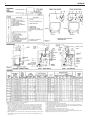
INTREPID
OIL-FIRED WATER AND STEAM BOILERS/NO. 2 OIL
INSTALLATION AND OPERATING INSTRUCTIONS
SAFETY WARNING:
KEEP BOILER AREA CLEAR AND FREE FROM
COMBUSTIBLE MATERIALS, GASOLINE AND
OTHER FLAMMABLE VAPORS AND LIQUIDS.
FAILURE TO ADHERE TO ABOVE SAFETY
WARNING, MAY RESULT IN PERSONAL INJURY
OR DEATH AND PROPERTY DAMAGE.
CONTENTS . . . . . . . . . . . . . . . . . . . . . . . . . . . . . . . . .PAGE
Ratings and Dimensions . . . . . . . . . . . . . . . . . . . . . . . . . . .2
Installation Requirements:
Boiler Location . . . . . . . . . . . . . . . . . . . . . . . . . . . . . . . .3
Clearances . . . . . . . . . . . . . . . . . . . . . . . . . . . . . . . . . . .3
Chimney Requirements . . . . . . . . . . . . . . . . . . . . . . . . .3
Air Supply and Venting . . . . . . . . . . . . . . . . . . . . . . . . . .3
Controls and Accessories . . . . . . . . . . . . . . . . . . . . . . . .6
Piping for Steam Boilers . . . . . . . . . . . . . . . . . . . . . . . . .6
Cleaning Piping System . . . . . . . . . . . . . . . . . . . . . . . . .6
Piping for Water Units . . . . . . . . . . . . . . . . . . . . . . . . . . .6
Piping for Tankless Heater . . . . . . . . . . . . . . . . . . . . . . .7
Installing Burner . . . . . . . . . . . . . . . . . . . . . . . . . . . . . . .7
Oil Supply Piping . . . . . . . . . . . . . . . . . . . . . . . . . . . . . .7
Wiring the Boiler . . . . . . . . . . . . . . . . . . . . . . . . . . . . . . .7
Vent Piping and Draft Regulator . . . . . . . . . . . . . . . . . . .8
Operating Instructions:
Precautions Before Starting . . . . . . . . . . . . . . . . . . . . . .8
Start-up . . . . . . . . . . . . . . . . . . . . . . . . . . . . . . . . . . . . . .8
Cleaning and Filling New Water Boiler . . . . . . . . . . . . . .8
Blowing Off a Steam Boiler . . . . . . . . . . . . . . . . . . . . .6, 9
Cleaning and Filling New Steam Boiler . . . . . . . . . . . . .9
Low Water Cut-off Check-out . . . . . . . . . . . . . . . . . . . . .9
Pressure Control Check-out . . . . . . . . . . . . . . . . . . . . .10
Replacement of Steam Boiler . . . . . . . . . . . . . . . . . . . .10
Wiring Diagrams . . . . . . . . . . . . . . . . . . . . . . . . . . . . .11-14
Burner Data . . . . . . . . . . . . . . . . . . . . . . . . . . . . . . . . .15-20
Care and Maintenance:
Extended Shutdown . . . . . . . . . . . . . . . . . . . . . . . . . . .21
Freezing Protection . . . . . . . . . . . . . . . . . . . . . . . . . . . .21
Oil Burner . . . . . . . . . . . . . . . . . . . . . . . . . . . . . . . . . . .21
General Maintenance . . . . . . . . . . . . . . . . . . . . . . . . . .21
IMPORTANT: The installation of this equipment must conform
to the requirements of the authority having jurisdiction or, in
the absence of such requirements, to the Installation of Oil
Burning Equipment, ANSI/NFPA 31, latest edition, and to the
National Electrical Code ANSI/NFPA 70, latest edition. The
installation must also conform to the additional requirements in
this Slant/Fin Instruction Manual. Where there is any difference, the more stringent requirement shall govern.
In addition, where required by the authority having jurisdiction,
the installation must conform to American Society of
Mechanical Engineers Safety Code for Controls and Safety
Devices for Automatically Fired Boilers, No. CSD-1, latest
edition.
THIS MANUAL MUST BE LEFT WITH OWNER AND
SHOULD BE HUNG ON OR ADJACENT TO THE
BOILER FOR REFERENCE.
IMPORTANT: This boiler must be installed by a trained,
experienced, service technician, licensed for the installation
and servicing of oil burning equipment or otherwise qualified by
the authorities having jurisdiction over the installation.
Printed in U.S.A. 207
Part No. 43-2764
Publication No. TR-40
INTREPID
2
Standard working pressure 30 psi water, 15 psi steam.
All boilers hydrostatically tested — A.S.M.E.
* For forced hot water heating systems where the boiler and all piping are located within
the area to be heated, the boiler may be selected on the basis of gross D.O.E. capacity
output. The net I=B=R output ratings shown are based on an allowance for piping and
pickup of 1.15 (water) or 1.33 (steam). D.O.E. capacity gross output is divided by the
allowance to obtain net rating. The manufacturer should be consulted before selecting a
boiler for unusual piping and pickup requirements such as intermittent system operation,
extensive piping, etc.
† Ratings apply to the use of light oil at 140,000 Btu per gallon, and apply only when burner
models listed on pages 14-16 of this manual are used, and are properly adjusted to produce 13% CO2.
§ Nominal clay tile liner dimensions.
** Tankless heater rating based on intermittent draw.
¶ Water boiler models TR-30 and larger have two firing rates. The boiler is factory shipped
at the lower firing rate. To obtain the higher firing rate, refer to the INTREPID boiler installation instructions for the appropriate field adjustments.
‡ I.B.R. gross output
q Collar is oblong, will fit 6" diameter nominal connector.
¢ This dimension is from the boiler jacket to the center of the flue outlet.
NOTE: All boilers under 300,000 Btuh input are tested and rated for capacity under the U.S.
Department of Energy (D.O.E.) test procedures for boilers.
3
INTREPID
INSTALLATION REQUIREMENTS
BOILER LOCATION
Provide a level, solid foundation for the boiler. Location should be near
the chimney so that the Flue Pipe Connector or Breeching to the chimney is short and direct.
A. The foundation must be capable of supporting the weight of
the boiler when filled with water:
Boiler
Size
Approximate Total Weight of Boiler
Assembly, filled with water
TR-20
TR-30
TR-40
TR-50
TR-60
TR-70
440
550
660
785
895
1000
B. The Intrepid Boiler has full wet base sections which surround firebox for maximum heat absorption of burning fuel, and low floor
temperature.
C. If boiler is to be located over buried conduit containing electric wires
or telephone cables, consult local codes or the National Board of Fire
Underwriters for specific requirements.
MINIMUM CLEARANCE
Provide accessibility clearance of 24" from surfaces requiring servicing
(top and front) and 18" on any side requiring passage. The boiler shall
be installed with the following MINIMUM clearances from combustible
materials:
A. CHIMNEY CONNECTOR-18"
B. BACK AND SIDES- 6" EXCEPT as limited by 18" clearance
from chimney connector
NOTE: Except in closets and alcoves, clearances above in (A) and
(B) may be reduced by providing forms of protection as specified in
NFPA 31, latest edition.
CHIMNEY REQUIREMENTS
A. The chimney must be constructed in accordance with all local applicable codes and the National Board of Fire Underwriters. See boiler
models and rating table shown on page 2 for chimney sizes.
B. Check chimney condition.
Existing chimneys and stacks may have deteriorated; without repairs
their use would be hazardous. Before connecting to an old chimney
or stack:
1. Clean it.
2. Inspect it thoroughly.
3. Remove obstructions.
4. Replace worn sections of metal stacks.
5. Seal bad masonry joints.
6. Repair damaged linings.
C. Where more than one appliance vents into a common chimney, the
area of the common breeching should at least equal the area of the
largest appliance flue plus 50% of the additional flue areas.
D. Breeching area must not be reduced at connection into chimney.
Breeching must be inserted into, but not beyond, inside of chimney
liner.
E. Chimney height shall extend at least 3 feet above where it passes
through the roof of the building, and at least 2 feet above any ridge
within 10 feet of the chimney.
F. The use of a vent cap, where permitted by code, gives additional
protection against adverse wind conditions and precipitation.
G. Flue Connection: Connect flue pipe between top of boiler and chimney. Horizontal sections of flue pipe must be pitched upward to the
chimney at least 1/4" per foot. Flue must be inserted into, but not
extend beyond, the inside wall of the chimney flue. Install draft regulator in flue pipe, as shown in figure 3.
AIR SUPPLY AND VENTILATION (see NFPA 31, latest edition)
Sufficient air for combustion and ventilation in the boiler room must be
provided. Failure to do this will result in poor combustion, heavy sooting and health hazards.
INTREPID
4
Any oil-fired boiler must have a steady draft* and an ample supply of
combustion air at all times during firing. If air supply or chimney draft* is
unreliable, CO2 and overfire draft* will change unpredictably.
the vent regulator into the living space. DO NOT operate this boiler and
a solid fuel burning appliance at the same time, unless the solid fuel
burner is provided with its own outside air supply.
DO NOT vent this boiler to the same chimney flue used by a fireplace or
coal or wood burning furnace or boiler. The draft* produced by solid
fueled devices varies tremendously between high fire and low fire:
See Table 2, “Provisions for Combustion and Ventilation Air Supply” for
determining need and method of providing air for combustion and
ventilation.
In modern, weather stripped, energy-saving buildings or older buildings
which have been modified similarly, natural infiltration may not supply
enough air for combustion, particularly if other fuel burning appliances,
exhaust fans or draft inducers are competing for the same air supply.
Fireplaces, other solid fuel burning appliances and exhaust fans consume great quantities of air; if air supply is not ample, such an appliance
will create a downdraft in the oil-fired boiler flue. This can create a hazardous condition. Flue gases can be sucked out of the chimney through
If fly screen must be used over air supply openings, areas calculated
should be doubled; the screen should be inspected and cleaned frequently to maintain free air flow.
Protect air openings against closure by snow, debris, etc. Openings such
as doors or windows, if used, must be locked open.
* Draft is negative or suction pressure
TABLE 2: Provisions for Combustion and Ventilation Air Supply. See NFPA 31, latest edition for more detailed information.
Boiler Location
Air Supply
Action Required
2.1
Unconfined space
Is there sufficient air for combustion by natural infiltration (see
NOTE (1), “Test...” below)?
NONE
2.2
Unconfined space
If there is NOT sufficient air for
combustion by natural infiltration
due to tight construction or other
conditions, then it REQUIRES AIR
FROM OUTDOORS. SEE
“ACTION REQUIRED” column at
right. See Notes (1) and (2) below.
Provide air from outdoors directly through a permanent outside
wall opening or openings with a free open area of not less than
1 sq. in. per 4000 Btu/hr of TOTAL input of ALL fuel burning
appliances in the building. See Note (1) and (3).
2.3
Confined space
If there is sufficient air for combustion from within building but it
comes from outside of the
confined space. SEE “ACTION
REQUIRED” column at right.
See Note (1) below.
2.4
Confined space
If there is NOT sufficient air for
combustion due to tight construction or other conditions it
REQUIRES AIR FROM OUTDOORS. SEE “ACTION
REQUIRED” column at right.
See NOTE (2) below.
The confined space shall be provided with two permanent air
openings, one near the top of the enclosure and one near the
bottom. EACH opening shall have a free air opening of not less
than 1 sq. in. per 1000 Btu/hr. of TOTAL input of ALL fuel burning
appliances within the enclosure. The two openings shall freely
communicate with the interior areas of the building which in turn
would have to have adequate infiltration of air from outdoors.
See Notes (1, 3) and Figure 3a.
(a) Air from the outdoors shall be provided to the confined space
by two permanent openings, one in or near the top of the
enclosure space and one in or near the bottom. The openings shall communicate directly, or by means of ducts, with
outdoors or to such spaces (crawl or attic) that freely communicate with outdoors (See figures 3b, 3c
and 3d).
(b) Where directly communicating with outdoors or by means of
vertical ducts, each opening shall have a free area of not
less than 1 sq. in. per 4,000 Btu/hr. (35 sq. in. per gal. per hr.)
of TOTAL input rating of ALL appliances in the enclosure. If
horizontal ducts are used, each opening shall have a free
area of not less than 1 sq. in. per 2,000 Btu/hr. (70 sq. in. per
gal. per hr.) of TOTAL input of ALL appliances in the confined
space. See Figures 3b, 3c and 3d.
(1) Test for sufficient air for combustion by infiltration by running this boiler for 30 minutes under all of the following conditions and at the same time: a) all doors, windows and other like openings must be closed, b) all fuel burning appliances should be FIRING, c) all exhaust fans and clothes dryers turned ON. At the above
conditions the CO2, smoke and draft readings must be normal. (CO2 between 11% and 13%, smoke between ZERO and a TRACE, draft between .02” W.C. and
.04” W.C. negative pressure.)
(2) Aside from tight construction, some of the conditions that steal air for combustion from a boiler are other fuel burning appliances, exhaust fans and clothes dryers.
(3) Generally, louvers made of wood have a free open area of 20% and those made of metal have a 60% to 70% free open area. Screens also reduce the open area
of the louvers.
5
INTREPID
Figure 3a.
Appliances located in confined spaces. Air from
inside the building. See Table 2 (2.3).
Figure 3b.
Appliances located in confined spaces. Air from outdoors. See Table 2 (2.4).
Figure 3c.
Appliances located in confined spaces. Air from outdoors through ventilated attic. See Table 2 (2.4).
Figure 3d.
Appliances located in confined spaces. All air from
outdoors through ventilated crawl space and outlet
air to ventilated attic. See Table 2 (2.4).
INTREPID
6
INSTALLING CONTROLS AND
ACCESSORIES ON BOILER UNITS
Note: Jacket must be installed on boiler units prior to installation
of trim.
I.
STEAM BOILER TRIM, see page 2 for tapping locations, and
figure 4 for illustration of steam boiler.
A. Steam pressure gauge and pressure cut-out, install in tapping
no. 4, figure 4.
B. Gauge glass set — use tapping no. 12.
C. Pop safety valve — use tapping no. 3, piped full size to boiler; or
pipe full size into a valveless steam header.
D. Combustion safety control — mounted on burner.
II. WATER BOILER TRIM, see page 2 for tapping locations, and figures 1 and 2 for illustration of water boiler.
A. Pressure- temperature - altitude gauge — use tapping no. 6.
B. High temperature limit — use tapping no. 7.
C. Operating control (if used) — use tapping no. 7.
D. Water relief valve — use tapping no. 3, piped full size to boiler.
E. Automatic air vent or compression tank tappings — if used,
install in tapping no. 2.
F. Combustion safety control — mounted on burner.
PIPING
IMPORTANT: Boilers are to be used with closed system. Any
application that uses steam or water from system, causes the introduction of a frequent supply of fresh water into the boiler. This will
cause damage to the boiler. Use of heat exchangers will prevent this
damage.
PIPING FOR STEAM BOILERS
Provide Header and Hartford Loop as suggested. See figures 4
and 5. Local codes apply.
CLEANING PIPING SYSTEM
A. To clean piping system, open all valves at the heating elements.
After getting up a good head of steam, shut the boiler down and
allow the condensate to return to the boiler. The condensate will
carry the oil film with it. Again blow-off the boiler. On extremely fouled
systems, it may require several visits over a few days to clean
the system.
B. When steam only (no water) is released through the hand valve,
the boiler will not surge or flood.
PIPING FOR WATER UNITS
NOTE: On knocked-down boiler only, jacket may be installed after supply and return piping connection, but must be installed prior to adding
trim.
I. CIRCULATING SYSTEM
A. FORCED CIRCULATION hot water heating system: Use the
top tapping as supply tapping, and use the front or rear bottom
tappings for the return.
B. A FLOW CONTROL VALVE (See figure 6) will prevent gravity
circulation and usually is required when tankless heater is
installed.
II. AIR CONTROL SYSTEMS
A. DIAPHRAGM-TYPE COMPRESSION TANKS are used to control system pressure in an AIR ELIMINATING SYSTEM:
an automatic air vent is used to REMOVE air from the system
water.See figure 6. If system pressure needs further control, add
an additional tank or install a larger capacity tank. The automatic
air vent should be installed in the top of the boiler, as in figure 6.
B. CONVENTIONAL COMPRESSION TANKS (non-diaphragm type)
are used to control system pressure in an AIR COLLECTING
SYSTEM. Within the system, after initial start-up and venting, air
is collected in the tank and acts in contact with the water to control pressure. Air is not vented from this system.
If system pressure needs further control, add another tank in
parallel with the original tank or install a large capacity tank.
Locate the tank at the inlet end of the pump near the boiler.
(See figure 7)
INTREPID
C. HOT WATER RADIATION VENTING - Manual air vents should be
installed at the top of all "drops"(where piping goes downward).
Air must be vented or purged from all zone lines to permit proper
system heating.
D. PUMP LOCATION-Locating low-head pump(s) on return to boiler is only acceptable in residences of one or two stories. (See
figure 6) The pump location shown in figure 7 is required in large,
multi-story building installations, especially when high-head
pumps are used and is also recommended for all applications.
E. A conventional compression tank may be connected to the 3/4"
tapping as shown in figure 7.
IMPORTANT: Hot water heating systems containing high water volume,
such as would occur with cast-iron radiation, require special care with air
elimination. The circulator pump should be located on the boiler supply
pipe and the expansion tank and air scoop should be located near the
pump suction. (See Figure 6, Alternate Pump Location.)
PIPING TANKLESS HEATER (if used)
I. Heater capacities are listed on Page 2.
II. Pipe the built-in tankless heater using the inlet and outlet tappings
indicated on the heater (figure 8).
A. Tempering valve (illustrated, but not furnished) is suggested to
provide more volume of temperate water to kitchen and bath.
B. High temperature water, for dishwasher and laundry, may be
piped direct.
C. A flow control valve should be used to control the rate of flow of
water through the coil, otherwise the heating capacity of the coil
will be exceeded. To insure sufficient hot water, the flow rate
through the coil should be limited to a maximum shown for intermittent draw in the ratings table on page 2.
INSTALLING THE BURNER
See Burner Data, pages 14-18, and Burner Manual supplied with burner. If burner is not mounted as received, mount to boiler, placing flange
over mounting studs. Use gasket between flange and boiler. Distance
between flange and nose of burner must be as shown on pages 14-18.
Check to see that nozzle and settings are as given in burner data tables,
pages 14-18.
OIL SUPPLY PIPING
Install the oil tank or tanks and piping from tank to burner. Follow local
codes and practices, NFPA No. 31, INSTALLATION OF OIL BURNING
EQUIPMENT and the instruction sheet attached to the oil burner pump.
A one-pipe system should be used for gravity-fed fuel systems and for lift
systems, where the total lift is less than 8 feet. Where the total lift is
greater than 8 feet, a two-pipe system must be used. In some
instances, local codes may require a two-pipe system for below grade
fuel oil tanks. Be sure to set-up the fuel oil pump for the piping system
used; follow the instructions attached to the pump. Be sure to include a
good quality, low pressure drop fuel oil filter in the supply line from the
tank. This is necessary, especially at low fuel oil flow rates (small nozzle
sizes), to prevent nozzle plugging. See Slant/Fin publication on one-pipe
and two-pipe fuel oil systems.
WIRING THE BOILER
A. The wiring diagrams for the burner and boiler may be found on
pages 11-13.
B. 24 volt control wiring should be approved Safety Circuit wire,
protected as needed.
C. Power supply wiring to the burner must be 14 gauge or heavier, as
required, and should have a properly fused disconnect switch. 120
volt wiring to pumps and safety controls must also be 14 gauge or
heavier. Wire must be enclosed in approved conduit.
D. All wiring must be installed in compliance with the National Electric
Code, or any local or insurance codes having jurisdiction.
7
INTREPID
8
VENT PIPING AND DRAFT REGULATOR
A. Vent pipes must be installed having the same diameter as the boiler
outlet. (See page 2)
B. Vent pipes and breeching must be pitched upward a minimum of 1/4"
per foot.
C. Connect vent pipe to the chimney using as few elbows as possible.
D. Horizontal vent connector into the chimney should not be inserted
beyond the inside wall of the chimney.
E. Install barometric draft regulator on horizontal breeching, near chimney, with hinge horizontal and face vertical. See manufacturer's
instructions packed in carton with barometric draft regulator.
F. If two or more appliances are used on the same chimney, see
CHIMNEY, page 3.
G. Make up all joints with minimum air leaks, secure with sheet metal
screws.
OPERATING INSTRUCTIONS
PRECAUTIONS BEFORE STARTING OIL BURNER
Make a positive check of A through F before starting burner:
A. Boiler and system are full of water. All air is vented from system.
See below.
B. All wiring is completed. See pages 11-13.
C. Oil supply is connected to the burner; nozzle is installed correctly; oil
valve is open at tank.
D. Smokepipe is connected to chimney.
E. All combustible materials are cleared away.
F. Combustion air supply is provided. See page 3.
G. Burner settings are adjusted as per pages 14-18 and as shown on
boiler jacket.
H. Main cast-iron door on which burner is mounted is bolted shut and
fiberglass rope seal is making good contact.
WARNING: NEVER OPERATE any natural draft* boiler
(Intrepid boiler is a natural draft boiler) with zero draft or overfire pressure: early failure of the burner, nozzle and chamber is
inevitable if you do. Use a draft gauge, and make sure that
overfire draft* is .02", minimum, during all operating conditions.
* Draft is negative or suction pressure.
START-UP (COMBUSTION TEST INSTRUMENTS MUST BE USED)
A. Make sure the boiler is installed and wired properly and is full of
water.
B. Open the observation door (on the front, above the burner).
C. Start the oil burner (see burner instructions for bleeding air from oil,
etc.). IMMEDIATELY, set burner air bands to obtain a bright fire without smoke or oil stain. Set the DRAFT REGULATOR to obtain .02"
overfire draft*. Take draft reading through slot in observation door.
D. Close the observation door. Allow the burner to fire for at least one
hour total firing time, to bake out the volatile binders in the combustion chamber before taking final combustion readings.
E. By alternate adjustment of the barometric draft regulator, the burner
air regulation and head regulation devices (whichever apply), set for
a trace of smoke and as close to 13% CO2 as you can. Then open
the air bands or shutter (whichever apply) an additional 1/8". This
should result in zero smoke with NO raw oil on the smoke paper and
a smooth light-off. DO NOT ATTEMPT TO SET FIRE BY EYE.
Flame retention burners may appear efficient and smoke free from
an inefficient 7% up to an overly high 14% CO2. However, a very low
CO2 can also result in poor ignition and raw (unburned) oil entering
the fire box. At very high CO2, any slight decrease in air flow for any
reason will cause incomplete combustion, with high smoke and dry
soot formation in the fire box.
F. If smoke reading is satisfactory, but CO2 can not be increased to a
satisfactory level (12% or better) or overfire draft of 0.02" W.C. can
not be obtained, check for proper sealing between sections, between
burner mounting plate and front section, around burner blast tube
and around flue collector and collar. If seal is not satisfactory, reseal
with furnace putty or silicone with a temperature rating of at least
400° F. (All safety precautions indicated on material package must
be followed.)
G. Once burner and draft have been set up, then smoke, CO2 and stack
temperature should be checked and recorded. If smoke is greater than
trace, review the burner instructions; replace the nozzle if necessary.
Normal smoke to be expected at approximately 13% CO2 is zero to
a trace.
CLEANING AND FILLING A NEW WATER BOILER
I. There are a number of commercial preparations available from your
distributor for cleaning and for corrosion protection conditioning the
internal (waterside) surfaces of boilers. Follow the preparation manufacturer’s instructions.
DANGER: Use CAUTION when handling chemicals and draining hot
water from a boiler. Scalding water and/or
chemicals can cause permanent injury to the skin, eyes
and respiratory system.
II. FILLING AND VENTING THE WATER BOILER
A. Refill the system with fresh water.
B. Bring water temperature to at least 180° F. promptly.
C. Circulate water through entire system.
D. Vent the system, including the radiation.
E. The boiler is now ready to be put into service or on standby.
F. If brand-name air-control devices are used, venting instructions
furnished with the devices should be followed.
III. SAFETY CHECK FOR CONTROL SYSTEM
High limit control test: Set thermostat high enough for boiler water
temperature to reach high limit control setting. When this temperature is reached, the high limit switch should open, and the burner
should shut off automatically. If the high limit does not operate to
shut off the burner, the high limit or the wiring is faulty. Repair or
replace immediately.
9
INTREPID
CLEANING AND FILLING A NEW STEAM BOILER
I. BEFORE USING STEAM BOILER
A. Check burner to be certain it is ready for firing. DO NOT FIRE
into an empty boiler.
B. Be prepared to heat raw water to at least 180°F. as soon as it is
introduced into the boiler. This procedure will remove dissolved,
corrosive gases.
C. Provide drain line, with valve, from boiler. Use a bottom tapping.
Line and drain must be suitable for handling caustic solution.
D. Check for low water cut-off operation, see section below for
check-out.
II. CLEAN STEAM BOILER SYSTEM.
A. Fill the boiler to water line indicated on the boiler.
B. Follow start-up procedure for burner and operate the boiler with
steam in the entire system for 2 or 3 days to bring oil and dirt
from the system to the boiler. While system is in operation,
maintain the proper water level in the boiler by slowly adding
water to the boiler.
C. Shut down burner, cool down boiler and drain system.
III. FILLING AND VENTING THE STEAM BOILER
A. Refill the boiler to the indicated water line.
B. Bring water to boiling temperature, promptly.
C. The boiler is now ready to be put into service or on standby.
BLOWING OFF A LOW PRESSURE STEAM BOILER
A. A 1-1/2" NPT tapping is provided in the front of the boiler (tapping
no. 9, figure 1) for use as a surface blow down to provide rapid
skimming of oil and grease which accumulate on the surface of the
water. The boiler should be blown down as outlined below.
B. Turn off electrical power supply to boiler. Allow boiler to cool down
and steam pressure to reduce to zero before removing skimmer
tapping plug. Check for steam pressure by testing the pop safety
valve. Keep your hands and all parts of your body away from the
discharge end of the safety valve. Drain boiler down one to two
inches below skimmer tapping. The water might be hot. Remove
skimmer plug slowly and carefully install a 150 psi malleable iron 11/2" NPT street elbow, a 1-1/2" NPT skimmer valve and length of
pipe and place a bucket underneath the open end of the pipe. Cover
bucket with a piece of cloth. (See figure 9)
C. Fill boiler slowly until water level is two inches from top of gauge
glass. (This is the starting water level for skimming only.) Fire boiler to
produce steam. If the system is heavily laden with oil, it may be difficult to obtain much more than a pound or so of pressure. Set the
pressure control at about 7 psi. The higher the steam pressure you
can use, the better and faster the cleaning.
D. As steam develops, open the SKIMMER drain valve with caution to
skim the oil and film from the top of the water. DO NOT open the boiler drain valve. Close the skimmer drain valve when the water level
drops to about 5" from the top of the gauge glass. The water may
stop before the level drops to 5" below the top of the glass. Refill boiler until water level is again two inches from the top of the gauge
glass.
E. Repeat (D) above until all film is skimmed off and the water settles to
a normal movement. Add make up fresh water to the boiler as
described in (D) above, during the blow-off operation, to maintain the
proper skimming water level in the vessel. Empty bucket frequently in
order to see the difference in water cleanliness.
F. When surging has stopped and water is clean, and no film can be
seen floating in the bucket, shut off boiler, drain down to level of skimmer tapping, remove valve, plug skimmer tapping and refill the boiler
to 24-1/2" water level. After 15 minute operation, readjust level to
normal operating level of 25-1/2" from bottom of boiler (see figure 9).
Check the pop safety valve for proper operation. Check the low water
cut-off operation, see below.
G. The entire process may have to be repeated over a period of a few
days on extremely fouled systems.
LOW WATER CUT-OFF CHECK-OUT
I. Electronic probe type low water cut-off
If this boiler is factory equipped with an electronic probe type low
water cut-off, operation of cut-off should be checked at least twice a
year as follows:
A. While boiler is running, drain down boiler water slowly through
Boiler Drain Cock shown on page 4, just until light goes on. Boiler
should shut down 10 seconds after light goes on.
B. Be sure that it is the low water cut-off and not the room thermostat, pressure cut-out, or other control that has shut off the burner.
C. Refill the boiler and repeat test.
D. Refill the boiler and reset controls for normal operation.
II. Float type low water cut-off
If this boiler is factory equipped with a McDonnell & Miller float type
low water cut-off, the low water cut-off must be blown down (flushed),
at least once a week.
10
CAUTION: When flushing float type low water cut-off control, hot water
and steam will flow out the blow down valve. Blow down valve is illustrated below.
A. SPECIAL FLUSHING INSTRUCTIONS
For new boiler installed in old system.
Installation of new boiler may break loose a heavy accumulation of
sediment and scale from old piping and radiators. It is extremely
important to blow down your McDonnell cut-off more frequently the
first week.
First week — 3 times
Thereafter — at least once a week.
B. As boiler water circulates through the float chamber, dirt or other
sediment may be deposited. This chamber is extra deep. But the
only sure way to keep any accumulation from interfering with float
action is to "blow down", or flush out, the control once a week. Do it
while boiler is in operation. First note water level in gauge glass.
Open blow-off valve at bottom of control; water will pour out, flushing away sediment. Drain until water is clear — about a pail —then
close valve. If level in gauge glass has dropped, add water to boiler
to restore level.
C. NOTE: Opening blow-off valve checks cut-off operation too. As
float drops with falling water level, burner will stop. After burner is
off and normal operating conditions restored, burner will resume
firing.
D. Be sure that it is the low water cut-off and not the room thermostat,
pressure cut-out, or other control that has shut off the burner.
INTREPID
PRESSURE CONTROL CHECK-OUT
A. Check burner to be certain it is ready for firing. DO NOT FIRE into
an empty boiler.
B. Set thermostat high enough for boiler to make steam. Set the pres
sure control down to its lowest setting. As the boiler starts to produce steam, the steam pressure will start to build. The burner will
shut off when the steam pressure exceeds the pressure setting
(plus differential if control has this feature).
C. Adjust the pressure control to a higher setting. The higher setting
should be above the steam pressure in the boiler. This should turn
the burner back on.
D. Reset the pressure control as needed for the system. The pressure
control should be checked at least twice a year.
REPLACEMENT OF STEAM BOILERS
Anytime an older steam boiler is removed from the heating system and
replaced with a new boiler, there are certain conditions that have to be
examined on the heating system.
A. Steam systems have a tendency to develop scale inside the wet
return lines and the boiler. The older the system the greater the
accumulation of scale that can exist inside the piping. Therefore, it
is necessary when replacing a steam boiler to check the piping for
blockage or restrictions. Clean or replace the piping as required.
(See special flushing instructions on this page.)
B. Replace all buried wet return lines.
C. All equipment (air vents, radiation equipment, etc.) in the steam
heating system should be checked for proper operation. All piping
should be checked for proper pitch.
D. It is good engineering practice to repack or tighten the packing nuts
on all valves in the heating system.
INTREPID
11
12
BASIC MODULE WIRING
(less circulator)
WIRING FOR PACKAGED STEAM BOILER EQUIPPED WITH McDONNELL NO.67 L.W.C.O.
INTREPID
INTREPID
WIRING FOR PACKAGED STEAM BOILER
For alternate option PS-801-120 L.W.C.O.
or Hydrolevel Cycle Gard 450 L.W.C.O.
BOILER WIRING DIAGRAM FOR RIELLO
13
14
STEAM BOILER WIRING FOR RIELLO BURNER AND McDONELL
MILLER P.S. 801 L.W.C.O. FOR CONNECTION TO LINE VOLTAGE
WALL THERMOSTAT (BY OTHERS)
WATER BOILER WIRING FOR RIELLO BURNER AND HIGH LIMIT,
LINE VOLTAGE WALL THERMOSTAT (BY OTHERS)
INTREPID
INTREPID
15
INTREPID
16
BURNER DATA – BECKETT CF-375 BURNERS FOR PACKAGED BOILERS ONLY
(For knocked-down & boiler burner units see publication no. TR-42KB)
Nozzles
†
*
Boiler
Model
Burner
Model *
Firing Rate
(GPH)
TR-60
TR-60
TR-70
TR-70
TR-70
CF-375
CF-375
CF-375
CF-375
CF-375
2.60
2.85
3.00
3.10
3.35
Size
(GPH)
2.25
2.25
2.5
2.5
2.75
Angle &
Type
45˚
45˚
45˚
45˚
45˚
P
P
SS
SS
B
Air shutter and air band settings shown are approximate ONLY.
See START-UP page 8.
All burner models shown are single stage.
MFG
Oil Pump Pressure
Setting (PSIG)
Air Shutter
Setting †
Air Band
Setting
Head
Setting
HAGO
HAGO
HAGO
HAGO
DELEVAN
135
160
145
155
148
10
10
10
10
10
3
2
4
4
4
1
2
3
4
5
INTREPID
17
INTREPID
18
BURNER DATA – RIELLO (continued)
FIgure 9B
MODEL F-10
ELECTRODE SETTING
SETTING THE AIR ADJUSTMENT PLATE (See figure 11)
1. The hydraulic AIR SHUTTER (A) is operated by the HYDRAULIC
JACK (F), assuring complete opening of the combustion air intake.
Regulation of the combustion air flow is made by adjustment of the
manual AIR ADJUSTMENT PLATE (D) after loosening the FIXING
SCREWS (C and E). The initial setting of the air adjustment plate
should be made according to page 16.
2. The proper number on the manual AIR ADJUSTMENT PLATE (D)
should line up with the SETTING INDICATOR (B) on the fan housing
cover. Once set, the air adjustment plate should be secured in place
by tightening SCREWS C and E. Manually open and release the
hydraulic air shutter to ensure it has free movement.
3. The final position of the air adjustment plate will vary on each installation. Use instruments to establish the proper settings for maximum
CO2 and a smoke reading of zero.
NOTE:
Variations in flue gas, smoke, CO2 and temperature readings
may be experienced when the burner cover is put in place.
Therefore, the burner cover must be in place when making
the final combustion instrument readings, to ensure proper
test results.
FIgure 11
NOTE: ELECTRODES ARE PRESET AT THE FACTORY.
REGULATION OF THE TURBULATOR AND AIR SHUTTER FOR
PROPER COMBUSTION
Turbulator Setting
1. Loosen nut, 1, then turn the screw, 2, until the index marker, 3, is
aligned with the correct index number.
2. Retighten the retaining nut, 1.
TURBULATOR SETTINGS - RIELLO 40 SERIES
The numbers on the casting are there to denote the high and low end of
the scale — in all cases the first mark if "Zero".
The air/oil ratio depends on accurate setting of the turbulator disc.
Be careful when making this adjustment as an incorrect setting will result
in an unsatisfactory installation. See figures 10A and 10B.
FIgure 10A
FIgure 12
FOR PROPER INSERTION INTO COMBUSTION CHAMBER
FIgure 10B
INTREPID
19
20
INTREPID
21
INTREPID
CARE AND MAINTENANCE
I. EXTENDED SHUTDOWN, CLEANING OR REMOVAL OF BOILER
FROM SERVICE.
DANGER: Use CAUTION when handling chemicals and draining hot
water from a boiler. Scalding water and/or chemicals can cause permanent injury to the skin, eyes and respiratory system.
A. Shut down burner by disconnecting all electrical power to the
burner by turning OFF the BURNER EMERGENCY SWITCH of
this boiler. After shutting down burner, while the boiler is still hot
(180°F to 200°F), drain water from the bottom of the boiler until it
runs clear.
B. Provide corrosion protection conditioning to the boiler water in the
heating system. There are a number of commercial heating system preparations available from your distributor. Follow the preparation manufacturer’s instructions.
1. For steam boilers, maintain a sodium chromate solution
strength of 16 oz. per 50 gallons of water; and refill to the top
of the gauge glass.
2. For water boilers, maintain a sodium chromate solution
strength of 6 oz. per 50 gallons of water, and refill to normal
fill-pressure with system vented.
3. Raise water temperature to at least 180°F. for one hour to
release dissolved gases.
4. Shut down burner by disconnecting the main switch.
C. To clean the fireside boiler surfaces, first shut down burner by disconnecting all electrical power to the burner by turning OFF the
OIL BURNER EMERGENCY SWITCH of this boiler in order to
perform the following work in (1) through (10) below.
1. Remove the flue pipe from the boiler flue collar and clean
thoroughly.
2. Inspect the entire vent connector back to the chimney and
clean if necessary.
3. Inspect the chimney for soot, debris and other unsafe conditions of the chimney and take the necessary action.
4. Remove the flue collector by first removing the top jacket
panel. The flue collector is held in place by two hex 1/4-20
screws. Remove the screws and carefully remove the flue collector. Try not to disturb the flat fiberglass rope under the flue
collector.
5. When necessary to clean the combustion chamber you must
first CLOSE the suction valve (and return valve if two pipe).
Then disconnect the oil lines from the burner. The flexible
electric conduit connected from the junction box on the boiler
to the burner via a plastic connector must be disconnected
from the burner by grasping the plastic half of the connector
closest to the flexible conduit and gently pulling it in the direction of the conduit until it is disconnected. Remove the single
3/8-16 hex head screw on the LEFT side of the swinging door.
You will need a 9/16” drive socket. Open the door to completely expose the combustion chamber for thorough cleaning and
for inspection of target wall, blanket (provided in certain models; see rating plate), main cast iron burner door insulation
and burner door fiberglass sealing rope. If combustion chamber parts above are badly deteriorated then replace with original factory parts available at your distributor.
6. Use the flue brush to clean the pinned flueways between the
sections.† A wire brush may be used to remove any carbon
accumulation that may have developed in the combustion
chamber. Vacuum the loose soot and debris from the boiler.
7. Inspect the burner combustion head. Clean if necessary and
make sure all the adjustments are correct. (See burner data
pages for the burner installed.) Replace oil nozzle with new
one and readjust electrodes. To insure proper burner operation ONLY THE NOZZLES SPECIFIED IN THIS MANUAL OR
ON THE BURNER LABEL SHOULD BE USED FOR
REPLACEMENT.
8. Close main cast iron burner door (door on which burner is
mounted). Make sure that the entire seal (fiberglass rope) is
making good contact with the boiler casting when replacing
3/8-16 x 1” long hex head bolt and tightening.
9. Check the flue collector seal. This is the flat rope seal on top of the
heat exchanger. The rope must be in place adjacent to the long bosses on front and rear sections and adjacent to the short bosses on the
intermediate sections. The rope should be directly under the flue collector flanges when the flue collector is replaced. Use the two 1/4-20
x 3/4” washer hex head screws to fasten the flue collector. In order to
assure a proper seal be sure that the flue collector is compressing
the flat rope and not hanging up on the section bosses. Tighten the
two screws.
D. If boiler room is damp, provide ventilation.
II. PROVIDING PROTECTION FOR FREEZING
Anti-freeze is sometimes used in hydronic heating systems to protect against freeze-up in the event of power failure, or safety control
shutdown when the building is unoccupied. It should be recognized
that unless the building is kept above freezing temperature by some
means, the plumbing system is not protected.
PROPYLENE GLYCOL is used in the quick-freeze food industry; it is
practically non-toxic. Its use may be permitted when tankless heaters
are used. When anti-freeze must be used, inhibited propylene glycol
is recommended. Useful information on the characteristics, mixing
proportions, etc. of glycol in heating systems is given in Technical
Topics No. 2A, available from the Hydronics Institute, 35 Russo
Place, Berkeley Heights, N.J. 07922. Consult glycol manufacturers
for sources of propylene glycol. DO NOT use ethylene glycol
because it is toxic.
III. OIL BURNER
Inspect and clean annually and following any period of improper
operation. Recheck and adjust settings as specified for burner model
and nozzle size. Set burner air and draft regulator, using test instruments to obtain recommended CO2 and draft without smoke.
Refer to page 8.
IV. GENERAL MAINTENANCE
These operations are recommended to be performed at regular
intervals:
A. BOILER HEATING SURFACES: clean off all coatings found.
Reseal covers.
B. BOILER CONTROLS: check contacts, settings, correct
functioning.
C. PIPING: check piping and accessories for leaks.
D. CHIMNEY or STUB VENT and BREECHING: check for obstructions and leaks.
E. COMBUSTION AIR TO BURNER: check for continued POSITIVE
supply of air as required. Air needs are greatest in coldest
weather. Refer to AIR SUPPLY, page 3.
F. WATER SYSTEM: check
1. System to be full of water and pressure to remain stable
(between 12 psi and 25 psi).
2. Air-control system: noise and air binding in radiation should
not occur.
3. Water lines: slightest leaks should be corrected.
4. Low water cut-off, for operation (see instructions furnished
with unit). See page 9.
G.STEAM SYSTEM: check
1. Low water cut-off, for operation (see instructions furnished
with unit). See page 9.
2. Check pressure cut-off for operation. See page 10.
3. Any unusual water conditions. Obtain water analysis and treat
water.
H. BOILER ROOM AIR SUPPLY: air vents should be open and free
of obstruction. See page 3.
†
A flue brush (2-1/4" dia.) is supplied with boiler. Replacements
are available from dealer or hardware stores.
-
-
SLANT/FIN CORPORATION, Greenvale, N.Y. 11548 • Phone: (516) 484-2600
FAX: (516) 484-5921 • Canada: Slant/Fin LTD/LTEE, Mississauga, Ontario
www.slantfin.com