1
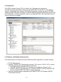
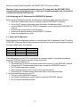
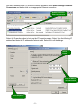
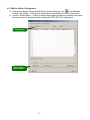
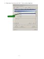
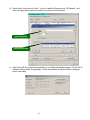
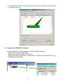
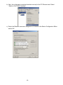
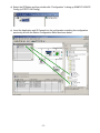
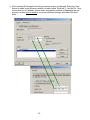
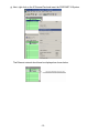
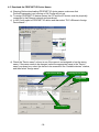
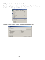
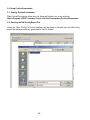
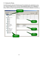
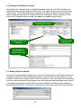
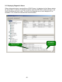
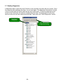
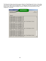
ProfinetCommander User Manual V1.0 July 2006 -1- ProfinetCommander User Manual V1.0 Table of Contents ProfinetCommander User Manual V1.0 ........................................................................................2 1.0 Version History ...............................................................................................................2 2.0 Introduction.....................................................................................................................3 3.0 Hardware and Software Requirements ..........................................................................3 4.0 Configuring the PC Station and the PROFINET IO Network ..........................................4 4.1 Select the IP Addresses .................................................................................................4 4.2 Edit the Station Configuration .........................................................................................6 4.3 Configure the PROFINET IO Network ............................................................................9 4.4 Download the Configuration to the PC Station .............................................................16 4.5 Download the PROFINET IO Device Names................................................................18 4.6 Exporting the Hardware Configuration to a File ............................................................19 5.0 Using ProfinetCommander ...........................................................................................20 5.1 Starting ProfinetCommander ........................................................................................20 5.2 Opening the HW Config Export File..............................................................................20 5.3 Configuration Display....................................................................................................21 5.4 Setting the Run Mode to Operate .................................................................................22 5.5 Setting IO Device Outputs ............................................................................................22 5.6 Displaying Diagnostic Alarms .......................................................................................23 5.7 Reading Diagnostics.....................................................................................................24 1.0 Version History Version 1.0: Release -2- 2.0 Introduction The PROFI Interface Center (PIC) in Johnson City, Tennessee has created the ProfinetCommander application, which runs as a PROFINET IO controller on a PC with an easy-to-use graphical user interface. With ProfinetCommander, the user can test a PROFINET network and the IO Devices connected to it. With the Windows graphical interface the user can view the configuration, I/O data, parameters, alarms, and diagnostic data. The output data to the IO devices can also be changed. 3.0 Hardware and Software Requirements The following items are required for the ProfinetCommander application to operate correctly. • • • PC with Ethernet port Siemens “SIMATIC NET Networking for Industry” CD, version 11/2003 + SP1 or newer. The following software must be installed from the CD: SOFTNET PN IO (PROFINET IO controller communications software for PC) SIMATIC NCM PC (configuration tool). If Siemens STEP7 is already installed, it will be used instead (STEP7 V5.3 SP3 or newer is required). Windows operating system supported by the SIMATIC NET CD (Windows 2000/XP Professional, see CD). -3- Before running ProfinetCommander the SIMATIC NET CD must be installed. Warning: If you have a firewall installed on your PC, it may block the SOFTNET PN IO communications on the Ethernet port. In this case ProfinetCommander will not be able to communicate with the PNIO devices. 4.0 Configuring the PC Station and the PROFINET IO Network Before starting ProfinetCommander, the following configuration steps must be performed: Select the IP addresses for the PC and the connected PROFINET IO devices. Set up the PC station configuration using the Station Configuration Editor. Use the SIMATIC NCM PC (or STEP7) configuration tool to configure the PROFINET IO network. Download the configuration to the PC station. Download the device names to the PROFINET IO devices. Export the configuration to a file. 4.1 Select the IP Addresses Before starting the configuration process you should select the IP addresses for the PC and the PROFINET IO devices that will be connected so that they are all on the same network and have the same subnet mask. For example: IP Address Subnet Mask PC 192.168.1.51 255.255.255.0 IO Device 1 192.168.1.1 255.255.255.0 IO Device 2 192.168.1.2 255.255.255.0 If the Ethernet port on your PC is connected to a corporate network, it would be advisable to keep the PROFINET network separate. Some options are: 1. Use the existing Ethernet port: • Disconnect the PC from the corporate network and connect it to the PROFINET network. • Change the PC IP address and subnet mask to match the PROFINET network. • Run ProfinetCommander software. • When finished, connect the PC back to the corporate network. • Restore the PC IP address and subnet mask back to their original settings. 2. Add a second Ethernet port to the PC: • Connect it to the PROFINET network • Set a fixed IP address and subnet mask to match the PROFINET network • Run ProfinetCommander software. -4- Set the IP address on the PC using the Windows software. Select Start->Settings->Network Connections and double-click on the appropriate Ethernet connection. Double-click on the Ethernet connection Select the Properties button to bring up the IP Properties screen. Select “Use the following IP address” and enter the IP address and subnet mask. Select OK in all the dialogs. Select button Enter IP address and Subnet mask Select Properties -5- 4.2 Edit the Station Configuration a) Execute the Station Configuration Editor by double-clicking its icon in the Windows System Tray toolbar. It can also be called up from the desktop icon or the Start menu. b) Use the “Station Name…” button to set the station name as desired (remember the name because it must be used later when creating the PROFINET IO configuration). Station Name Click to Change Station Name -6- c) Select Index 1 and then use the “Add…” button to add an Application. Add Application -7- d) Select Index 2 and use the “Add…” button to add the Ethernet card, “IE General”, and select the appropriate card if more than one exists as shown below. Select IE General Select Ethernet Card e) After hitting OK the component properties of your Ethernet Adapter appear. Check the IP address, subnet mask, and gateway. Select the Network Properties button if changes need to be made. -8- f) Check that the Run/Stop column has green indicators. If not, select the Diagnostics tab to determine the error. Configuration OK 4.3 Configure the PROFINET IO Network a) Execute SIMATIC NCM PC Manager (or STEP7 SIMATIC Manager). Create a new project with File->New. Select “Insert->Station->SIMATIC PC Station”. Change the name to match the PC station name in the Station Configuration Editor (e.g., PCStation) as shown below. -9- b) Next, the configuration download interface is set up for the PC Ethernet card. Select “Options->Set PG/PC Interface”. c) Select the Ethernet card that is assigned to IE General in the Station Configuration Editor and hit OK. - 10 - d) Select the PCStation and then double-click “Configuration” to bring up SIMATIC NCM PC Config (or STEP7 HW Config). e) Insert the Application and IE General into the configuration matching the configuration previously set with the Station Configuration Editor as shown below. - 11 - f) After inserting IE General the following properties screen is displayed. Select the ‘New’ button to create a new Ethernet network, normally called “Ethernet(1)”, and hit OK. Now ensure that your IP address, subnet mask, and gateway address (if applicable) are set properly, as they need to match your current Windows settings, and select OK when done. - 12 - g) Next, right click on the IE General Card and insert the PROFINET IO System. The Ethernet network should now be displayed as shown below. - 13 - h) Drag and drop the desired PROFINET IO devices from the catalog in the right window (under the PROFINET IO category) to the Ethernet(1) line and insert the appropriate modules in the lower left window as shown below. Also, when a device is inserted, set the IP address as shown below. - 14 - i) Double-click each PROFINET IO Device to display its properties and set the Device Name. The device name must match the name in the physical device. Downloading a name to an IO device is described later. If the IP address is not correct, select “Ethernet…” to change it. Make sure the IP address for IE General and the IP addresses for the IO devices are on the same network (addresses match through the subnet mask number of bits). Note: when the IO controller starts communication with the IO device, it will find the device by name and then set the IP address to this configured value. - 15 - j) Save and compile the project HW configuration by selecting the icon shown. Save and Compile 4.4 Download the Configuration to the PC Station a) Warning: If you are changing an existing configuration, make sure that ProfinetCommander is not running before downloading or HW Config will lock up. b) Download the configuration by selecting the icon shown. Download c) Select OK or Yes to all the dialog pop-ups. In the “Select Node Address” window, make sure that the “Station name” field has the PC Station name and the “CPU name” field has “IE General”. If not, then there is a configuration mismatch between HW Config and the Station Configuration Editor, and the download will not work. Check the PC IP address in both configurations. Fix the mismatch and try again. Station name must be present “IE General “ must be present - 16 - d) If there is an error during the download, call up the Station Configuration Editor and select the “Diagnostics” tab. Check the messages at the top that correspond to the time of download. - 17 - 4.5 Download the PROFINET IO Device Names a) Warning: Before downloading PROFINET IO device names, make sure that ProfinetCommander is not running or HW Config will lock up. b) To assign PROFINET IO device names, the PC and the IO devices must be physically connected to the Ethernet network and operational. c) In HW Config select a PROFINET IO device and then select “PLC->Ethernet->Assign DeviceName…”. d) Check the “Device name” column to see if the name is not assigned or has the wrong name. If the name needs to be changed, select the appropriate name in the “Device name” pop-down box, select the device to be renamed in the “Available devices” window, and then select “Assign name”. Select Device Name Existing Device Name Assign name Select Device - 18 - 4.6 Exporting the Hardware Configuration to a File The hardware configuration must be exported to a file. The exported file provides the information for ProfinetCommander to display the configuration data and to communicate with the I/O devices. In HW Config select “Station->Export…”. Designate an export file name, select the “Readable” format, and select Save. - 19 - 5.0 Using ProfinetCommander 5.1 Starting ProfinetCommander Start ProfinetCommander either from the Windows Desktop icon or by selecting Start->Program->PROFI Interface Center->ProfinetCommander->ProfinetCommander. 5.2 Opening the HW Config Export File Select the “Open Config File” button and then use the dialog to find and open the HW Config export file that was previously generated for the PC Station. - 20 - 5.3 Configuration Display ProfinetCommander reads the HW Config export file and displays the configuration in a tree view in the Configuration window. The tree can be expanded to show all the configured items (e.g., PCStation, PNIO devices, I/O modules, PROFINET/PROFIBUS proxies, PROFIBUS slaves). When a tree item is selected its properties and I/O data are displayed as shown below. Device Number from Config Devices Window Properties Window Alarms Window Configuration Window - 21 - 5.4 Setting the Run Mode to Operate After clicking the “Operate” button, ProfinetCommander functions as a PNIO controller and establishes communication with the PNIO devices. The Alarms window logs each device as it comes online. The I/O data and status is displayed in the Devices window. Note that the I/O data for all the modules under the selected tree item is displayed. When in Operate or Clear mode, the I/O data and status, and also the alarms, are updated every 500 ms. Set Run Mode to Operate Double-click cell to Change Output I/O Data and Status are Displayed Controller goes to Operate Mode and Devices come online 5.5 Setting IO Device Outputs As shown in the figure above, double-click a cell in the Output column of the Devices window to change the output. The following dialog will appear. Enter a value in the edit window to send constant output values to the IO device. Select “Increment” to make the output count up starting from its current value each 500 ms display cycle. Note that there may be multiple output values in the display separated by spaces. Each one can be edited for the Manual mode (leave the spaces between entries). If “Increment” is selected, all of the listed outputs will be incremented. - 22 - 5.6 Displaying Diagnostic Alarms When a diagnostic alarm is received from a PNIO Device, it is displayed in the Alarms window as shown below. At startup, ProfinetCommander reads the GSD files for all the devices to get text for the diagnostic error codes. The text for the diagnostic error is also displayed if it is available. If not, consult the manufacturers documentation. Error Text from GSD File (if it exists) Diagnostic Alarm - 23 - 5.7 Reading Diagnostics A diagnostic alarm is sent from the IO device to the controller only when the error occurs. Once the controller acknowledges the alarm, it is not sent again. The diagnostic information is stored in the IO device and can still be read until the error goes away. To read the diagnostic errors stored in the IO devices, first select a Configuration tree item. The diagnostics for all of the devices under the tree item selected will be read. Then select the “Read Diagnostics” button. First Select Config Item Then Call Up Read Diagnostics Dialog - 24 - The Diagnostic dialog shown below appears. Select the “Read Diagnostics” button in this dialog each time you want to read the diagnostics. The diagnostics have time stamps and are listed in reverse order, with the latest message at the top. A blank line is inserted each time “Read Diagnostics” is selected. Read Diagnostics Stored in IO Devices - 25 -