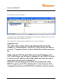
1
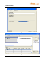
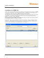
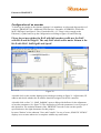
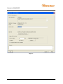
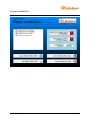
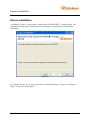
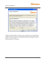
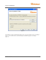
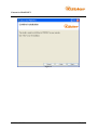
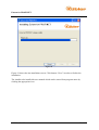
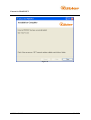
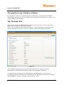
Ezturn for PROFINET
EZTURN for PROFINET
User manual
© Kübler GmbH
1 of 51
Ezturn for PROFINET
Table of contents
Table of contents ........................................................................................................................ 2
Preface........................................................................................................................................ 3
Abbreviations ............................................................................................................................. 3
System requirements .................................................................................................................. 3
Prerequisites for Ezturn for PROFINET .................................................................................... 4
Installation of SIMATIC NCM PC Software............................................................................. 4
Configuration of the PC with SIMATIC NCM or STEP7 ......................................................... 7
Installation of a GSDML file ............................................................................................... 20
Configuration of an encoder................................................................................................. 21
Station Configuration ........................................................................................................... 23
Project compilation and download....................................................................................... 28
Installation of Ezturn software ................................................................................................. 32
Ezturn installation .................................................................................................................... 34
Tab "Encoder info"................................................................................................................... 40
Tab "Operating parameters"..................................................................................................... 41
Tab "Warnings and Errors" ...................................................................................................... 42
Tab "Monitor" .......................................................................................................................... 43
Tab "Firmware updater"........................................................................................................... 44
Firmware updater error codes .............................................................................................. 45
Troubleshooting ....................................................................................................................... 47
References ................................................................................................................................ 51
Version of document ................................................................................................................ 51
© Kübler GmbH
2 of 51
Ezturn for PROFINET
Preface
The graphical user interface of Ezturn for PROFINET was developed with the intention to be
self-explanatory as far as possible. However there are few situations which need to be
described in order to support users understanding for this tool.
Also the user should show certain level of PROFINET knowledge in order to be able to
configure an encoder and to use Ezturn. Such a knowledge is represented by the respective
specifications. They are listed at the end of this document in chapter "References".
Abbreviations
GUI
FW
SW
Graphical User Interface
Firmware
Software
System requirements
Operating System:
CPU:
RAM:
Free Disk space:
WinXP SP 3, Win7
min 1GHz
min 512MB
500MB (mainly .NET 3.5 environment if not installed yet)
For installation of Ezturn for PROFINET administrator rights are required. If you do not have
administrator rights, please contact your system administrator.
© Kübler GmbH
3 of 51
Ezturn for PROFINET
Prerequisites for Ezturn for PROFINET
The prerequisites for communication of an Ezturn PC station with Kübler PROFINET
encoder are:
•
STEP 7 Version V5.4 or SIMATIC NCM PC Version V5.4 + SP4 +HF1, Revision
Level K5.4.4.1
•
A license for SOFTNET PN IO Edition 2008 MLFB: 6GK1 704-1HW71-3AA0
Installation of SIMATIC NCM PC Software
•
•
•
•
•
•
Insert the SIMATIC NCM PC CD into CD – ROM drive
In the installation screen select to install the software
Select your preferred language
Accept conditions of license agreement
Provide user and company name information and click button "Next"
In the next screen, see figure 1, select to install all software components apart from
Acrobat Reader, unless you need to do so, and click button "Next".
Figure 1
© Kübler GmbH
4 of 51
Ezturn for PROFINET
Once the installer has installed all software packets, the user is prompted to transfer license
keys or to step ahead within the installation. See next figure.
Figure 2
The preferred decision is to skip license installation at this time point and to click button
"Next". With the next screen, see figure 3, the computer should be rebooted.
© Kübler GmbH
5 of 51
Ezturn for PROFINET
Figure 3
After reboot, start the Automation License Manager and install License keys which you
purchased for STEP 7 or SIMATIC NCM PC and PNIOBASE-Library. Read the
corresponding SIEMENS documentation in case you do not know how to do this.
© Kübler GmbH
6 of 51
Ezturn for PROFINET
Configuration of the PC with SIMATIC NCM or STEP7
Ezturn for PROFINET is a Windows based application. The communication between the PC
which runs Ezturn and the PROFINET encoder is established with SIEMENS SOFTNET
PNIO BASE library. The following figures show how to configure the PC with SIMATIC
NCM PC Version 5.4 which is a trimmed down version of STEP7.
Start SIMATIC NCM Manager from the program menu. A screen as per figure 4 appears.
Figure 4
In menu "File" select submenu "New" and create a new project, e.g.
PNIOBASE_FOR_EZTURN, see figure 5, and press button OK.
© Kübler GmbH
7 of 51
Ezturn for PROFINET
Figure 5
As per figure 6, right click the new created entry PNIOBASE_FOR_EZTURN and select the
insertion of a new object of type "SIMATIC PC Station".
Insert an object of type "Industrial ethernet".
Figure 6
© Kübler GmbH
8 of 51
Ezturn for PROFINET
The final result is shown in figure 7.
Figure 7
Left click on entry "EzturnStation" which changes contents in the right part of the screen and
then double click on the "Configuration" item.
The configuration window which is started this way, is shown in figure 8.
IMPORTANT !
The name of the station which runs Ezturn in this particular
example is "EzturnStation" and HAS TO BE exactly the same as
given by "Computer Name" in the Control Panel of the respective
PC.
If the respective PC has more than one network interface card
(NIC) and at least one of them is configured to use DHCP in order
to retrieve an IP-Address, then either make sure that the card is
connected to the network or disable it.
Otherwise the operating system (Win XP) permanently sends
DHCP-requests on all NICs which leads to a break down of the
communication betweeen PROFINET controller and the encoder.
© Kübler GmbH
9 of 51
Ezturn for PROFINET
Figure 8
In the left upper window which has the title "(0)PC" right click on the first line and choose to
insert an object of category "CP Industrial Ethernet / IE General / SW V7.1"
The action of selecting this object is visible in figure 9.
As final result, SIMATIC NCM PC opens a configuration dialog according to figure 10.
Adjust the IP address and subnet mask according to your needs.
© Kübler GmbH
10 of 51
Ezturn for PROFINET
Figure 9
© Kübler GmbH
11 of 51
Ezturn for PROFINET
Figure 10
Right click on line 2 within the window, entitled "(0)PC" and select to insert an object of
category "User Application / Application / SW V6.3". The action itself and its result are
documented in figures 11 and 12.
© Kübler GmbH
12 of 51
Ezturn for PROFINET
Figure 11
© Kübler GmbH
13 of 51
Ezturn for PROFINET
Figure 12
A double click on the "Application" entry opens a dialog which allows for change of name,
see figure 13, and also to change the Communication Processor Index known as VFD. For
Ezturn the VFD configuration must be set according to figure 14.
© Kübler GmbH
14 of 51
Ezturn for PROFINET
Figure 13
© Kübler GmbH
15 of 51
Ezturn for PROFINET
Figure 14
The PC running Ezturn must be configured as PNIO-Controller. This is done by a double
click on entry "IE General PNIO" which opens a dialog according to figure 15 and its tabs
depicted in figures 16 and 17.
Important:
By checking the check box "IO controller" in figure 17, SIMATIC
NCM PC automatically attaches the Ethernet segment to the PC
Station. See figure 18.
Now set the IP address in the control panel according to value
selected in figure 10 !
© Kübler GmbH
16 of 51
Ezturn for PROFINET
Figure 15
© Kübler GmbH
17 of 51
Ezturn for PROFINET
Figure 16
© Kübler GmbH
18 of 51
Ezturn for PROFINET
Figure 17
Figure 18
© Kübler GmbH
19 of 51
Ezturn for PROFINET
Installation of a GSDML file
At this time point the encoder needs to be configured. For this purpose the respective GSDML
file has to be installed first. The corresponding encoder's GSDML file can be found on the
accompanying Ezturn CD which is shipped out along with an encoder.
The name of the most current GSDML file, at the time point when this document was written
is GSDML-V2.2-Kuebler-SendixAbsolute-20101229.xml. The accompanying bitmap is
Kuebler_sendix58x8_70x40_24bit.bmp.
During installation, the GSDML and the bitmap file need to be in the same directory in order
to be found by SIMATIC NCM PC or STEP 7.
In the HW Config window according to figure 18, select menu "Options" submenu "Install
GSD File..." and navigate to the directory which incorporates the GSDML and bitmap file.
Select the XML file and press the "Install" button, as per figure 19.
Figure 19
© Kübler GmbH
20 of 51
Ezturn for PROFINET
Configuration of an encoder
To hook up an encoder to the ethernet segment, it is mandatory to select and drag an object of
category "PROFINET IO / Additional Field Devices / Encoders / KUEBLER / DAP with
MAP, StdTelgr81 and Speed / 58xx_EncoderProfile_4.1". Drop it close enough to the
Ethernet(1) symbol and set up the configuration according to figures 20 and following.
Please do not use neither the DAP with full encoder profile nor the DAP
with MAP and StdTelgr81. The only DAP which works under Ezturn is the
DAP with MAP, StdTelgr81 and Speed !
Figure 20
A double click on the encoder bitmap opens a dialog according to figure 21. Adjust name, IP
address and decide whether the IP address should be assigned via the IO controller.
A double click on line "1,1: MAP_SubMod" opens a dialog which allows for the adjustment
of encoder parameters. See figure 22. The description of encoder parameters is out of scope of
this document. The technical manual of the PROFINET encoder or the encoder profile
specification are the right documents for this purpose.
In menu "Station" select submenu "Save and Compile". In case of errors, SIMATIC NCM PC
displays error reasons otherwise it completes without any notification.
© Kübler GmbH
21 of 51
Ezturn for PROFINET
Figure 21
© Kübler GmbH
22 of 51
Ezturn for PROFINET
Figure 22
Station Configuration
The PC must be now configured in order to set up a communication with the encoder.
Start the Station Configuration Editor, which was installed at the time SIMATIC NCM PC
was installed. Figure 23 shows the corresponding dialog.
© Kübler GmbH
23 of 51
Ezturn for PROFINET
Figure 23
Press button "Add..." and select "IE General" as component type in the "Add component"
dialog. See figure 24.
The Index HAS TO BE 1.
The "Parameter assignment" combo box provides choice for the network card if there are
more than one installed in the PC. Select the right one and press button OK. Confirm the
warning notification and "Component Properties" dialog by clicking button OK. If successful
the result will appear as per figure 25.
© Kübler GmbH
24 of 51
Ezturn for PROFINET
Figure 24
© Kübler GmbH
25 of 51
Ezturn for PROFINET
Figure 25
Repeat now the component add action adding an application according to dialog in figure 26.
On success the result is given as shown in figure 27.
© Kübler GmbH
26 of 51
Ezturn for PROFINET
Figure 26
© Kübler GmbH
27 of 51
Ezturn for PROFINET
Figure 27
Project compilation and download
Now we download the saved and compiled project configuration itself.
In window SIMATIC NCM Manager highlight entry "EzturnStation" and select menu
"Options" submenu "Set PG/PC interface...". In the dialog opened, select entry
"TCP/IP(Auto)->..." followed by the name of your network interface card which will be the
access point for the PNIOBASE application. See figure 28.
If your network interface card is of type Broadcom then please read chapter
"Troubleshooting" section 3 at the end of this document.
© Kübler GmbH
28 of 51
Ezturn for PROFINET
Figure 28
Note: at this time point the IP address of the station must be set according to figure 10. Hence
192.168.0.1 in this particular example. This is mandatory, otherwise the download that
follows will not work.
In menu "PLC" select submenu "Download" which displays a warning and a notification
according to figure 29.
Figure 29
© Kübler GmbH
29 of 51
Ezturn for PROFINET
If this error indication occurs, change the station name either within Windows control panel
subitem system or within Station Configuration Editor (see figure 30) such that both names
are identical.
Figure 30
In the case that both names are identical, SIMATIC NCM displays a dialog and prompts the
user to choose the right download target. According to figure 31 highlight all modules and
press button OK.
© Kübler GmbH
30 of 51
Ezturn for PROFINET
Figure 31
SIMATIC NCM PC displays now a notification about stopping of target modules. Then the
download begins displaying the progress as depicted in figure 32.
Figure 32
With the project download completed, the configuration is done and the system is ready to be
used.
© Kübler GmbH
31 of 51
Ezturn for PROFINET
Installation of Ezturn software
Please close all applications before you start the setup program for Ezturn. A reboot is
required after installation.
Insert CD into CD drive. The setup starts automatically. If it does not, double click on
CDStart.exe in the root directory of the CD. A setup screen appears as depicted in figure 33
below.
The recommended sequence of program installation is:
-
Click entry "Installation of Ezturn for PROFINET" in the left upper tree view of the
installation screen
Click button "View Ezturn installation manual for PROFINET" in order to open this
document and to get more information on installation
Click button "View technical manual for PROFINET encoder" if you want to get
information on how to take a PROFINET encoder into operation.
Click button "Install Ezturn for PROFINET"
There is one situation where setup reboots the PC without user interaction. This is
automatically detected and applies for all PCs where setup needs to install the .NET
environment first. .NET environment is a prerequisite for Ezturn. Please leave the installation
CD in the CDROM drive in this situation.
© Kübler GmbH
32 of 51
Ezturn for PROFINET
Figure 33
© Kübler GmbH
33 of 51
Ezturn for PROFINET
Ezturn installation
According to figure 33 press button “Install Ezturn for PROFINET” to install Ezturn. The
installation wizard starts as depicted in following figure 34 and guides you through the
installation.
Figure 34
Press button "Next". If you agree upon license, check radio button “I Agree” according to
figure 35 and press button “Next”.
© Kübler GmbH
34 of 51
Ezturn for PROFINET
Figure 35
Change the installation folder name in the next screen or simply keep it as suggested by the
installation wizard which is the preferred installation method. If you want to allow all users
who have an account on the PC to use Ezturn software then select radio button “Everyone”
otherwise “Just me”, see figure 36.
Then press button “Next” to continue.
© Kübler GmbH
35 of 51
Ezturn for PROFINET
Figure 36
The installer is ready to install Ezturn software now. If you press button “Next” according to
figure 37, the installer starts to install and displays installation progress according to
figure 38.
© Kübler GmbH
36 of 51
Ezturn for PROFINET
Figure 37
© Kübler GmbH
37 of 51
Ezturn for PROFINET
Figure 38
Figure 39 shows the last installation screen. Click button “Close” in order to finalize the
installation.
The installer also installs this user manual which can be started from program menu by
clicking the appropriate icon.
© Kübler GmbH
38 of 51
Ezturn for PROFINET
Figure 39
© Kübler GmbH
39 of 51
Ezturn for PROFINET
The graphical user interface of Ezturn
For information on how to install the encoder, which cables are defined for PROFINET,
which blink codes and errors are provided by the encoder itself and much more, please see the
TechnicalManual.pdf document.
Tab "Encoder info"
When started, Ezturn for PROFINET displays the tab "Encoder info" which is the first in a
sequence of five tabs. See following figure 40.
With a click on button "Read values from encoder", Ezturn establishes connectivity to the
encoder and reads all respective values or indicates connectivity problems otherwise.
Figure 40
The information displayed herein represents the MAC address, Identification and
Maintenance record information and part of the operating status information.
A comprehensive description of the Identification and Maintenance record exists in
specification "Profile Guidelines Part1: Identification & Maintenance Functions for Profibus
and PROFINET" Version 1.2 October 2009 Order No: 3.502.
© Kübler GmbH
40 of 51
Ezturn for PROFINET
A comprehensive description of the operating status info is available in the encoder profile
specification. See document "Profile Encoder, Technical Specification for Profibus and
PROFINET related to PROFIdrive Version 4.1 December 2008. OrderNo: 3.162".
Tab "Operating parameters"
Figure 41 depicts elements of tab "Operating parameters" which are read-only within Ezturn
for PROFINET. This is because operating parameters are set by SIMATIC NCM as soon as
the connection is being established between SIMATIC NCM PC and the encoder. See
previous chapters.
A description of operating parameters is part of the encoder profile specification and is known
as user parameter data to be send to the encoder using index 0xBF00.
Figure 41
© Kübler GmbH
41 of 51
Ezturn for PROFINET
Tab "Warnings and Errors"
This tab shows which warnings and errors are basically supported by the encoder and if they
occurred at the time point of reading.
Figure 42
© Kübler GmbH
42 of 51
Ezturn for PROFINET
Tab "Monitor"
The purpose of the monitor tab is to visualize cyclic data. Single turn value in the "Singleturn"
gauge, the combination of single and multi turn value in the "Position value" edit field, speed
in the "Speed" gauge. Members of the standard telegram, ZSW2_ENC and G1_ZSW are
displayed in the group box "Actual value". Finally, the user is able to read and to set the
preset value and to start or stop monitoring by buttons in the "Monitor control" group box.
Figure 43
© Kübler GmbH
43 of 51
Ezturn for PROFINET
Tab "Firmware updater"
The purpose of the firmware updater is to replace the firmware of the PROFINET encoder.
See figure 44. Pressing the button "Select firmware image file" opens a file dialog and permits
a file to be selected.
The file name including path will be displayed in the "Firmware image location" box.
The index into which records are written is 0x3D00 and is shown within the tab in the
corresponding place.
With a click on button "Start firmware update", the firmware updater reads the file size and
displays its value in bytes. This is the total number of bytes to be sent.
The maximal number of bytes per frame or the "chunk size" is 471. This value is shown in the
next line.
Having the total number of bytes to send and the maximal size of bytes per record, the updater
calculates the maximal number of frames to send and displays this value within the tab.
The overall update progress is visualized by value "Number of frames successfully
transmitted" and the graphical indication by the progress bar.
Any errors are indicated by an appropriate message. If the update is successful, the updater
displays a message "FW update successfully finished !".
With the next reset, the image will be used as active application. This however can be
achieved just by clicking button "Reset encoder".
Important:
The update process can be interrupted at any time. There will be no influence on the
active image in this case, even after reset. However, with the successfully written last
frame of the update image file, the active image will be replaced within approximately 5
seconds. This time point is the "point of no return".
© Kübler GmbH
44 of 51
Ezturn for PROFINET
Figure 44
Firmware updater error codes
The PROFINET IO status within the firmware updater is based on IEC 61158 and is
expressed by values of ErrCode, ErrDecode, ErrCode1 and ErrCode2.
For the duration of firmware update, following errors can occur and have the following
meaning:
Meaning
CRC error
FW image size not ok
Number of bytes per frame not ok
Encoder is busy
State conflict
Wrong frame type sent
© Kübler GmbH
ErrCode
0xDF
0xDF
0xDF
0xDF
0xDF
0xDF
ErrDecode
0x80
0x80
0x80
0x80
0x80
0x80
ErrCode1
0xDF
0xD1
0xD2
0xD3
0xD5
0xD9
45 of 51
Ezturn for PROFINET
Other errors are visualized as well although their meaning is out of scope of this document. A
good summary of all error codes is available in the book "Industrielle Kommunikation mit
PROFINET" by Manfred Popp.
© Kübler GmbH
46 of 51
Ezturn for PROFINET
Troubleshooting
In case of problems when taking a PROFINET encoder into operation, please make sure that:
1. The station name in the hardware configuration of STEP7 or SIMATIC NCM PC is
identical with the PC name
2. The firewall is disabled for the network interface card which communicates with the
PROFINET encoder
3. In case of Broadcom network interface cards of type NetLink4XX, please install driver
from DVD directory ... BroadcomDriver\NetLink440. In case of NetXtreme drivers please
install driver from directory ...BroadcomDriver\NetXtreme.
4. If you can not establish connectivity to the encoder at all, select the PC/PG interface
according to figure 28. Then browse the network from Step7 menu "PLC/Edit Ethernet
Node...". See figure 45 below. In the following dialog which is shown in figure 46, press
button "Browse..." in order to start the bus scan.
Figure 45
© Kübler GmbH
47 of 51
Ezturn for PROFINET
Figure 46
If the network card hardware works and was successfully installed along with its
corresponding driver then the bus scan ends up with the shown encoder connected to the PC.
In the example of figure 47 the encoders name is sendix58xx.
© Kübler GmbH
48 of 51
Ezturn for PROFINET
Figure 47
5. Under some circumstances the connectivity to the encoder is not established on the PC/PG
interface of the specific network interface card installed, see figure 48, but simply on the
generic interface "PC internal (local)" according to figure 49. If both interfaces do not
work then please check hardware and driver installation.
© Kübler GmbH
49 of 51
Ezturn for PROFINET
Figure 48
Figure 49
© Kübler GmbH
50 of 51
Ezturn for PROFINET
References
•
Profile Encoder, Technical Specification for Profibus and PROFINET related to
PROFIdrive Version 4.1 December 2008. OrderNo: 3.162
•
Profile Drive Technology PROFIdrive Technical Specification for PROFIBUS and
PROFINET Version 4.1 May 2006. OrderNo: 3.172
•
Profile Guidelines Part1 : Identification & Maintenance Functions for Profibus and
PROFINET Version 1.2 October 2009. Order No: 3.502
•
Technical manual TechnicalManual.pdf for PROFINET Kübler GmbH
Version of document
Version No
1.0
1.1
1.2
1.3
1.4
Date
17. 05. 2010
26. 05. 2010
01.10.2010
14.10.2010
12.11.2010
1.5
1.6
09.12.2010
18.02.2011
1.7
17. Mai 2011
© Kübler GmbH
Modifications
First complete version
Figures updated
Revised revision
Working version for Win7
Break down of PROFINET communication by
DHCP requests
Chapter "Troubleshooting" added
References to GSDML-V2.2-KueblerSendixAbsolute-20101229.xml added
Some new troubleshooting aspects added
51 of 51