1
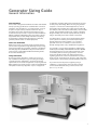
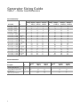
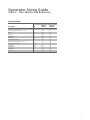
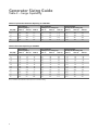
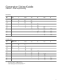
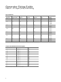
Sizing Guide
standby
GENERATORS
Generator Sizing Guide
General Information
Important Notice
This booklet is designed to familiarize estimators and installers
with proper sizing guidelines for residential and commercial
generators. The information is not comprehensive, nor does
it replace or supercede any material contained in any of
the written documents shipped with the equipment. This
booklet should only be used in conjunction with the Owner’s
Manual, Installation Manual and other technical documents
shipped with each product. Always read all accompanying
documentation carefully before attempting to install any
generator, transfer switch or related equipment.
How to Use this Booklet
Within this booklet, you will find electrical load information,
plus an outline of generator surge capability, fuel pipe sizing,
liquid propane tank sizing, and UPS / generator compatibility.
The final pages are perforated for easy removal and can be
photocopied to create additional Onsite Estimating Sheets
for use with individual jobs.
Safety Information
Proper sizing of the generator is crucial to the success of
any installation and requires a good working knowledge
of electricity and its characteristics, as well as the varying
requirements of the electrical equipment comprising the load.
When analyzing the electrical load, consult the manufacturer’s
nameplate on each major appliance or piece of equipment
to determine its starting and running requirements in terms
of watts, amps and voltage. When choosing the generator
output for commercial or industrial applications, select a
rating that is approximately 25% higher than the peak load
(for example, if the load is about 40 kilowatts, select a 50 kW
genset). A higher rated generator will operate comfortably
at approximately 80% of its full capacity and will provide a
margin of flexibility if the load increases in the future.
For safety reasons, Siemens recommends that the backup
power system be installed, serviced and repaired by a
Generac Authorized Service Dealer or a competent,
qualified electrician or installation technician who is
familiar with applicable codes, standards and regulations.
It is essential to comply with all regulations established by
the Occupational Safety and Health Administration (OSHA)
and strict adherence to all local, state and national codes
is mandatory. Before selecting a generator, check for
municipal ordinances that may dictate requirements
regarding placement of the unit (setback from building
and/or lot line), electrical wiring, gas piping, fuel storage (for
liquid propane or diesel tanks), sound and exhaust emissions.
If you have a technical question regarding sizing or
installation, contact Siemens Technical Service Center
toll free at 800-844-0029 during normal business hours
(8 a.m. to 5 p.m. CST).
1
Generator Sizing Guide
Table 1 – Motor Load Reference
AC and Heat Pumps
Running Load
Description
1 Ton (12,000 BTU)
2 Ton (24,000 BTU)
3 Ton (36,000 BTU)
4 Ton (48,000 BTU)
5 Ton (60,000 BTU)
7.5 Ton (85,000 BTU)
10 Ton (120,000 BTU)
10 Ton (120,000 BTU)
15 Ton (180,000 BTU)
15 Ton (180,000 BTU)
20 Ton (240,000 BTU)
20 Ton (240,000 BTU)
25 Ton (300,000 BTU)
30 Ton (360,000 BTU)
30 Ton (360,000 BTU)
40 Ton (480,000 BTU)
40 Ton (480,000 BTU)
50 Ton (480,000 BTU)
50 Ton (480,000 BTU)
Hp
1
2
3
4
5
7.5
5 Hp (x2)
10 Hp
7.5 Hp (x2)
15 Hp
10 Hp (x2)
20 Hp
25
15 Hp (x2)
30 Hp
20 Hp (x2)
40 Hp
25 Hp (x2)
50 Hp
Running
kW
1
2
3
4
5
7.5
10
10
15
15
20
20
25
30
30
40
40
50
50
Amps at
240V 1ø
5
10
15
20
25
37
49
49
74
74
98
n/a
n/a
n/a
n/a
n/a
n/a
n/a
n/a
Starting Load
Amps at
208V 3ø
3
7
10
13
16
24
33
33
49
49
65
65
82
98
98
131
131
163
163
Amps at
480V 3ø
1
3
4
6
7
11
14
14
21
21
28
28
35
42
42
57
57
71
71
Starting
kW
3
6
9
12
15
17
15
20
17
30
20
40
50
30
60
40
80
50
100
LR Amps
at 240V 1ø
25
50
75
100
125
188
125
250
188
375
250
500
625
375
750
500
1000
625
1250
LR Amps
at 208V 3ø
17
33
50
67
83
125
83
167
125
250
167
333
416
250
500
333
666
416
833
LR Amps
at 480V 3ø
7
14
22
29
36
54
36
72
54
108
72
144
180
108
217
144
289
180
361
General Residential
Running Load
Description
Refrigerator, Sump Pump,
Furnace, Garage Opener
Freezer, Washer, Septic Grinder
General 1 Hp
Well and Septic Lift Pump
2
Starting Load
Hp
0.5
Running
kW
0.5
Amps at
120V 1ø
4.9
Amps at
240V 1ø
2.5
Starting
kW
1.5
LR Amps
120V 1ø
25
LR Amps
240V 1ø
13
0.75
1
2
0.75
1
2
7.4
9.8
19.6
3.7
4.9
9.8
2.3
3
6
38
50
100
19
25
50
Generator Sizing Guide
Table 2 – Non-Motor Load Reference
General Residential
Running Load
Description
Electric heat per 1000 ft.2
Heat pump elements per 1000 ft.2
Dryer
Hot tub
Range oven
Hot water
Stove top per burner
General receptacles per 1000 ft.2
Lighting per 1000 ft.2
Blow dryer
Dishwasher
Microwave
Toasters
kW
12
7
5.5
5
5
4.5
1.5
1
0.75
1.25
1.5
1
1
Amps at
120V 1ø
n/a
n/a
n/a
n/a
n/a
n/a
n/a
8.3
6.3
10.4
12.5
8.3
8.3
Amps at
240V 1ø
50
29
23
21
21
19
6
n/a
n/a
n/a
n/a
n/a
n/a
3
Generator Sizing Guide
Table 3 – Surge Capability
Siemens Liquid Cooled Generators Operating at <3600 RPM
Size (kW)
25
70
80
100
130
Rated Output
(Running Amps)
240V 1ø
208V 3ø
104
87
292
243
333
278
417
347
542
451
480V 3ø
38
105
120
150
195
Surge Capability
LR Amps at 15% Voltage Dip
240V 1ø
208V 3ø
480V 3ø
71
47
26
275
183
106
275
183
106
371
247
142
546
364
209
Surge Capability
LR Amps at 30% Voltage Dip
240V 1ø
208V 3ø
480V 3ø
133
89
52
550
366
212
550
366
212
738
491
284
1088
724
419
Surge Capability
LR Amps at 15% Voltage Dip
240V 1ø
208V 3ø
480V 3ø
23
n/a
n/a
31
n/a
n/a
38
n/a
n/a
46
n/a
n/a
63
42
24
71
47
26
104
69
40
146
97
57
179
119
69
246
164
95
333
222
128
558
372
215
Surge Capability
LR Amps at 30% Voltage Dip
240V 1ø
208V 3ø
480V 3ø
46
n/a
n/a
63
n/a
n/a
75
n/a
n/a
92
n/a
n/a
121
80
47
138
92
53
204
136
78
292
194
112
354
236
136
496
330
190
663
441
255
1121
747
431
Siemens Generators Operating at 3600 RPM
Size (kW)
7
10
13
16
20
25
35
45
60
70
100
150
Rated Output
(Running Amps)
240V 1ø
208V 3ø
29
24
42
35
54
45
67
56
83
69
104
87
146
121
188
156
250
208
292
243
417
347
625
520
480V 3ø
11
15
20
24
30
38
53
68
90
105
150
226
Note: All kW models listed above are based on nominal LP rating.
4
Generator Sizing Guide
Table 4 – Fuel Pipe Sizing
Natural Gas
kW
7
10
13
16
20
25
35
45
60
70
80
100
130
150
Pipe Size (in.)
0.75"
55
20
10
1"
200
85
50
40
20
10
1.25"
820
370
245
190
115
75
35
15
1.5"
800
545
425
265
180
95
60
25
5
2"
2.5"
3"
915
650
390
225
195
140
50
30
1185
710
630
460
215
150
2"
2.5"
3"
1030
725
445
260
230
165
70
45
1095
660
590
430
205
150
1305
660
490
950
660
370
260
145
75
65
40
LP vapor (LPV)
kW
7
10
13
16
20
25
35
45
60
70
80
100
130
150
Pipe Size (in.)
0.75"
165
70
45
30
15
1"
570
255
170
130
80
50
20
1.25"
1000
690
540
340
235
125
82
45
20
15
1.5"
745
520
290
195
115
60
50
30
Note: – Table values are maximum pipe run in feet.
– Pipe sizing is based on .5" H2O pressure drop.
– Sizing includes a nominal number of elbows and tees.
– Please verify adequate service and meter sizing.
5
Generator Sizing Guide
Table 5 – LP Vapor (LPV) Tank Sizing
Vapor Withdrawal
Tank Capacity
Total (Gal.)
Tank Capacity
Useable (Gal.)
Length
(Inches)
Diameter
(Inches)
Overall Ht.
(Inches)
Minimum Temp
(°F)
Tank Capacity
(btu/hr.)
40
20
0
40
20
0
40
20
0
40
20
0
40
20
0
40
20
0
40
20
0
246,240
164,160
82,080
293,760
195,840
97,920
507,600
338,400
169,200
642,600
428,400
214,200
792,540
528,360
264,180
1,217,700
811,800
405,900
1,416,960
944,640
472,320
120
72
57
24
33
150
90
68
24
33
250
150
94
30
39
325
195
119
30
39
500
300
119
37
46
850
510
165
41
50
1000
600
192
41
50
Note: Tank BTU capacity and generator run times based upon maintaining a minimum tank fuel level of 20%.
LP Vapor (LPV) Withdrawal Fuel Consumption
Load (kW)
BTU / Hr
Gal / Hr
7
10
13
16
20
25
35
45
60
70
80
100
130
150
110,000
190,000
215,000
252,000
340,000
390,000
500,000
620,000
800,000
950,000
1,100,000
1,400,000
1,800,000
2,050,000
1.2
2.1
2.4
2.8
3.8
4.3
5.5
6.8
8.8
10.5
12.2
15.5
19.9
22.7
Note: Fuel consumption based on a generator 80% loaded.
6
Generator Sizing Guide
UPS Generator Compatibility
Passive (also referenced as standby or off-line) and
Line-Interactive
These technologies are most common for personal workstations
and point of sale applications. They are typically single phase
equipment with size ranges of 350 VA – 2000 VA for passive
and 500 VA to 5000 VA for line-interactive.
Passive UPS’s are the simplest type. Under normal conditions
AC power passes straight through to the UPS load. When the
input power supply goes outside of specifications, the UPS
transfers the load from input power to the internal DC to AC
power inverter. Passive UPS’s do not correct for voltage or
frequency deviations under “normal” operation.
Line-interactive is similar to the passive technology except
it has circuitry that attempts to correct for standard voltage
deviations. Frequency deviations under “normal” power
operation are not corrected.
Equipment Notes:
These devices tend to be electrically / harmonically very noisy.
A single small UPS is not a significant concern, but applications
with multiple UPS’s can be problematic.
Passive UPS technology typically has normal tolerances of
10 – 25% on voltage and 3 hertz on frequency. If the input
source goes outside of these tolerances, the UPS will switch
onto the UPS battery source. Some line-interactive units may
have frequency tolerances factory set to .5 hertz. These units
will need to have their frequency tolerance increased to a
minimum of 2 hertz.
Double-Conversion
This technology is most common for critical load applications.
Double-conversion UPS’s constantly rectify AC to DC and then
invert the DC back into AC. This configuration results in an
output that corrects for voltage and frequency deviations.
There are single and three phase models covering small
through large applications. Most UPS applications larger than
5000 VA use double conversion technology. This approach is
also the preferred technology for generator applications.
Equipment Notes:
Double-conversion UPS’s that are single phase or unfiltered
three phase models tend to create a significant level of
electrical/ harmonic noise. This is illustrated by harmonic
current distortions that are greater than 35%. When three
phase models are supplied with harmonic filters (current
distortion less than 10%), this concern is no longer an issue.
Generator Sizing Recommendation:
Single phase models: limit the total UPS loading to 25%
of the generator capacity.
Three phase models without filters (current distortion > 30%):
limit the UPS loading to 35% of the generator capacity.
Three phase models with filters (current distortion < 10%):
limit the UPS loading to 80% of the generator capacity.
Generator Sizing Recommendation:
Limit the total UPS loading to 15% – 20% of the generator
capacity.
Supplier(s)
Passive (Standby)
Line-Interactive
Double-Conversion
APC
Back-UPS Series
Smart-UPS Series
Symmetra Series
Liebert
PowerSure PST and PSP
PowerSure PSA and PSI
UPStation and Nfinity Series
Powerware
3000 Series
5000 Series
9000 Series
Note: Ferrups and Delta-Conversion UPS technologies not included in discussion.
7
Generator Sizing Guide
Onsite Estimating Sheet
Contractor _____________________________________________
Email _________________________________________________
Phone _________________________ Fax ___________________
Job Name _____________________________________________
Date___________ Location _______________________________
120/240 1Ø
VOLTAGE
Natural Gas
TYPE
ELEC. SERVICE 100 Amp
600 Amp
120/208 3Ø 277/480 3Ø
LP Vapor LPV)
200 Amp
400 Amp
Other________
Before installation contact local jurisdiction to confirm all
requirements are met. Jurisdictions may vary. Siemens
recommends contacting local authorities prior to installation.
Loads: Look for heavy building loads such as refrigeration,
air conditioning, pumps or UPS systems.
Use the following for sizing and determining generator kW.
Table 6
Motor Load Table (refer to Table 1)
Device
HP RA LRA kW Running
(= HP)
Starting
kW QT Upgrade Required
These applications require an upgrade from the QT Series:
NEC 695 Fire Pumps
NEC 700 Emergency Systems
NFPA 20 Fire Pumps
NFPA 99 Healthcare
NFPA 110 Emergency Systems
Reference Codes
Related Codes and Standards:
NEC 225 Branch Circuits and Feeders
NEC 240 Overcurrent Protection
NEC 250 Grounding
NEC 445 Generators
NEC 701 Legally Required Standby
NEC 702 Optional Standby
NFPA 37 Installation and Use of Stationary Engines
NFPA 54 National Fuel Gas Code
NFPA 58 LP Gas Code
To Calculate kW
120 V 1Ø
240 V 1Ø
208 V 3Ø
240 V 3Ø
480 V 3Ø
(refer to page 2 for shortcut)
Amps x 120/1000 = kW
Amps x 240/1000 = kW
Amps x 208 x √3 x PF/1000 = kW
Amps x 240 x √3 x PF/1000 = kW
Amps x 480 x √3 x PF/1000 = kW
PF is application power factor (worst case 1.0)
Typical application power factor is 0.95.
Resources in Sizing Guide
Surge Capability Chart – References running amps of units and LRA
Propane Tank Sizing Chart – Measures fuel consumption of generator units
Motor Load Reference Guide – Reference guide for basic motor loads
Non-Motor Load Reference Guide – Reference guide for non-motor loads
Fuel Piping Sizing Chart – Assists in calculating adequate pipe size for
natural gas and propane
UPS – Generator Compatibility
Starting kW for HP < 7.5 starting kW = HP x 3
Starting kW for HP > 7.5 starting kW = HP x 2
Starting kW for loading with no listed HP, calculate HP based on running amps
in the chart on the right.
Table 7
Non-Motor Load Table (refer to Table 2)
Device
Amps
kW
UPS Information
1.5 x kVA rating for a filtered system
3 – 5 x kVA rating for an unfiltered system
Siemens recommends you refer to the Siemens UPS Generator
Compatibility sheet and notify the manufacturer of the UPS
system to assist in your installation.
Transfer Switch Availability
SR6ST – 100 and 200 Amp service entrance rated
RTS
– 100, 200, 400 Amp
SR6SI switch only works with R100 controller.
XT 6XR – 100, 150, 200, 300, 400, 600, 800 Amp
HTS switch only works with H100 controller. Avail. in
NEMA 1, NEMA 3R and NEMA 12. Refer to Siemens
product catalog for the appropriate transfer switch.
Recommended Generator Size ________ Refer to Generator Sizing Instructions on other side of this sheet.
INSTALL NOTES:
1. Suggested concrete pad minimum thickness of 4" with 12" overhang on all sides. Fiberglass pad included with air-cooled products.
2. Consult manual for installation recommendations.
3. Consult local authority having jurisdiction for local requirements.
8
Generator Sizing Guide
Onsite Estimating Sheet
Generator Sizing Instructions:
There is not a single correct sizing solution. The instructions
below identify multiple methods that, when mixed with good
judgment, should result in a moderately sized generator.
Remember to consider load growth, seasonality, and effects
of starting motors.
When motors start, they create a current surge that step loads
the generator. As a result of this step loading, the generator
will experience a voltage dip. After selecting a generator,
reference the generator's surge capability using Table 3. Verify
that the generator voltage dip is adequate for the application.
Most commercial applications should be limited to 15%
voltage dip and residential applications should be limited to
30% voltage dip.
Some commercial applications utilize one or multiple
uninterruptible power supplies (UPS) to backup critical loads.
Please read sizing guidelines for this load type.
Measurement Method
Use a clamp-on amp meter or power analyzer to measure facility load levels. The measurement should be made at peak load
levels. Size the generator 25% larger than the peak measured
load. Verify motor and UPS load compatibility.
Measured Amps = _______
Billing History Method
Many commercial customers have a utility rate structure that
has a peak demand charge. Using a year's worth of electric
bills, size the generator 25% larger than the largest peak
demand. Verify motor and UPS load compatibility.
Peak Demand = _______
Load Summation Method
1) Enter all motors loads expected to run during peak load
levels into Table 6. Reference Table 1 for typical motor sizes
and electrical requirements.
2) Enter all non-motor loads expected to run during peak load
levels into Table 7. Reference Table 2 for typical residential
loads and rules of thumb.
3) Sum the running motor load data but do not include
the largest motor that is cycling. Add to this value the
non-motor load data and the starting kW for the largest
cycling motor.
Motor running load total
(minus largest cycling motor):
______ kW (Ref. Table 6)
Motor starting load from
largest cycling motor:
+ ______ kW (Ref. Table 6)
Non-motor load total:
+ ______ kW (Ref. Table 7)
Total (above items):
= ______ kW
Select generator (Total x 1.25)
______ kW
4) Verify voltage dip compatibility using generator Surge
Capability Table 3. Verify UPS compatibility using sizing
guidelines provided.
Initial Estimate and Cross Check Methods
These methods are for initial estimates and cross checks only.
Size the generator using one of the above methods.
Estimate based on 60% service size:
240 Volts, 1Ø: ________ amps x .15 = ________ kW
208 Volts, 3Ø: ________ amps x .22 = ________ kW
480 Volts, 3Ø: ________ amps x .50 = ________ kW
Estimate Based on Square Footage
Fast food, convenience stores, restaurants, grocery stores
= 50 kW + 10 watts / sq. ft.
Other commercial = 30 kW + 5 watts / sq. ft.
Square footage = ____________
Estimated kW
= ____________
LP
LPG: 8.55 ft.3/lb., 4.24 lbs./gal.,
2500 btu/ft.3
LPG: 36 ft.3 = 1 gal.
Natural Gas
1 cubic foot = 1,000 BTUs
1 therm = 100,000 BTUs
Gas consumption = 13,000-16,000 btu
per kW/hr.
Pressure
1 inch mercury = 13.61 inches
Water Column
1 inch Water Column = 0.036 psi
5-14 inches water column = 0.18 psi
to 0.50 psi
Air Conditioning
1 hp per 1 ton
1 ton = 12,000 btu
Rule of Thumb
For 480 volt systems kW x 1.5 = Amps
For 208 volt systems kW x 3.5 = Amps
For 240 volt single phase systems
kW x 4 = Amps
9
Generator Sizing Guide
Onsite Estimating Sheet
Contractor _____________________________________________
Email _________________________________________________
Phone _________________________ Fax ___________________
Job Name _____________________________________________
Date___________ Location _______________________________
120/240 1Ø
VOLTAGE
Natural Gas
TYPE
ELEC. SERVICE 100 Amp
600 Amp
120/208 3Ø 277/480 3Ø
LP Vapor LPV)
200 Amp
400 Amp
Other________
Before installation contact local jurisdiction to confirm all
requirements are met. Jurisdictions may vary. Siemens
recommends contacting local authorities prior to installation.
Loads: Look for heavy building loads such as refrigeration,
air conditioning, pumps or UPS systems.
Use the following for sizing and determining generator kW.
Table 6
Motor Load Table (refer to Table 1)
Device
HP RA LRA kW Running
(= HP)
Starting
kW QT Upgrade Required
These applications require an upgrade from the QT Series:
NEC 695 Fire Pumps
NEC 700 Emergency Systems
NFPA 20 Fire Pumps
NFPA 99 Healthcare
NFPA 110 Emergency Systems
Reference Codes
Related Codes and Standards:
NEC 225 Branch Circuits and Feeders
NEC 240 Overcurrent Protection
NEC 250 Grounding
NEC 445 Generators
NEC 701 Legally Required Standby
NEC 702 Optional Standby
NFPA 37 Installation and Use of Stationary Engines
NFPA 54 National Fuel Gas Code
NFPA 58 LP Gas Code
To Calculate kW
120 V 1Ø
240 V 1Ø
208 V 3Ø
240 V 3Ø
480 V 3Ø
(refer to page 2 for shortcut)
Amps x 120/1000 = kW
Amps x 240/1000 = kW
Amps x 208 x √3 x PF/1000 = kW
Amps x 240 x √3 x PF/1000 = kW
Amps x 480 x √3 x PF/1000 = kW
PF is application power factor (worst case 1.0)
Typical application power factor is 0.95.
Resources in Sizing Guide
Surge Capability Chart – References running amps of units and LRA
Propane Tank Sizing Chart – Measures fuel consumption of generator units
Motor Load Reference Guide – Reference guide for basic motor loads
Non-Motor Load Reference Guide – Reference guide for non-motor loads
Fuel Piping Sizing Chart – Assists in calculating adequate pipe size for
natural gas and propane
UPS – Generator Compatibility
Starting kW for HP < 7.5 starting kW = HP x 3
Starting kW for HP > 7.5 starting kW = HP x 2
Starting kW for loading with no listed HP, calculate HP based on running amps
in the chart on the right.
Table 7
Non-Motor Load Table (refer to Table 2)
Device
Amps
kW
UPS Information
1.5 x kVA rating for a filtered system
3 – 5 x kVA rating for an unfiltered system
Siemens recommends you refer to the Siemens UPS Generator
Compatibility sheet and notify the manufacturer of the UPS
system to assist in your installation.
Transfer Switch Availability
SR6ST – 100 and 200 Amp service entrance rated
RTS
– 100, 200, 400 Amp
SR6SI switch only works with R100 controller.
XT 6XR – 100, 150, 200, 300, 400, 600, 800 Amp
HTS switch only works with H100 controller. Avail. in
NEMA 1, NEMA 3R and NEMA 12. Refer to Siemens
product catalog for the appropriate transfer switch.
Recommended Generator Size ________ Refer to Generator Sizing Instructions on other side of this sheet.
INSTALL NOTES:
1. Suggested concrete pad minimum thickness of 4" with 12" overhang on all sides. Fiberglass pad included with air-cooled products.
2. Consult manual for installation recommendations.
3. Consult local authority having jurisdiction for local requirements.
10
Generator Sizing Guide
Onsite Estimating Sheet
Generator Sizing Instructions:
There is not a single correct sizing solution. The instructions
below identify multiple methods that, when mixed with good
judgment, should result in a moderately sized generator.
Remember to consider load growth, seasonality, and effects
of starting motors.
When motors start, they create a current surge that step loads
the generator. As a result of this step loading, the generator
will experience a voltage dip. After selecting a generator,
reference the generator's surge capability using Table 3. Verify
that the generator voltage dip is adequate for the application.
Most commercial applications should be limited to 15%
voltage dip and residential applications should be limited to
30% voltage dip.
Some commercial applications utilize one or multiple
uninterruptible power supplies (UPS) to backup critical loads.
Please read sizing guidelines for this load type.
Measurement Method
Use a clamp-on amp meter or power analyzer to measure facility load levels. The measurement should be made at peak load
levels. Size the generator 25% larger than the peak measured
load. Verify motor and UPS load compatibility.
Measured Amps = _______
Billing History Method
Many commercial customers have a utility rate structure that
has a peak demand charge. Using a year's worth of electric
bills, size the generator 25% larger than the largest peak
demand. Verify motor and UPS load compatibility.
Peak Demand = _______
Load Summation Method
1) Enter all motors loads expected to run during peak load
levels into Table 6. Reference Table 1 for typical motor sizes
and electrical requirements.
2) Enter all non-motor loads expected to run during peak load
levels into Table 7. Reference Table 2 for typical residential
loads and rules of thumb.
3) Sum the running motor load data but do not include
the largest motor that is cycling. Add to this value the
non-motor load data and the starting kW for the largest
cycling motor.
Motor running load total
(minus largest cycling motor):
______ kW (Ref. Table 6)
Motor starting load from
largest cycling motor:
+ ______ kW (Ref. Table 6)
Non-motor load total:
+ ______ kW (Ref. Table 7)
Total (above items):
= ______ kW
Select generator (Total x 1.25)
______ kW
4) Verify voltage dip compatibility using generator Surge
Capability Table 3. Verify UPS compatibility using sizing
guidelines provided.
Initial Estimate and Cross Check Methods
These methods are for initial estimates and cross checks only.
Size the generator using one of the above methods.
Estimate based on 60% service size:
240 Volts, 1Ø: ________ amps x .15 = ________ kW
208 Volts, 3Ø: ________ amps x .22 = ________ kW
480 Volts, 3Ø: ________ amps x .50 = ________ kW
Estimate Based on Square Footage
Fast food, convenience stores, restaurants, grocery stores
= 50 kW + 10 watts / sq. ft.
Other commercial = 30 kW + 5 watts / sq. ft.
Square footage = ____________
Estimated kW
= ____________
LP
LPG: 8.55 ft.3/lb., 4.24 lbs./gal.,
2500 btu/ft.3
LPG: 36 ft.3 = 1 gal.
Natural Gas
1 cubic foot = 1,000 BTUs
1 therm = 100,000 BTUs
Gas consumption = 13,000-16,000 btu
per kW/hr.
Pressure
1 inch mercury = 13.61 inches
Water Column
1 inch Water Column = 0.036 psi
5-14 inches water column = 0.18 psi
to 0.50 psi
Air Conditioning
1 hp per 1 ton
1 ton = 12,000 btu
Rule of Thumb
For 480 volt systems kW x 1.5 = Amps
For 208 volt systems kW x 3.5 = Amps
For 240 volt single phase systems
kW x 4 = Amps
11
Generator Sizing Guide
Onsite Estimating Sheet
Contractor _____________________________________________
Email _________________________________________________
Phone _________________________ Fax ___________________
Job Name _____________________________________________
Date___________ Location _______________________________
120/240 1Ø
VOLTAGE
Natural Gas
TYPE
ELEC. SERVICE 100 Amp
600 Amp
120/208 3Ø 277/480 3Ø
LP Vapor LPV)
200 Amp
400 Amp
Other________
Before installation contact local jurisdiction to confirm all
requirements are met. Jurisdictions may vary. Siemens
recommends contacting local authorities prior to installation.
Loads: Look for heavy building loads such as refrigeration,
air conditioning, pumps or UPS systems.
Use the following for sizing and determining generator kW.
Table 6
Motor Load Table (refer to Table 1)
Device
HP RA LRA kW Running
(= HP)
Starting
kW QT Upgrade Required
These applications require an upgrade from the QT Series:
NEC 695 Fire Pumps
NEC 700 Emergency Systems
NFPA 20 Fire Pumps
NFPA 99 Healthcare
NFPA 110 Emergency Systems
Reference Codes
Related Codes and Standards:
NEC 225 Branch Circuits and Feeders
NEC 240 Overcurrent Protection
NEC 250 Grounding
NEC 445 Generators
NEC 701 Legally Required Standby
NEC 702 Optional Standby
NFPA 37 Installation and Use of Stationary Engines
NFPA 54 National Fuel Gas Code
NFPA 58 LP Gas Code
To Calculate kW
120 V 1Ø
240 V 1Ø
208 V 3Ø
240 V 3Ø
480 V 3Ø
(refer to page 2 for shortcut)
Amps x 120/1000 = kW
Amps x 240/1000 = kW
Amps x 208 x √3 x PF/1000 = kW
Amps x 240 x √3 x PF/1000 = kW
Amps x 480 x √3 x PF/1000 = kW
PF is application power factor (worst case 1.0)
Typical application power factor is 0.95.
Resources in Sizing Guide
Surge Capability Chart – References running amps of units and LRA
Propane Tank Sizing Chart – Measures fuel consumption of generator units
Motor Load Reference Guide – Reference guide for basic motor loads
Non-Motor Load Reference Guide – Reference guide for non-motor loads
Fuel Piping Sizing Chart – Assists in calculating adequate pipe size for
natural gas and propane
UPS – Generator Compatibility
Starting kW for HP < 7.5 starting kW = HP x 3
Starting kW for HP > 7.5 starting kW = HP x 2
Starting kW for loading with no listed HP, calculate HP based on running amps
in the chart on the right.
Table 7
Non-Motor Load Table (refer to Table 2)
Device
Amps
kW
UPS Information
1.5 x kVA rating for a filtered system
3 – 5 x kVA rating for an unfiltered system
Siemens recommends you refer to the Siemens UPS Generator
Compatibility sheet and notify the manufacturer of the UPS
system to assist in your installation.
Transfer Switch Availability
SR6ST – 100 and 200 Amp service entrance rated
RTS
– 100, 200, 400 Amp
SR6SI switch only works with R100 controller.
XT 6XR – 100, 150, 200, 300, 400, 600, 800 Amp
HTS switch only works with H100 controller. Avail. in
NEMA 1, NEMA 3R and NEMA 12. Refer to Seimens
product catalog for the appropriate transfer switch.
Recommended Generator Size ________ Refer to Generator Sizing Instructions on other side of this sheet.
INSTALL NOTES:
1. Suggested concrete pad minimum thickness of 4" with 12" overhang on all sides. Fiberglass pad included with air-cooled products.
2. Consult manual for installation recommendations.
3. Consult local authority having jurisdiction for local requirements.
12
Generator Sizing Guide
Onsite Estimating Sheet
Generator Sizing Instructions:
There is not a single correct sizing solution. The instructions
below identify multiple methods that, when mixed with good
judgment, should result in a moderately sized generator.
Remember to consider load growth, seasonality, and effects
of starting motors.
When motors start, they create a current surge that step loads
the generator. As a result of this step loading, the generator
will experience a voltage dip. After selecting a generator,
reference the generator's surge capability using Table 3. Verify
that the generator voltage dip is adequate for the application.
Most commercial applications should be limited to 15%
voltage dip and residential applications should be limited to
30% voltage dip.
Some commercial applications utilize one or multiple
uninterruptible power supplies (UPS) to backup critical loads.
Please read sizing guidelines for this load type.
Measurement Method
Use a clamp-on amp meter or power analyzer to measure facility load levels. The measurement should be made at peak load
levels. Size the generator 25% larger than the peak measured
load. Verify motor and UPS load compatibility.
Measured Amps = _______
Billing History Method
Many commercial customers have a utility rate structure that
has a peak demand charge. Using a year's worth of electric
bills, size the generator 25% larger than the largest peak
demand. Verify motor and UPS load compatibility.
Peak Demand = _______
Load Summation Method
1) Enter all motors loads expected to run during peak load
levels into Table 6. Reference Table 1 for typical motor sizes
and electrical requirements.
2) Enter all non-motor loads expected to run during peak load
levels into Table 7. Reference Table 2 for typical residential
loads and rules of thumb.
3) Sum the running motor load data but do not include
the largest motor that is cycling. Add to this value the
non-motor load data and the starting kW for the largest
cycling motor.
Motor running load total
(minus largest cycling motor):
______ kW (Ref. Table 6)
Motor starting load from
largest cycling motor:
+ ______ kW (Ref. Table 6)
Non-motor load total:
+ ______ kW (Ref. Table 7)
Total (above items):
= ______ kW
Select generator (Total x 1.25)
______ kW
4) Verify voltage dip compatibility using generator Surge
Capability Table 3. Verify UPS compatibility using sizing
guidelines provided.
Initial Estimate and Cross Check Methods
These methods are for initial estimates and cross checks only.
Size the generator using one of the above methods.
Estimate based on 60% service size:
240 Volts, 1Ø: ________ amps x .15 = ________ kW
208 Volts, 3Ø: ________ amps x .22 = ________ kW
480 Volts, 3Ø: ________ amps x .50 = ________ kW
Estimate Based on Square Footage
Fast food, convenience stores, restaurants, grocery stores
= 50 kW + 10 watts / sq. ft.
Other commercial = 30 kW + 5 watts / sq. ft.
Square footage = ____________
Estimated kW
= ____________
LP
LPG: 8.55 ft.3/lb., 4.24 lbs./gal.,
2500 btu/ft.3
LPG: 36 ft.3 = 1 gal.
Natural Gas
1 cubic foot = 1,000 BTUs
1 therm = 100,000 BTUs
Gas consumption = 13,000-16,000 btu
per kW/hr.
Pressure
1 inch mercury = 13.61 inches
Water Column
1 inch Water Column = 0.036 psi
5-14 inches water column = 0.18 psi
to 0.50 psi
Air Conditioning
1 hp per 1 ton
1 ton = 12,000 btu
Rule of Thumb
For 480 volt systems kW x 1.5 = Amps
For 208 volt systems kW x 3.5 = Amps
For 240 volt single phase systems
kW x 4 = Amps
13
Notes
Siemens Energy & Automation, Inc.
3333 Old Milton Parkway
Alpharetta, GA 30005
1-800-964-4114
[email protected]
www.sea.siemens.com/generators
©2006 Siemens Energy & Automation, Inc. All Rights Reserved
Siemens is a registered trademark of Siemens AG. Product names mentioned may be trademarks or registered trademarks of their respective
companies. Specifications are subject to change without notice.
RPSA-GENSZ-0506 New 3M0506B&A Printed in USA