1
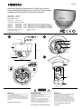
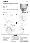
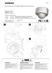
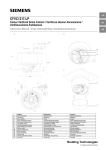
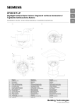
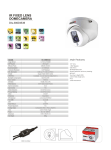
English
Instruction Manual for Colour Fixed Dome Camera
Instructiehandleiding Fixed focus kleuren domecamera
Installationsanleitung Fixfokus-Dome-Farbkamera
Model number
Modelnummer
Typen-Nummer
CFFC1310-LP
CFFC1315-LP
Part Code
Art. code
Art.-Nr
2GF1184-8AC
2GF1184-8AA
Accessories / Accessoires / Zubehör
CFFA-TD
2GF1086-8AA
Tinted Lower Dome / NL: Getinte dome / De: Getönte Kuppel
CFFA-IC29
2GF1086-8AB
2.9 mm — Replacement Lens / NL: Vervangingslens / D: Ersatzlinse
CFFA-IC37
2GF1086-8AK
3.7 mm — Replacement Lens / NL: Vervangingslens / D: Ersatzlinse
CFFA-IC60
2GF1086-8AF
6.0 mm — Replacement Lens / NL: Vervangingslens / D: Ersatzlinse
CFFA-IC12
2GF1086-8AE
12.0 mm — Replacement Lens / NL: Vervangingslens / D: Ersatzlinse
Document / Document / Dokument
Edition / Editie / Ausgabe
Supersedes / Vervangt / Ersetzt
A24205-A336-R555
Rev A.1
-
A
10
1
B
9
12
11
13
2
97,5 mm
3
C
4
112 mm
5
2
6
7
3
4
8
Warning
Waarschuwing
Warnung
To avoid electrical shock, do not open the cabinet. Refer
servicing to qualified personnel only.
The CAUTION label shown above is attached to the dome.
CAUTION: To reduce the risk of electric shock, do not
remove cover (or back). No user-serviceable parts inside.
Servicing should only be carried out by qualified service
personnel.
Open de behuizing niet, want dan loopt u het risico op een
elektrische schok. Laat alle reparaties door
gekwalificeerde technici uitvoeren.
De bovenstaande waarschuwingssticker is op de dome
bevestigd.
LET OP: Om het risico op elektrische schokken te
verkleinen, dient u de kap (of achterzijde) niet te
verwijderen. In het apparaat bevinden zich geen
onderdelen die u zelf kunt repareren. Laat elke vorm van
onderhoud over aan gekwalificeerde technici.
Zur Vermeidung von Elektroschocks darf das Gehäuse
nicht geöffnet werden. Servicearbeiten dürfen nur von
qualifiziertem Personal ausgeführt werden.
Der Warnhinweis oben ist an der Kuppel angebracht.
VORSICHT: Um die Gefahr eines Elektroschocks zu
verringern, darf das Gehäuse (oder die Rückseite) nicht
entfernt werden. Im Inneren befinden sich keine benutzerseitig zu wartenden Teile. Servicearbeiten dürfen nur von
qualifiziertem Kundendienstersonal ausgeführt werden.
Intended for indoor use only!
Alleen geschikt voor binnentoepassingen!
Nur für den Einsatz im Innenbereich
vorgesehen!
English
Dome camera
1 BNC connection cable
1 service monitor cable
2 fixing screws
2 wall plugs
Fixing template
Installation and operating instructions (this
document)
Optional settings
•
•
Dome camera parts
See figures A and B.
1. Cable entry holes
2. Unit casing
3. Inner liner
4. Dome casing
5. Mode setting DIP switches
6. V phase adjustment screw
7. Monitor output
8. Unit mounting holes
9. BNC connector
10.Power connector
11. Locking ring
12.Panning adjustment wheel
13.Axial ring
Installing the camera
Step 1: Connecting the cables
1. Connect the BNC cable to the BNC connector
(9).
2. Connect the power supply cable to the power
connector (10).
Use a 24 V AC or 12 V DC power supply.
Caution
If using a DC supply, make sure the polarity is
correct. Incorrect connection may cause
malfunction and/or damage to the video
camera.
Caution
Do not turn the DC/AES Mode switch to on
otherwise the electronic shutter speed will be
permanently set to 1/60(EIA) or 1/50(CCIR).
•
See figure C.
Note
Use a soft lint-free cloth to wipe the dome cover
clean and remove fingerprints.
1.
2.
3.
4.
Operation and storage
•
•
1. Place the template on the mounting surface
and mark the holes.
2. Drill two holes as marked.
3. Insert the wall plugs into the holes.
4. Fasten the unit with the screws provided.
Step 3: Adjusting the camera position
3. Turn the axial ring (13) in the desired direction.
Note
If the camera does not rotate smoothly, loosen
the locking ring completely. The locking ring has
an internal stop and will not come off.
Caution
Do not turn the lens more than 360° as this may
cause internal cables to disconnect or break.
4. Using the axial ring, carefully adjust the image
to the desired angle of view.
5. Lightly tighten the locking ring (11) and panning
adjustment wheel (12)
6. Hold the lens and fully retighten the locking ring
(11) and panning adjustment wheel (12).
Clean the joint surfaces of the unit.
Place the inner liner on the unit.
Place the dome on the unit.
Turn the dome clockwise and lock the cover in
place.
General guidelines
Step 2: Mounting the camera
Caution
Do not loosen the locking ring without holding
the lens in place; otherwise, the lens may rotate
with the locking ring and the cable may twist.
Line Lock (LL).
Set camera synchronisation to internal
(OFF) or line lock (ON). Line lock is only
available with a 24 V AC supply.
Step 4: Attaching the dome to the unit
3. Guide the cables through the cable entry holes
(1).
1. Hold the lens so that it does not rotate.
2. Loosen the locking ring (11) and panning
adjustment wheel (12).
Adjust the phase difference between cameras
(use V Phase adjustment screw (6).
Set the DIP switches (5) to activate or
deactivate the following features:
• Backlight compensation (BLC)
• Automatic gain control (AGC).
Automatically adjusts the picture to suit
ambient brightness
• Automatic electronic shutter (DC/AES).
Automatically adjusts the picture to suit the
brightness of the subject.
Avoid facing the camera directly toward very
bright objects (such as light fittings) for an
extended period.
Do not operate or store the unit in the following
locations:
• Extremely hot or cold places.
• Close to sources of strong magnetism.
• Close to sources of powerful
electromagnetic radiation, such as radios or
TV transmitters.
• In humid or excessively dusty places.
• Where exposed to mechanical vibration.
• Close to fluorescent lamps or objects that
reflect light.
• Under unstable or flickering light sources.
Cleaning
•
•
Use a soft, dry cloth to remove fingerprints or
dust from the dome.
If the dome is very dirty, use a small amount of
mild detergent on a damp cloth for cleaning.
Ensure the dome is dry before attaching the
dome to the unit.
Caution
Do not use volatile solvents such as alcohol,
benzene or thinners. These solvents may
damage the surface.
Transportation
Use the original packing material or materials of
equal quality.
CCD characteristics
The following conditions may be observed when
using a CCD camera. These are inherent to the
design and do not stem from any fault within the
camera itself.
• Vertical smear: This phenomenon occurs when
viewing a very bright object.
• Patterned noise: This is a fixed pattern which
may appear over the entire monitor screen
when the camera is operated at a high
temperature.
• Jagged picture: When viewing stripes, straight
lines, or similar patterns, the image on the
screen may appear jagged.
Specifications
General
Power requirement......12 V DC or 24 V AC
(Min. 5 W)
Power consumption ....3,5 W (max.)
Operating temperature-10 to +50°C, 90% RH max.
Storage temperature ...-20 to +60°C, 70% RH max.
External dimensions....112 x 97.5 mm
Weight.........................Approx. 0.29 kg
Unit material................ABS (30%) and
polycarbonate (70%)
Dome material.............Polycarbonate
Imaging system
Imaging device............Interline transfer 1/3 inch
CCD
Effective picture elements
CFFC1310-LP (Std. Res.)
PAL: 500(H) * 582(V)
CFFC1315-LP (High Res.)
PAL: 752(H) * 582(V)
TV system ...................PAL: 2:1 Interlace,
15.750 kHz horizontal,
50 Hz vertical
Optical system and other specifications
Focal length ................f=3.7 mm
Maximum relative aperture
F2.0
Synchronisation system
Internal or Line lock (24 V
AC only)
Horizontal resolution ...480 TV lines — High
Resolution model
330 TV lines — Std
Resolution model
Minimum illumination ..0.56 lx — High Resolution
model
0.31 lx — Std Resolution
model
(AGC ON, more than 50%
of image output r = 0.45,
without dome cover)
Video output................1.0 Vp-p 75 Ohm
Video S/N ratio............More than 50 dB (AGC
OFF, Weighted)
White balance .............Automatic (2500°K 10000°K)
AGC ............................ON/OFF switchable
BLC .............................ON (Center measured) /
OFF switchable
Information
This equipment has been tested and found to
comply with the limits for a Class A digital device,
pursuant to Part 15 of the FCC Rules. These limits
are designed to provide reasonable protection
against harmful interference when the equipment
is operated in a commercial environment.
This equipment generates, uses, and can radiate
radio frequency energy and, if not installed and
used in accordance with the instruction manual,
may cause harmful interference to radio
communications. Operation of this equipment in a
residential area may cause harmful interference in
which case the user will be required to correct the
interference at his own expense.
© 2003 Siemens Building Technologies: Fire and Security Products
•
•
•
•
•
•
•
Data and design subject to change without notice.
Package contents
English
Instruction Manual for Monochrome Fixed Dome Camera
Instructiehandleiding Monochroom fixed focus domecamera
Installationsanleitung SW Fixfokus-Dome-Kamera
Model number
Modelnummer
Typen-Nummer
CFFB1310-LC
CFFB1315-LC
Part Code
Art. code
Art.-Nr
2GF1084-8AC
2GF1084-8AA
Accessories / Accessoires / Zubehör
CFFA-TD
2GF1086-8AA
Tinted Lower Dome / NL: Getinte dome / De: Getönte Kuppel
CFFA-IC29
2GF1086-8AB
2.9 mm — Replacement Lens / NL: Vervangingslens / D: Ersatzlinse
CFFA-IC37
2GF1086-8AK
3.7 mm — Replacement Lens / NL: Vervangingslens / D: Ersatzlinse
CFFA-IC60
2GF1086-8AF
6.0 mm — Replacement Lens / NL: Vervangingslens / D: Ersatzlinse
CFFA-IC12
2GF1086-8AE
12.0 mm — Replacement Lens / NL: Vervangingslens / D: Ersatzlinse
Document / Document / Dokument
Edition / Editie / Ausgabe
Supersedes / Vervangt / Ersetzt
A24205-A336-R558
Rev A.1
-
A
10
1
B
9
12
11
13
2
97,5 mm
3
C
4
112 mm
5
2
6
7
3
4
8
Warning
Waarschuwing
Warnung
To avoid electrical shock, do not open the cabinet. Refer
servicing to qualified personnel only.
The CAUTION label shown above is attached to the dome.
CAUTION: To reduce the risk of electric shock, do not
remove cover (or back). No user-serviceable parts inside.
Servicing should only be carried out by qualified service
personnel.
Open de behuizing niet, want dan loopt u het risico op een
elektrische schok. Laat alle reparaties door
gekwalificeerde technici uitvoeren.
De bovenstaande waarschuwingssticker is op de dome
bevestigd.
LET OP: Om het risico op elektrische schokken te
verkleinen, dient u de kap (of achterzijde) niet te
verwijderen. In het apparaat bevinden zich geen
onderdelen die u zelf kunt repareren. Laat elke vorm van
onderhoud over aan gekwalificeerde technici.
Zur Vermeidung von Elektroschocks darf das Gehäuse
nicht geöffnet werden. Servicearbeiten dürfen nur von
qualifiziertem Personal ausgeführt werden.
Der Warnhinweis oben ist an der Kuppel angebracht.
VORSICHT: Um die Gefahr eines Elektroschocks zu
verringern, darf das Gehäuse (oder die Rückseite) nicht
entfernt werden. Im Inneren befinden sich keine benutzerseitig zu wartenden Teile. Servicearbeiten dürfen nur von
qualifiziertem Kundendienstersonal ausgeführt werden.
Intended for indoor use only!
Alleen geschikt voor binnentoepassingen!
Nur für den Einsatz im Innenbereich
vorgesehen!
English
Dome camera
1 BNC connection cable
1 service monitor cable
2 fixing screws
2 wall plugs
Fixing template
Installation and operating instructions (this
document)
Optional settings
•
•
Dome camera parts
See figures A and B.
1. Cable entry holes
2. Unit casing
3. Inner liner
4. Dome casing
5. Mode setting DIP switches
6. V phase adjustment screw
7. Monitor output
8. Unit mounting holes
9. BNC connector
10.Power connector
11. Locking ring
12.Panning adjustment wheel
13.Axial ring
Installing the camera
Step 1: Connecting the cables
1. Connect the BNC cable to the BNC connector
(9).
2. Connect the power supply cable to the power
connector (10).
Use a 24 V AC or 12 V DC power supply.
Caution
If using a DC supply, make sure the polarity is
correct. Incorrect connection may cause
malfunction and/or damage to the video
camera.
Caution
Do not turn the DC/AES Mode switch to on
otherwise the electronic shutter speed will be
permanently set to 1/60(EIA) or 1/50(CCIR).
•
See figure C.
Note
Use a soft lint-free cloth to wipe the dome cover
clean and remove fingerprints.
1.
2.
3.
4.
Operation and storage
•
•
1. Place the template on the mounting surface
and mark the holes.
2. Drill two holes as marked.
3. Insert the wall plugs into the holes.
4. Fasten the unit with the screws provided.
Step 3: Adjusting the camera position
3. Turn the axial ring (13) in the desired direction.
Note
If the camera does not rotate smoothly, loosen
the locking ring completely. The locking ring has
an internal stop and will not come off.
Caution
Do not turn the lens more than 360° as this may
cause internal cables to disconnect or break.
4. Using the axial ring, carefully adjust the image
to the desired angle of view.
5. Lightly tighten the locking ring (11) and panning
adjustment wheel (12)
6. Hold the lens and fully retighten the locking ring
(11) and panning adjustment wheel (12).
Clean the joint surfaces of the unit.
Place the inner liner on the unit.
Place the dome on the unit.
Turn the dome clockwise and lock the cover in
place.
General guidelines
Step 2: Mounting the camera
Caution
Do not loosen the locking ring without holding
the lens in place; otherwise, the lens may rotate
with the locking ring and the cable may twist.
Line Lock (LL).
Set camera synchronisation to internal
(OFF) or line lock (ON). Line lock is only
available with a 24 V AC supply.
Step 4: Attaching the dome to the unit
3. Guide the cables through the cable entry holes
(1).
1. Hold the lens so that it does not rotate.
2. Loosen the locking ring (11) and panning
adjustment wheel (12).
Adjust the phase difference between cameras
(use V Phase adjustment screw (6).
Set the DIP switches (5) to activate or
deactivate the following features:
• Backlight compensation (BLC)
• Automatic gain control (AGC).
Automatically adjusts the picture to suit
ambient brightness
• Automatic electronic shutter (DC/AES).
Automatically adjusts the picture to suit the
brightness of the subject.
Avoid facing the camera directly toward very
bright objects (such as light fittings) for an
extended period.
Do not operate or store the unit in the following
locations:
• Extremely hot or cold places.
• Close to sources of strong magnetism.
• Close to sources of powerful
electromagnetic radiation, such as radios or
TV transmitters.
• In humid or excessively dusty places.
• Where exposed to mechanical vibration.
• Close to fluorescent lamps or objects that
reflect light.
• Under unstable or flickering light sources.
Cleaning
•
•
Use a soft, dry cloth to remove fingerprints or
dust from the dome.
If the dome is very dirty, use a small amount of
mild detergent on a damp cloth for cleaning.
Ensure the dome is dry before attaching the
dome to the unit.
Caution
Do not use volatile solvents such as alcohol,
benzene or thinners. These solvents may
damage the surface.
Transportation
Use the original packing material or materials of
equal quality.
CCD characteristics
The following conditions may be observed when
using a CCD camera. These are inherent to the
design and do not stem from any fault within the
camera itself.
• Vertical smear: This phenomenon occurs when
viewing a very bright object.
• Patterned noise: This is a fixed pattern which
may appear over the entire monitor screen
when the camera is operated at a high
temperature.
• Jagged picture: When viewing stripes, straight
lines, or similar patterns, the image on the
screen may appear jagged.
Specifications
General
Power requirement......12 V DC or 24 V AC
(Min. 5 W)
Power consumption ....3 W (max.)
Operating temperature-10 to +50°C, 90% RH max.
Storage temperature ...-20 to +60°C, 70% RH max.
External dimensions....112 x 97.5 mm
Weight.........................Approx. 0.29 kg
Unit material................ABS (30%) and
polycarbonate (70%)
Dome material.............Polycarbonate
Imaging system
Imaging device............Interline transfer 1/3 inch
CCD
Effective picture elements
CFFB1310-LC (Std. Res.)
CCIR: 500(H) * 582(V)
CFFB1315-LC (High Res.)
CCIR: 752(H) * 582(V)
TV system ...................CCIR: 2:1 Interlace,
15.625 kHz horizontal,
50 Hz vertical
Optical system and other specifications
Focal length ................f=3.7 mm
Maximum relative aperture
F2.0
Synchronisation system
Internal or Line lock (24 V
AC only)
Horizontal resolution ...580 TV lines — High
Resolution model
400 TV lines — Std
Resolution model
Minimum illumination ..0.2 lx — High Resolution
model
0.13 lx — Std Resolution
model
(AGC ON, more than 50%
of image output r = 0.45,
without dome cover)
Video output................1.0 Vp-p 75 Ohm
Video S/N ratio............More than 50 dB (AGC
OFF, Weighted)
AGC ............................ON/OFF switchable
BLC .............................ON (Center measured) /
OFF switchable
Information
This equipment has been tested and found to
comply with the limits for a Class A digital device,
pursuant to Part 15 of the FCC Rules. These limits
are designed to provide reasonable protection
against harmful interference when the equipment
is operated in a commercial environment.
This equipment generates, uses, and can radiate
radio frequency energy and, if not installed and
used in accordance with the instruction manual,
may cause harmful interference to radio
communications. Operation of this equipment in a
residential area may cause harmful interference in
which case the user will be required to correct the
interference at his own expense.
© 2003 Siemens Building Technologies: Fire and Security Products
•
•
•
•
•
•
•
Data and design subject to change without notice.
Package contents